2002 NISSAN TERRANO sensor
[x] Cancel search: sensorPage 1027 of 1767
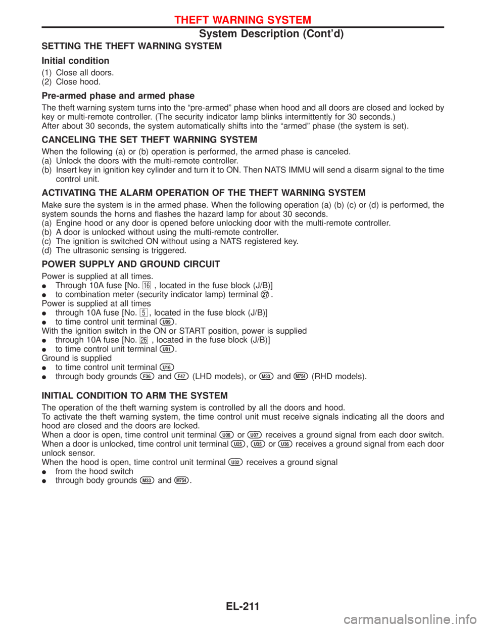
SETTING THE THEFT WARNING SYSTEM
Initial condition
(1) Close all doors.
(2) Close hood.
Pre-armed phase and armed phase
The theft warning system turns into the ªpre-armedº phase when hood and all doors are closed and locked by
key or multi-remote controller. (The security indicator lamp blinks intermittently for 30 seconds.)
After about 30 seconds, the system automatically shifts into the ªarmedº phase (the system is set).
CANCELING THE SET THEFT WARNING SYSTEM
When the following (a) or (b) operation is performed, the armed phase is canceled.
(a) Unlock the doors with the multi-remote controller.
(b) Insert key in ignition key cylinder and turn it to ON. Then NATS IMMU will send a disarm signal to the time
control unit.
ACTIVATING THE ALARM OPERATION OF THE THEFT WARNING SYSTEM
Make sure the system is in the armed phase. When the following operation (a) (b) (c) or (d) is performed, the
system sounds the horns and flashes the hazard lamp for about 30 seconds.
(a) Engine hood or any door is opened before unlocking door with the multi-remote controller.
(b) A door is unlocked without using the multi-remote controller.
(c) The ignition is switched ON without using a NATS registered key.
(d) The ultrasonic sensing is triggered.
POWER SUPPLY AND GROUND CIRCUIT
Power is supplied at all times.
IThrough 10A fuse [No.
16, located in the fuse block (J/B)]
Ito combination meter (security indicator lamp) terminalq
27.
Power is supplied at all times
Ithrough 10A fuse [No.
5, located in the fuse block (J/B)]
Ito time control unit terminal
U09.
With the ignition switch in the ON or START position, power is supplied
Ithrough 10A fuse [No.
26, located in the fuse block (J/B)]
Ito time control unit terminal
U01.
Ground is supplied
Ito time control unit terminal
U16
Ithrough body groundsF36andF47(LHD models), orM33andM754(RHD models).
INITIAL CONDITION TO ARM THE SYSTEM
The operation of the theft warning system is controlled by all the doors and hood.
To activate the theft warning system, the time control unit must receive signals indicating all the doors and
hood are closed and the doors are locked.
When a door is open, time control unit terminal
U06orU07receives a ground signal from each door switch.
When a door is unlocked, time control unit terminal
U25,U35orU36receives a ground signal from each door
unlock sensor.
When the hood is open, time control unit terminal
U32receives a ground signal
Ifrom the hood switch
Ithrough body grounds
M33andM754.
THEFT WARNING SYSTEM
System Description (Cont'd)
EL-211
Page 1028 of 1767
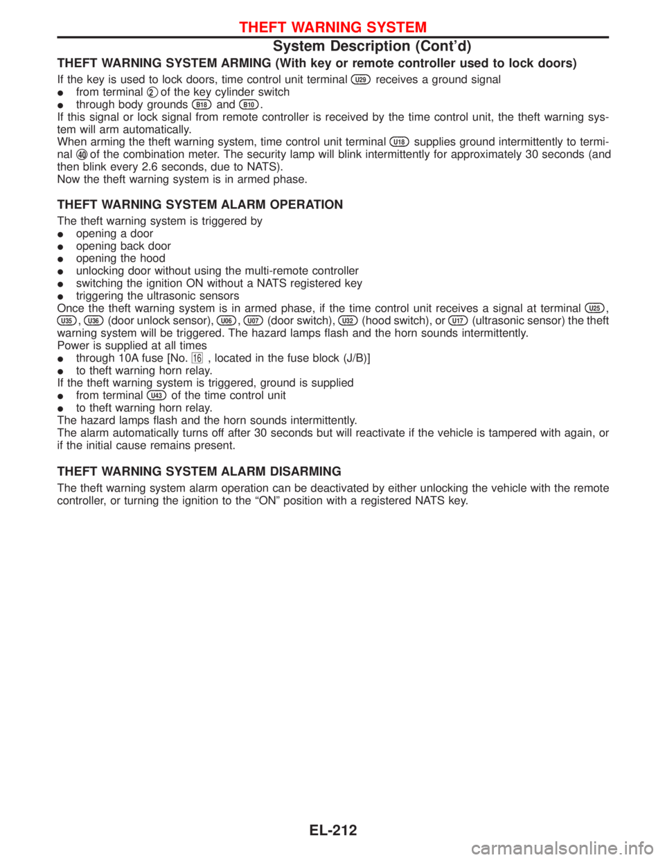
THEFT WARNING SYSTEM ARMING (With key or remote controller used to lock doors)
If the key is used to lock doors, time control unit terminalU29receives a ground signal
Ifrom terminalq
2of the key cylinder switch
Ithrough body grounds
B18andB10.
If this signal or lock signal from remote controller is received by the time control unit, the theft warning sys-
tem will arm automatically.
When arming the theft warning system, time control unit terminal
U18supplies ground intermittently to termi-
nalq
40of the combination meter. The security lamp will blink intermittently for approximately 30 seconds (and
then blink every 2.6 seconds, due to NATS).
Now the theft warning system is in armed phase.
THEFT WARNING SYSTEM ALARM OPERATION
The theft warning system is triggered by
Iopening a door
Iopening back door
Iopening the hood
Iunlocking door without using the multi-remote controller
Iswitching the ignition ON without a NATS registered key
Itriggering the ultrasonic sensors
Once the theft warning system is in armed phase, if the time control unit receives a signal at terminal
U25,
U35,U36(door unlock sensor),U06,U07(door switch),U32(hood switch), orU17(ultrasonic sensor) the theft
warning system will be triggered. The hazard lamps flash and the horn sounds intermittently.
Power is supplied at all times
Ithrough 10A fuse [No.
16, located in the fuse block (J/B)]
Ito theft warning horn relay.
If the theft warning system is triggered, ground is supplied
Ifrom terminal
U43of the time control unit
Ito theft warning horn relay.
The hazard lamps flash and the horn sounds intermittently.
The alarm automatically turns off after 30 seconds but will reactivate if the vehicle is tampered with again, or
if the initial cause remains present.
THEFT WARNING SYSTEM ALARM DISARMING
The theft warning system alarm operation can be deactivated by either unlocking the vehicle with the remote
controller, or turning the ignition to the ªONº position with a registered NATS key.
THEFT WARNING SYSTEM
System Description (Cont'd)
EL-212
Page 1046 of 1767
Trouble Diagnoses
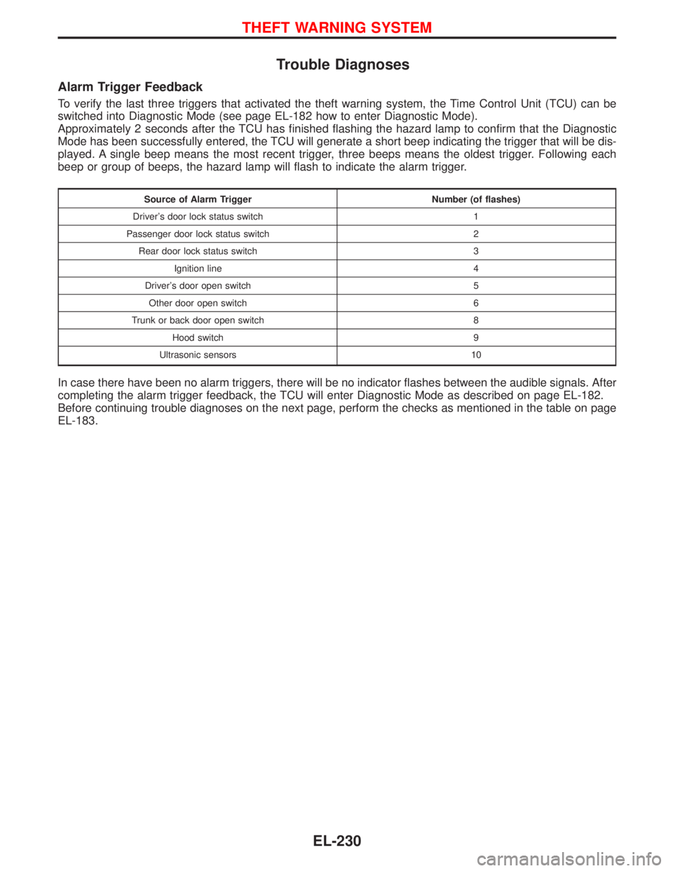
Alarm Trigger Feedback
To verify the last three triggers that activated the theft warning system, the Time Control Unit (TCU) can be
switched into Diagnostic Mode (see page EL-182 how to enter Diagnostic Mode).
Approximately 2 seconds after the TCU has finished flashing the hazard lamp to confirm that the Diagnostic
Mode has been successfully entered, the TCU will generate a short beep indicating the trigger that will be dis-
played. A single beep means the most recent trigger, three beeps means the oldest trigger. Following each
beep or group of beeps, the hazard lamp will flash to indicate the alarm trigger.
Source of Alarm Trigger Number (of flashes)
Driver's door lock status switch 1
Passenger door lock status switch 2
Rear door lock status switch 3
Ignition line 4
Driver's door open switch 5
Other door open switch 6
Trunk or back door open switch 8
Hood switch 9
Ultrasonic sensors 10
In case there have been no alarm triggers, there will be no indicator flashes between the audible signals. After
completing the alarm trigger feedback, the TCU will enter Diagnostic Mode as described on page EL-182.
Before continuing trouble diagnoses on the next page, perform the checks as mentioned in the table on page
EL-183.
THEFT WARNING SYSTEM
EL-230
Page 1047 of 1767
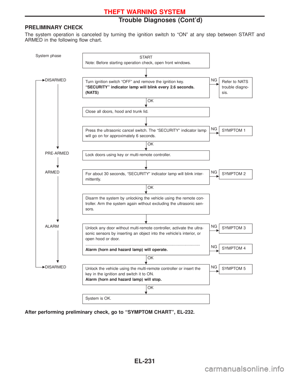
PRELIMINARY CHECK
The system operation is canceled by turning the ignition switch to ªONº at any step between START and
ARMED in the following flow chart.
System phase
START
Note: Before starting operation check, open front windows.
EDISARMED
Turn ignition switch ªOFFº and remove the ignition key.
ªSECURITYº indicator lamp will blink every 2.6 seconds.
(NATS)
OK
ENG
Refer to NATS
trouble diagno-
sis.
Close all doors, hood and trunk lid.
Press the ultrasonic cancel switch. The ªSECURITYº indicator lamp
will go on for approximately 6 seconds.
OK
ENG
SYMPTOM 1
PRE-ARMED
Lock doors using key or multi-remote controller.
ARMED
For about 30 seconds, ªSECURITYº indicator lamp will blink inter-
mittently.
OK
ENG
SYMPTOM 2
Disarm the system by unlocking the vehicle using the remote con-
troller. Arm the system again without excluding the ultrasonic sen-
sors.
ALARM
Unlock any door without multi-remote controller, activate the ultra-
sonic sensors by inserting an object into the vehicle's interior, or
open hood or door.
.......................................................................................................
Alarm (horn and hazard lamp) will operate.
OK
ENG
SYMPTOM 3
ENG
SYMPTOM 4
EDISARMED
Unlock the vehicle using the multi-remote controller or insert the
key in the ignition and switch it to ON.
Alarm (horn and hazard lamp) will stop.
OK
ENG
SYMPTOM 5
System is OK.
After performing preliminary check, go to ªSYMPTOM CHARTº, EL-232.
H
H
H
HH
HH
H
HH
HH
H
THEFT WARNING SYSTEM
Trouble Diagnoses (Cont'd)
EL-231
Page 1048 of 1767
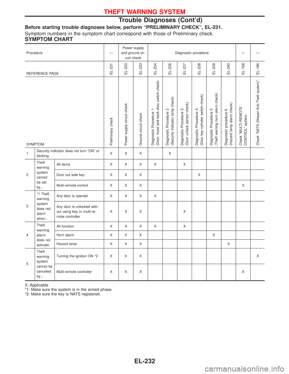
Before starting trouble diagnoses below, perform ªPRELIMINARY CHECKº, EL-231.
Symptom numbers in the symptom chart correspond with those of Preliminary check.
SYMPTOM CHART
Procedure ÐPower supply
and ground cir-
cuit checkDiagnostic procedure Ð Ð
REFERENCE PAGE
EL-231
EL-233
EL-233
EL-234
EL-236
EL-237
EL-238
EL-239
EL-240
EL-168
EL-186
SYMPTOMPreliminary check
Power supply circuit check
Ground circuit check
Diagnostic Procedure 1
(Door, hood and back door switch check)
Diagnostic Procedure 2
(Security indicator lamp check)
Diagnostic Procedure 3
(Door unlock sensor check)
Diagnostic Procedure 4
(Door key cylinder switch check)
Diagnostic Procedure 5
(Theft warning horn alarm check)
Diagnostic procedure 6
(Hazard lamp alarm check)
Check ªMULTI-REMOTE
CONTROLº system.
Check ªNATS (Nissan Anti-Theft system)º.
1Security indicator does not turn ªONº or
blinking.XXX X
2Theft
warning
system
cannot
be set
by...All itemsXXXX X
Door out side key X X X X
Multi-remote control X X X X
3*1 Theft
warning
system
does not
alarm
when...Any door is opened.XXXX
Any door is unlocked with-
out using key or multi-re-
mote controllerXXX X
4Theft
warning
alarm
does not
activate.All functionXXXX X
Horn alarm X X X X
Hazard lamp X X X X
5Theft
warning
system
cannot be
canceled
by...Turning the ignition ON *2 X X XX
Multi-remote controller X X X X
X: Applicable
*1: Make sure the system is in the armed phase.
*2: Make sure the key is NATS registered.
THEFT WARNING SYSTEM
Trouble Diagnoses (Cont'd)
EL-232
Page 1053 of 1767
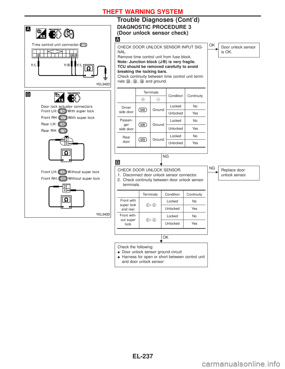
DIAGNOSTIC PROCEDURE 3
(Door unlock sensor check)
CHECK DOOR UNLOCK SENSOR INPUT SIG-
NAL.
Remove time control unit from fuse block.
Note: Junction block (J/B) is very fragile.
TCU should be removed carefully to avoid
breaking the locking bars.
Check continuity between time control unit termi-
nalsq
25,q35,q36and ground.
NG
EOK
Door unlock sensor
is OK.
CHECK DOOR UNLOCK SENSOR.
1. Disconnect door unlock sensor connector.
2. Check continuity between door unlock sensor
terminals.
OK
ENG
Replace door
unlock sensor.
Check the following:
IDoor unlock sensor ground circuit
IHarness for open or short between control unit
and door unlock sensor
Terminals
Condition Continuity
!@
Driver
side door
U35GroundLocked No
Unlocked Yes
Passen-
ger
side door
U36GroundLocked No
Unlocked Yes
Rear
door
U25GroundLocked No
Unlocked Yes
Terminals Condition Continuity
Front with
super lock
and rearq
2-q5Locked No
Unlocked Yes
Front with-
out super
lockq
2-q4Locked No
Unlocked Yes
YEL342D
YEL343D
H
H
THEFT WARNING SYSTEM
Trouble Diagnoses (Cont'd)
EL-237
Page 1107 of 1767
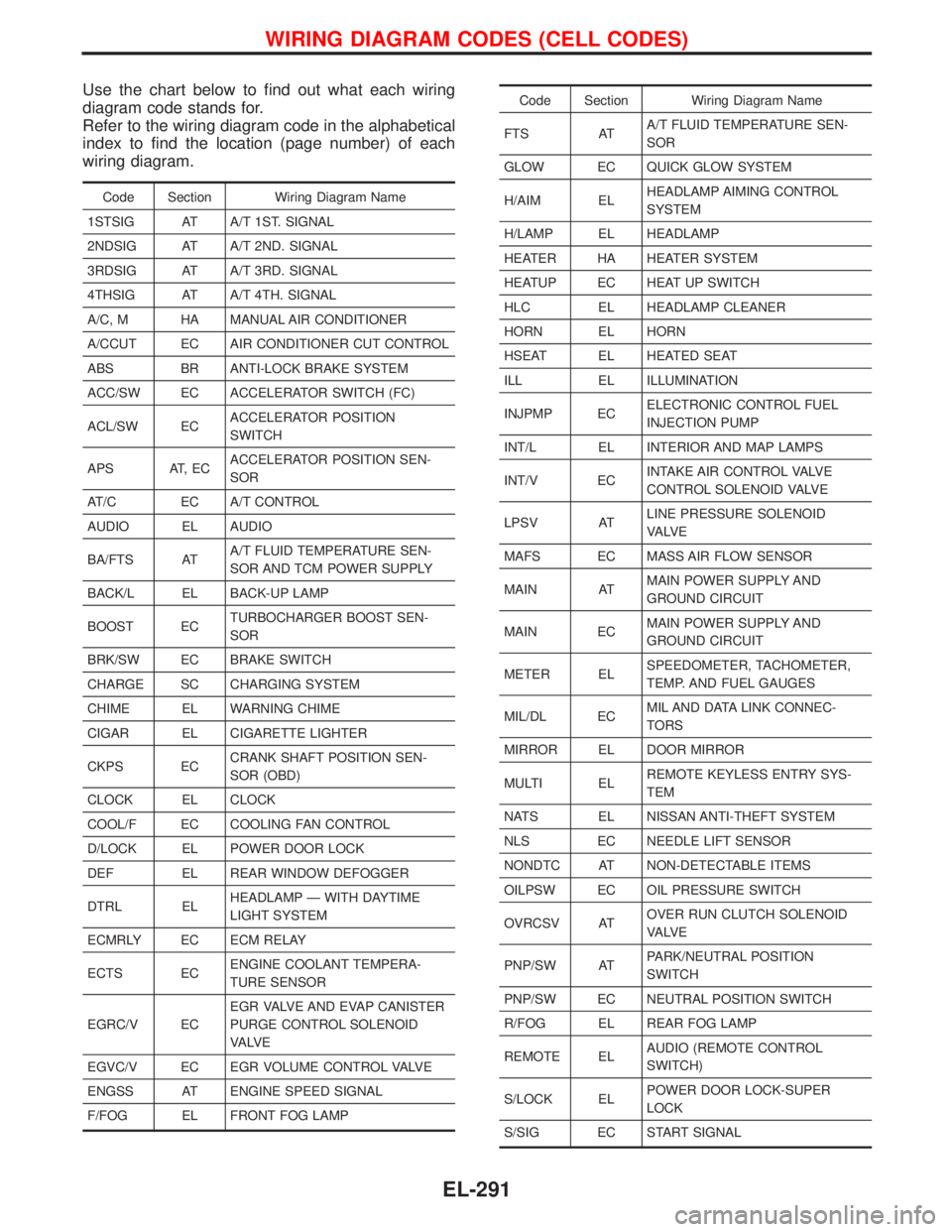
Use the chart below to find out what each wiring
diagram code stands for.
Refer to the wiring diagram code in the alphabetical
index to find the location (page number) of each
wiring diagram.
Code Section Wiring Diagram Name
1STSIG AT A/T 1ST. SIGNAL
2NDSIG AT A/T 2ND. SIGNAL
3RDSIG AT A/T 3RD. SIGNAL
4THSIG AT A/T 4TH. SIGNAL
A/C, M HA MANUAL AIR CONDITIONER
A/CCUT EC AIR CONDITIONER CUT CONTROL
ABS BR ANTI-LOCK BRAKE SYSTEM
ACC/SW EC ACCELERATOR SWITCH (FC)
ACL/SW ECACCELERATOR POSITION
SWITCH
APS AT, ECACCELERATOR POSITION SEN-
SOR
AT/C EC A/T CONTROL
AUDIO EL AUDIO
BA/FTS ATA/T FLUID TEMPERATURE SEN-
SOR AND TCM POWER SUPPLY
BACK/L EL BACK-UP LAMP
BOOST ECTURBOCHARGER BOOST SEN-
SOR
BRK/SW EC BRAKE SWITCH
CHARGE SC CHARGING SYSTEM
CHIME EL WARNING CHIME
CIGAR EL CIGARETTE LIGHTER
CKPS ECCRANK SHAFT POSITION SEN-
SOR (OBD)
CLOCK EL CLOCK
COOL/F EC COOLING FAN CONTROL
D/LOCK EL POWER DOOR LOCK
DEF EL REAR WINDOW DEFOGGER
DTRL ELHEADLAMP Ð WITH DAYTIME
LIGHT SYSTEM
ECMRLY EC ECM RELAY
ECTS ECENGINE COOLANT TEMPERA-
TURE SENSOR
EGRC/V ECEGR VALVE AND EVAP CANISTER
PURGE CONTROL SOLENOID
VA LV E
EGVC/V EC EGR VOLUME CONTROL VALVE
ENGSS AT ENGINE SPEED SIGNAL
F/FOG EL FRONT FOG LAMP
Code Section Wiring Diagram Name
FTS ATA/T FLUID TEMPERATURE SEN-
SOR
GLOW EC QUICK GLOW SYSTEM
H/AIM ELHEADLAMP AIMING CONTROL
SYSTEM
H/LAMP EL HEADLAMP
HEATER HA HEATER SYSTEM
HEATUP EC HEAT UP SWITCH
HLC EL HEADLAMP CLEANER
HORN EL HORN
HSEAT EL HEATED SEAT
ILL EL ILLUMINATION
INJPMP ECELECTRONIC CONTROL FUEL
INJECTION PUMP
INT/L EL INTERIOR AND MAP LAMPS
INT/V ECINTAKE AIR CONTROL VALVE
CONTROL SOLENOID VALVE
LPSV ATLINE PRESSURE SOLENOID
VA LV E
MAFS EC MASS AIR FLOW SENSOR
MAIN ATMAIN POWER SUPPLY AND
GROUND CIRCUIT
MAIN ECMAIN POWER SUPPLY AND
GROUND CIRCUIT
METER ELSPEEDOMETER, TACHOMETER,
TEMP. AND FUEL GAUGES
MIL/DL ECMIL AND DATA LINK CONNEC-
TORS
MIRROR EL DOOR MIRROR
MULTI ELREMOTE KEYLESS ENTRY SYS-
TEM
NATS EL NISSAN ANTI-THEFT SYSTEM
NLS EC NEEDLE LIFT SENSOR
NONDTC AT NON-DETECTABLE ITEMS
OILPSW EC OIL PRESSURE SWITCH
OVRCSV ATOVER RUN CLUTCH SOLENOID
VA LV E
PNP/SW ATPARK/NEUTRAL POSITION
SWITCH
PNP/SW EC NEUTRAL POSITION SWITCH
R/FOG EL REAR FOG LAMP
REMOTE ELAUDIO (REMOTE CONTROL
SWITCH)
S/LOCK ELPOWER DOOR LOCK-SUPER
LOCK
S/SIG EC START SIGNAL
WIRING DIAGRAM CODES (CELL CODES)
EL-291
Page 1108 of 1767
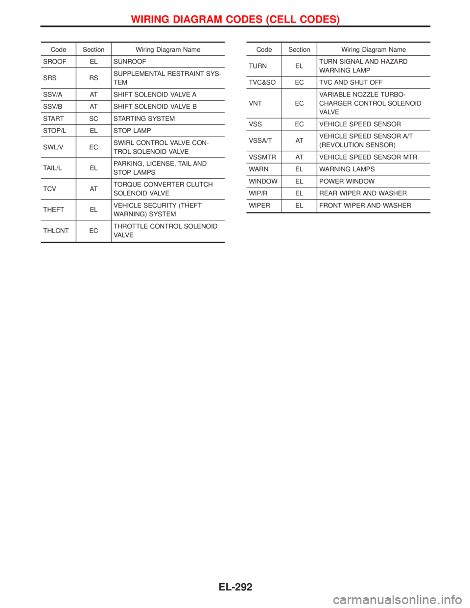
Code Section Wiring Diagram Name
SROOF EL SUNROOF
SRS RSSUPPLEMENTAL RESTRAINT SYS-
TEM
SSV/A AT SHIFT SOLENOID VALVE A
SSV/B AT SHIFT SOLENOID VALVE B
START SC STARTING SYSTEM
STOP/L EL STOP LAMP
SWL/V ECSWIRL CONTROL VALVE CON-
TROL SOLENOID VALVE
TAIL/L ELPARKING, LICENSE, TAIL AND
STOP LAMPS
TCV ATTORQUE CONVERTER CLUTCH
SOLENOID VALVE
THEFT ELVEHICLE SECURITY (THEFT
WARNING) SYSTEM
THLCNT ECTHROTTLE CONTROL SOLENOID
VA LV ECode Section Wiring Diagram Name
TURN ELTURN SIGNAL AND HAZARD
WARNING LAMP
TVC&SO EC TVC AND SHUT OFF
VNT ECVARIABLE NOZZLE TURBO-
CHARGER CONTROL SOLENOID
VA LV E
VSS EC VEHICLE SPEED SENSOR
VSSA/T ATVEHICLE SPEED SENSOR A/T
(REVOLUTION SENSOR)
VSSMTR AT VEHICLE SPEED SENSOR MTR
WARN EL WARNING LAMPS
WINDOW EL POWER WINDOW
WIP/R EL REAR WIPER AND WASHER
WIPER EL FRONT WIPER AND WASHER
WIRING DIAGRAM CODES (CELL CODES)
EL-292