2002 NISSAN TERRANO sensor
[x] Cancel search: sensorPage 1318 of 1767
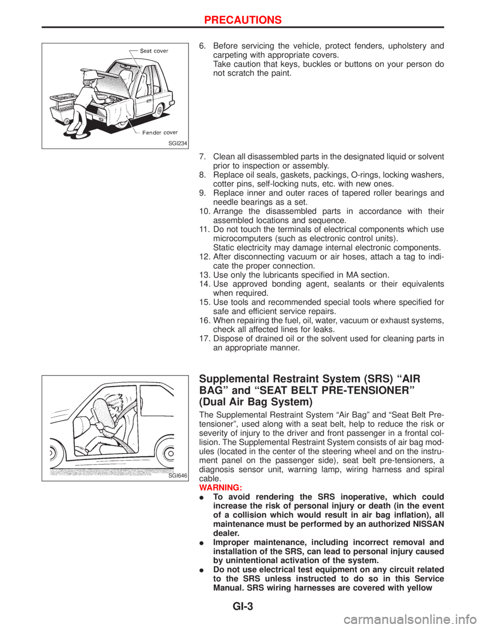
6. Before servicing the vehicle, protect fenders, upholstery and
carpeting with appropriate covers.
Take caution that keys, buckles or buttons on your person do
not scratch the paint.
7. Clean all disassembled parts in the designated liquid or solvent
prior to inspection or assembly.
8. Replace oil seals, gaskets, packings, O-rings, locking washers,
cotter pins, self-locking nuts, etc. with new ones.
9. Replace inner and outer races of tapered roller bearings and
needle bearings as a set.
10. Arrange the disassembled parts in accordance with their
assembled locations and sequence.
11. Do not touch the terminals of electrical components which use
microcomputers (such as electronic control units).
Static electricity may damage internal electronic components.
12. After disconnecting vacuum or air hoses, attach a tag to indi-
cate the proper connection.
13. Use only the lubricants specified in MA section.
14. Use approved bonding agent, sealants or their equivalents
when required.
15. Use tools and recommended special tools where specified for
safe and efficient service repairs.
16. When repairing the fuel, oil, water, vacuum or exhaust systems,
check all affected lines for leaks.
17. Dispose of drained oil or the solvent used for cleaning parts in
an appropriate manner.
Supplemental Restraint System (SRS) ªAIR
BAGº and ªSEAT BELT PRE-TENSIONERº
(Dual Air Bag System)
The Supplemental Restraint System ªAir Bagº and ªSeat Belt Pre-
tensionerº, used along with a seat belt, help to reduce the risk or
severity of injury to the driver and front passenger in a frontal col-
lision. The Supplemental Restraint System consists of air bag mod-
ules (located in the center of the steering wheel and on the instru-
ment panel on the passenger side), seat belt pre-tensioners, a
diagnosis sensor unit, warning lamp, wiring harness and spiral
cable.
WARNING:
ITo avoid rendering the SRS inoperative, which could
increase the risk of personal injury or death (in the event
of a collision which would result in air bag inflation), all
maintenance must be performed by an authorized NISSAN
dealer.
IImproper maintenance, including incorrect removal and
installation of the SRS, can lead to personal injury caused
by unintentional activation of the system.
IDo not use electrical test equipment on any circuit related
to the SRS unless instructed to do so in this Service
Manual. SRS wiring harnesses are covered with yellow
SGI234
SGI646
PRECAUTIONS
GI-3
Page 1338 of 1767
Incident Simulation Tests
INTRODUCTION
Sometimes the symptom is not present when the vehicle is brought in for service. If possible, re-create the
conditions present at the time of the incident. Doing so may help avoid a No Trouble Found Diagnosis. The
following section illustrates ways to simulate the conditions/environment under which the owner experiences
an electrical incident.
The section is broken into the six following topics:
IVehicle vibration
IHeat sensitive
IFreezing
IWater intrusion
IElectrical load
ICold or hot start up
Get a thorough description of the incident from the customer. It is important for simulating the conditions of
the problem.
VEHICLE VIBRATION
The problem may occur or become worse while driving on a rough road or when engine is vibrating (idle with
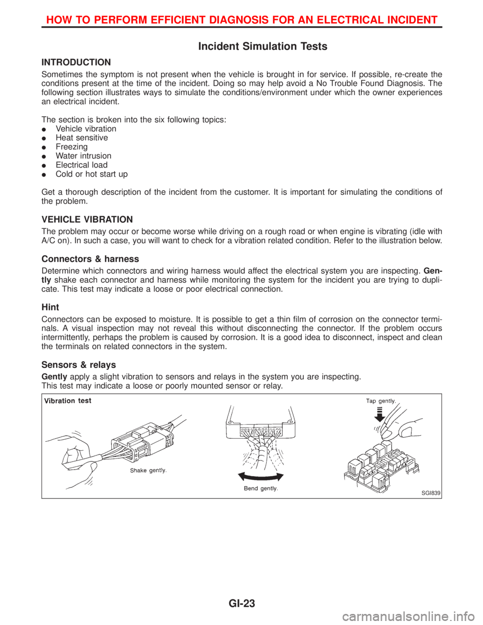
A/C on). In such a case, you will want to check for a vibration related condition. Refer to the illustration below.
Connectors & harness
Determine which connectors and wiring harness would affect the electrical system you are inspecting.Gen-
tlyshake each connector and harness while monitoring the system for the incident you are trying to dupli-
cate. This test may indicate a loose or poor electrical connection.
Hint
Connectors can be exposed to moisture. It is possible to get a thin film of corrosion on the connector termi-
nals. A visual inspection may not reveal this without disconnecting the connector. If the problem occurs
intermittently, perhaps the problem is caused by corrosion. It is a good idea to disconnect, inspect and clean
the terminals on related connectors in the system.
Sensors & relays
Gentlyapply a slight vibration to sensors and relays in the system you are inspecting.
This test may indicate a loose or poorly mounted sensor or relay.
SGI839
HOW TO PERFORM EFFICIENT DIAGNOSIS FOR AN ELECTRICAL INCIDENT
GI-23
Page 1350 of 1767
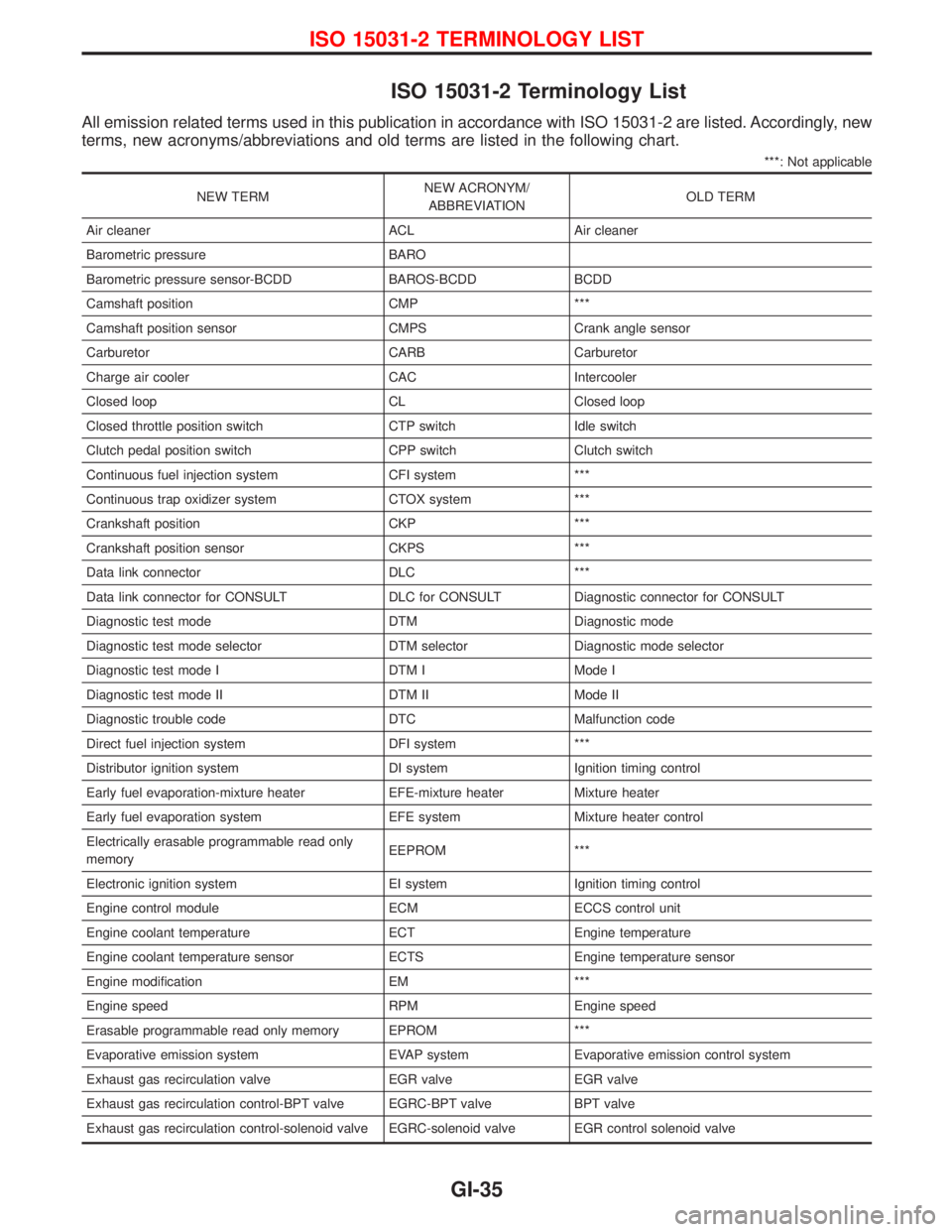
ISO 15031-2 Terminology List
All emission related terms used in this publication in accordance with ISO 15031-2 are listed. Accordingly, new
terms, new acronyms/abbreviations and old terms are listed in the following chart.
***: Not applicable
NEW TERMNEW ACRONYM/
ABBREVIATIONOLD TERM
Air cleaner ACL Air cleaner
Barometric pressure BARO
Barometric pressure sensor-BCDD BAROS-BCDD BCDD
Camshaft position CMP ***
Camshaft position sensor CMPS Crank angle sensor
Carburetor CARB Carburetor
Charge air cooler CAC Intercooler
Closed loop CL Closed loop
Closed throttle position switch CTP switch Idle switch
Clutch pedal position switch CPP switch Clutch switch
Continuous fuel injection system CFI system ***
Continuous trap oxidizer system CTOX system ***
Crankshaft position CKP ***
Crankshaft position sensor CKPS ***
Data link connector DLC ***
Data link connector for CONSULT DLC for CONSULT Diagnostic connector for CONSULT
Diagnostic test mode DTM Diagnostic mode
Diagnostic test mode selector DTM selector Diagnostic mode selector
Diagnostic test mode I DTM I Mode I
Diagnostic test mode II DTM II Mode II
Diagnostic trouble code DTC Malfunction code
Direct fuel injection system DFI system ***
Distributor ignition system DI system Ignition timing control
Early fuel evaporation-mixture heater EFE-mixture heater Mixture heater
Early fuel evaporation system EFE system Mixture heater control
Electrically erasable programmable read only
memoryEEPROM ***
Electronic ignition system EI system Ignition timing control
Engine control module ECM ECCS control unit
Engine coolant temperature ECT Engine temperature
Engine coolant temperature sensor ECTS Engine temperature sensor
Engine modification EM ***
Engine speed RPM Engine speed
Erasable programmable read only memory EPROM ***
Evaporative emission system EVAP system Evaporative emission control system
Exhaust gas recirculation valve EGR valve EGR valve
Exhaust gas recirculation control-BPT valve EGRC-BPT valve BPT valve
Exhaust gas recirculation control-solenoid valve EGRC-solenoid valve EGR control solenoid valve
ISO 15031-2 TERMINOLOGY LIST
GI-35
Page 1351 of 1767
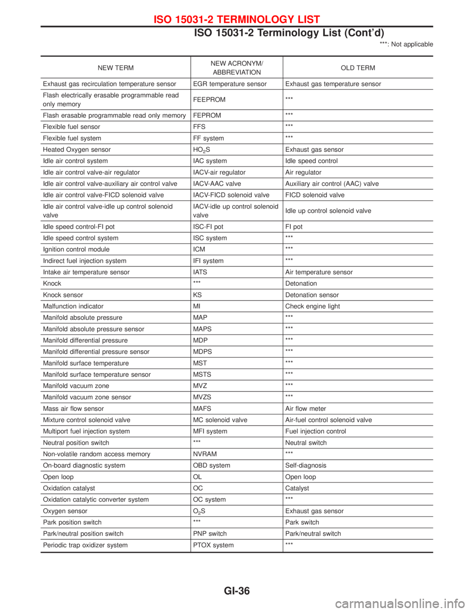
***: Not applicable
NEW TERMNEW ACRONYM/
ABBREVIATIONOLD TERM
Exhaust gas recirculation temperature sensor EGR temperature sensor Exhaust gas temperature sensor
Flash electrically erasable programmable read
only memoryFEEPROM ***
Flash erasable programmable read only memory FEPROM ***
Flexible fuel sensor FFS ***
Flexible fuel system FF system ***
Heated Oxygen sensor HO
2S Exhaust gas sensor
Idle air control system IAC system Idle speed control
Idle air control valve-air regulator IACV-air regulator Air regulator
Idle air control valve-auxiliary air control valve IACV-AAC valve Auxiliary air control (AAC) valve
Idle air control valve-FICD solenoid valve IACV-FICD solenoid valve FICD solenoid valve
Idle air control valve-idle up control solenoid
valveIACV-idle up control solenoid
valveIdle up control solenoid valve
Idle speed control-FI pot ISC-FI pot FI pot
Idle speed control system ISC system ***
Ignition control module ICM ***
Indirect fuel injection system IFI system ***
Intake air temperature sensor IATS Air temperature sensor
Knock *** Detonation
Knock sensor KS Detonation sensor
Malfunction indicator MI Check engine light
Manifold absolute pressure MAP ***
Manifold absolute pressure sensor MAPS ***
Manifold differential pressure MDP ***
Manifold differential pressure sensor MDPS ***
Manifold surface temperature MST ***
Manifold surface temperature sensor MSTS ***
Manifold vacuum zone MVZ ***
Manifold vacuum zone sensor MVZS ***
Mass air flow sensor MAFS Air flow meter
Mixture control solenoid valve MC solenoid valve Air-fuel control solenoid valve
Multiport fuel injection system MFI system Fuel injection control
Neutral position switch *** Neutral switch
Non-volatile random access memory NVRAM ***
On-board diagnostic system OBD system Self-diagnosis
Open loop OL Open loop
Oxidation catalyst OC Catalyst
Oxidation catalytic converter system OC system ***
Oxygen sensor O
2S Exhaust gas sensor
Park position switch *** Park switch
Park/neutral position switch PNP switch Park/neutral switch
Periodic trap oxidizer system PTOX system ***
ISO 15031-2 TERMINOLOGY LIST
ISO 15031-2 Terminology List (Cont'd)
GI-36
Page 1352 of 1767
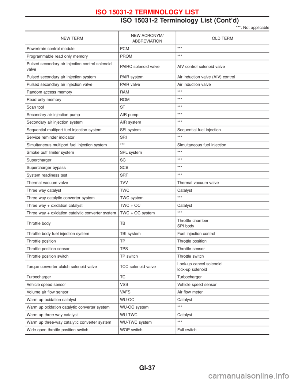
***: Not applicable
NEW TERMNEW ACRONYM/
ABBREVIATIONOLD TERM
Powertrain control module PCM ***
Programmable read only memory PROM ***
Pulsed secondary air injection control solenoid
valvePAIRC solenoid valve AIV control solenoid valve
Pulsed secondary air injection system PAIR system Air induction valve (AIV) control
Pulsed secondary air injection valve PAIR valve Air induction valve
Random access memory RAM ***
Read only memory ROM ***
Scan tool ST ***
Secondary air injection pump AIR pump ***
Secondary air injection system AIR system ***
Sequential multiport fuel injection system SFI system Sequential fuel injection
Service reminder indicator SRI ***
Simultaneous multiport fuel injection system *** Simultaneous fuel injection
Smoke puff limiter system SPL system ***
Supercharger SC ***
Supercharger bypass SCB ***
System readiness test SRT ***
Thermal vacuum valve TVV Thermal vacuum valve
Three way catalyst TWC Catalyst
Three way catalytic converter system TWC system ***
Three way + oxidation catalyst TWC + OC Catalyst
Three way + oxidation catalytic converter system TWC + OC system ***
Throttle body TBThrottle chamber
SPI body
Throttle body fuel injection system TBI system Fuel injection control
Throttle position TP Throttle position
Throttle position sensor TPS Throttle sensor
Throttle position switch TP switch Throttle switch
Torque converter clutch solenoid valve TCC solenoid valveLock-up cancel solenoid
lock-up solenoid
Turbocharger TC Turbocharger
Vehicle speed sensor VSS Vehicle speed sensor
Volume air flow sensor VAFS Air flow meter
Warm up oxidation catalyst WU-OC Catalyst
Warm up oxidation catalytic converter system WU-OC system ***
Warm up three-way catalyst WU-TWC Catalyst
Warm up three-way catalytic converter system WU-TWC system ***
Wide open throttle position switch WOP switch Full switch
ISO 15031-2 TERMINOLOGY LIST
ISO 15031-2 Terminology List (Cont'd)
GI-37
Page 1419 of 1767
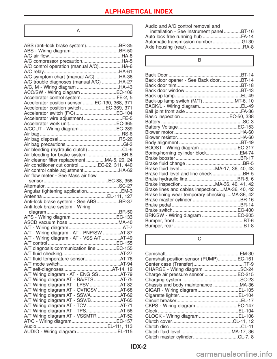
A
ABS (anti-lock brake system).........................BR-35
ABS - Wiring diagram ....................................BR-50
A/C air flow .......................................................HA-8
A/C compressor precaution..............................HA-5
A/C control operation (manual A/C) .................HA-6
A/C relay.........................................................HA-61
A/C symptom chart (manual A/C) ..................HA-36
A/C trouble diagnoses (manual A/C) .............HA-27
A/C, M - Wiring diagram ................................HA-43
ACC/SW - Wiring diagram ...........................EC-106
Accelerator control system ...........................FE-2, 5
Accelerator position sensor .........EC-130, 368, 371
Accelerator position switch ..................EC-369, 371
Accelerator switch (F/C) ...............................EC-104
Accelerator wire adjustment .............................FE-5
Accelerator work unit....................................EC-365
A/CCUT - Wiring diagram ............................EC-289
Air bag ..............................................................RS-6
Air bag disposal..............................................RS-20
Air bag precautions ...........................................GI-3
Air bleeding (hydraulic clutch) ..........................CL-6
Air bleeding for brake system ..........................BR-8
Air cleaner filter replacement ..............MA-5, 20, 24
Air conditioner cut control ..............EC-22, 311, 440
Air control cable adjustment...........................HA-62
Air flow meter - See Mass air flow
sensor .................................................EC-88, 356
Alternator ........................................................SC-27
Angular tightening application..........................EM-3
Antenna .................................................EL-111, 127
Anti-lock brake system - See ABS .................BR-37
Anti-lock brake system - Wiring
diagram .......................................................BR-50
APS - Wiring diagram ..................................EC-133
ASCD vacuum hose ......................................MA-40
A/T - Wiring diagram .........................................AT-7
A/T - Wiring diagram - AT - PNP/SW .............AT-87
A/T - Wiring diagram - AT - VSS A/T ..............AT-49
A/T control ....................................................EC-155
A/T diagnosis communication line ...............EC-155
A/T fluid checking ............................................AT-27
A/T fluid temperature sensor...........................AT-76
A/T mode switch..............................................AT-94
A/T self-diagnoses ....................................AT-14, 19
A/T Wiring diagram - AT - ENG SS ................AT-79
A/T Wiring diagram AT - BA/FTS ....................AT-75
A/T Wiring diagram AT - LPSV .......................AT-82
A/T Wiring diagram AT - OVRCSV .................AT-68
A/T Wiring diagram AT - SSV/A ......................AT-62
A/T Wiring diagram AT - SSV/B ......................AT-65
A/T Wiring diagram AT - TCV .........................AT-71
A/T Wiring diagram AT - TPS..........................AT-56
A/T Wiring diagram AT - VSSMTR .................AT-52
AT/C - Wiring diagram..................................EC-157
Audio......................................................EL-111, 113
AUDIO - Wiring diagram ...............................EL-115Audio and A/C control removal and
installation - See Instrument panel .............BT-16
Auto lock free running hub .............................FA-14
Automatic transmission number ......................GI-30
Axle housing (rear) ...........................................RA-8
B
Back Door .......................................................BT-14
Back door opener - See Back door ................BT-14
Back door trim.................................................BT-18
Back door window...........................................BT-43
Back-up lamp ..................................................EL-49
Back-up lamp switch (M/T) ........................MT-6, 10
BACK/L - Wiring diagram................................EL-49
Ball joint front axle ..........................................FA-36
Basic inspection .....................................EC-50, 338
Battery ..............................................................SC-3
Battery Voltage .............................................EC-153
Blower motor ..................................................HA-60
Blower resistor................................................HA-60
Body alignment ...............................................BT-49
BOOST - Wiring diagram .............................EC-217
Boring/horning cylinder block.........................EM-74
Brake booster .................................................BR-17
Brake fluid change ...........................................BR-5
Brake fluid level ...........................MA-17, 36, 40, 43
Brake fluid level and line check .......................BR-5
Brake hydraulic line......................................BR-5, 6
Brake inspection ..........................MA-36, 40, 41, 42
Brake lines and cables inspection.....MA-36, 40, 42
Brake lining wear temporary checking ....MA-36, 42
Brake master cylinder ....................................BR-16
Brake pedal ....................................................BR-14
Brake switch .................................................EC-400
BRK/SW - Wiring diagram ...........................EC-205
Bumper, front ....................................................BT-6
Bumper, rear .....................................................BT-8
C
Camshaft ........................................................EM-30
Camshaft position sensor (PUMP)...............EC-161
Center case (Transfer) ......................................TF-9
CHARGE - Wiring diagram ............................SC-24
Charge air pressure sensor .........................EC-215
Charging system ............................................SC-23
Chassis and body maintenance ....................MA-36
CIGAR - Wiring diagram ...............................EL-105
Cigarette lighter.............................................EL-104
Circuit breaker.................................................EL-17
CKPS - Wiring diagram ................................EC-147
Clock .............................................................EL-104
CLOCK - Wiring diagram ..............................EL-106
Clutch cover ..............................................CL-11, 12
Clutch disc ......................................................CL-11
Clutch fluid level ......................................MA-17, 36
Clutch master cylinder ..................................CL-7, 8
ALPHABETICAL INDEX
IDX-2
Page 1420 of 1767
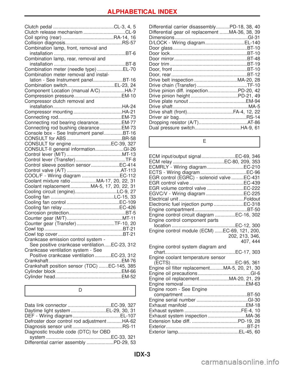
Clutch pedal .............................................CL-3, 4, 5
Clutch release mechanism ...............................CL-9
Coil spring (rear) ......................................RA-14, 16
Collision diagnosis..........................................RS-57
Combination lamp, front, removal and
installation .....................................................BT-6
Combination lamp, rear, removal and
installation .....................................................BT-8
Combination meter (needle type) ...................EL-70
Combination meter removal and instal-
lation - See Instrument panel......................BT-16
Combination switch...................................EL-23, 24
Component Location (manual A/C) ..................HA-7
Compression pressure ...................................EM-10
Compressor clutch removal and
installation ...................................................HA-24
Compressor mounting ....................................HA-21
Connecting rod...............................................EM-73
Connecting rod bearing clearance.................EM-77
Connecting rod bushing clearance ................EM-73
Console box - See Instrument panel ..............BT-16
CONSULT for ABS .........................................BR-58
CONSULT for engine .............................EC-39, 327
CONSULT-II general information.....................GI-26
Control lever (M/T) .........................................MT-13
Control lever (Transfer) .....................................TF-8
Control sleeve position sensor .....................EC-414
Control valve (A/T) ........................................AT-113
COOL/F - Wiring diagram ............................EC-112
Coolant mixture ratio ...................MA-17, 20, 22, 31
Coolant replacement ...............MA-5, 17, 20, 22, 31
Cooling circuit (engine)...............................LC-9, 27
Cooling fan ...............................................LC-15, 33
Cooling fan control .......................................EC-109
Cooling fan relay ..........................................EC-426
Corrosion protection..........................................BT-5
Counter gear (M/T) .........................................MT-11
Counter gear (Transfer) ............................TF-10, 20
Cowl top ..........................................................BT-21
Cowl top cover ................................................BT-21
Crankcase emission control system -
See positive crankcase ventilation .....EC-23, 312
Crankcase ventilation system - See
Positive crankcase ventilation ............EC-23, 312
Crankshaft ......................................................EM-76
Crankshaft position sensor (TDC) .......EC-145, 385
Cylinder block ................................................EM-66
Cylinder head .................................................EM-52
D
Data link connector ................................EC-39, 327
Daytime light system ..........................EL-29, 30, 31
DEF - Wiring diagram ...................................EL-107
Defroster door control rod adjustment ...........HA-62
Diagnosis sensor unit .....................................RS-11
Diagnostic trouble code (DTC) for OBD
system ................................................EC-33, 321
Differential carrier assembly ....................PD-29, 53Differential carrier disassembly..........PD-18, 38, 40
Differential gear oil replacement .......MA-36, 38, 39
Dimensions ......................................................GI-31
D/LOCK - Wiring diagram .............................EL-140
Door glass .......................................................BT-10
Door lock .........................................................BT-10
Door mirror ......................................................BT-48
Door trim .........................................................BT-19
Door, front .......................................................BT-10
Door, rear ........................................................BT-12
Drive belt inspection ................................MA-20, 28
Drive chain (Transfer) .....................................TF-10
Drive pinion diff. inspection ......................PD-20, 42
Drive pinion height ...................................PD-21, 49
Drive plate runout ..........................................EM-94
Drive shaft ........................................................MA-5
Drive shaft (front)..................................FA-4, 12, 22
Driver air bag..................................................RS-14
Dropping resistor (A/T)....................................AT-86
Dual pressure switch..................................HA-9, 61
E
ECM input/output signal .........................EC-69, 346
ECM relay ......................................EC-80, 209, 353
ECMRLY - Wiring diagram ...........................EC-210
ECTS - Wiring diagram ..................................EC-96
EGR control (EGRC) - solenoid valve .........EC-431
EGR control valve ........................................EC-439
EGR volume control valve ...........................EC-222
EGVC/V - Wiring diagram ............................EC-225
Electrical unit ................................................Foldout
Electronic fuel injection pump ......................EC-318
Engine compartment .......................................BT-50
Engine control circuit diagram ...............EC-16, 302
Engine control component parts
location ...............................................EC-12, 300
Engine control module (ECM) ......EC-69, 121, 200,
202, 213, 346,
407, 444
Engine control system diagram and
chart....................................................EC-17, 303
Engine coolant temperature sensor
(ECTS)................................................EC-95, 361
Engine oil filter replacement..........MA-5, 20, 21, 30
Engine oil precautions .......................................GI-6
Engine oil replacement ......................MA-20, 21, 29
Engine removal ..............................................EM-63
Engine room - See Engine
compartment ...............................................BT-50
Engine serial number ......................................GI-30
Exhaust manifold ...........................................EM-18
Exhaust system ..........................................FE-4, 10
Exhaust system inspection ............................MA-36
Extension tube diff. ..................................PD-19, 28
Exterior ............................................................BT-21
Exterior lamp.............................................EL-45, 60
ALPHABETICAL INDEX
IDX-3
Page 1421 of 1767
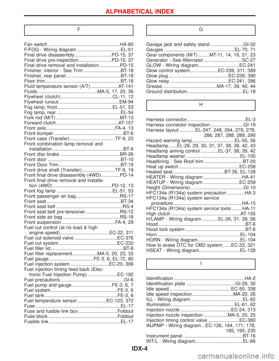
F
Fan switch ......................................................HA-60
F/FOG - Wiring diagram .................................EL-51
Final drive disassembly............................PD-15, 37
Final drive pre-inspection .........................PD-15, 37
Final drive removal and installation ...............PD-15
Finisher, interior - See Trim ............................BT-18
Finisher, rear panel .........................................BT-18
Floor trim .........................................................BT-18
Fluid temperature sensor (A/T) .....................AT-141
Fluids .............................................MA-5, 17, 20, 36
Flywheel (clutch) .......................................CL-11, 12
Flywheel runout..............................................EM-94
Fog lamp, front .........................................EL-51, 53
Fog lamp, rear ................................................EL-54
Fork rod (M/T) ................................................MT-13
Forward clutch...............................................AT-157
Front axle ....................................................FA-4, 13
Front bumper ....................................................BT-6
Front case (Transfer) ..................................TF-9, 23
Front combination lamp removal and
installation .....................................................BT-6
Front disc brake .............................................BR-26
Front door .......................................................BT-10
Front Door Trim...............................................BT-19
Front drive shaft (Transfer) .........................TF-9, 19
Front final drive disassembly (4WD) ..............PD-14
Front final drive removal and installa-
tion (4WD) ............................................PD-12, 13
Front fog lamp ..........................................EL-51, 53
Front passenger air bag .................................RS-17
Front seat ........................................................BT-34
Front seat belt ..................................................RS-4
Front seat belt pre-tensioner ..........................RS-12
Front side air bag ...........................................RS-18
Front suspension ........................................FA-4, 29
Fuel cut control (at no load & high
engine speed) .....................................EC-22, 311
Fuel cut solenoid valve ................................EC-376
Fuel cut system ............................................EC-232
Fuel filler lid.......................................................BT-8
Fuel filter replacement...................MA-5, 20, 23, 33
Fuel gauge..................................FE-3, 6, EL-72, 80
Fuel injection system .............................EC-20, 306
Fuel injection timing feed back (Elec-
tronic Fuel Injection Pump) ......................EC-192
Fuel precautions ................................................GI-6
Fuel pump and gauge ..............................FE-3, 6, 7
Fuel system ..................................................FE-3, 6
Fuel tank .......................................................FE-3, 6
Fuel temperature sensor ......................EC-123, 372
Fuse ................................................................EL-17
Fuse and fusible link box .............................Foldout
Fuse block ....................................................Foldout
Fusible link ......................................................EL-17GGarage jack and safety stand .........................GI-32
Gauges .....................................................EL-70, 71
Gear components (M/T) ........MT-11, 14, 16, 21, 23
Generator - See Alternator .............................SC-27
GLOW - Wiring diagram...............................EC-241
Glow control system.....................EC-239, 311, 389
Glow plug .............................................EC-239, 390
Glow relay ............................................EC-241, 396
Grease .........................................MA-17, 39, 40, 44
Ground distribution..........................................EL-18
H
Harness connector ............................................EL-3
Harness connector inspection .........................GI-19
Harness layout ............EL-247, 248, 264, 276, 278,
286, 287, 288, 289, 290
Hazard warning lamp................................EL-55, 56
Headlamp ......EL-26, 29, 30, 31, 37, 38, 39, 42, 43
Headlamp aiming control .............EL-37, 38, 39, 42
Headlamp washer .........................................EL-100
Headlining - See Roof trim .............................BT-20
Heat up switch..............................................EC-258
Heated seat .......................................BT-36, EL-128
HEATER - Wiring diagram .............................HA-41
HEATUP - Wiring diagram ...........................EC-259
Height (Dimensions) ........................................GI-10
HFC134a (R134a) system precaution .............HA-3
HFC134a (R134a) system service
procedure....................................................HA-15
HFC134a (R134a) system service tools ........HA-11
High clutch ....................................................AT-155
H/LAMP - Wiring diagram ............EL-26, 31, 39, 56
Hood..................................................................BT-6
Hood lock system .............................................BT-6
Horn ..............................................................EL-104
HORN - Wiring diagram................................EL-104
How to erase DTC for OBD system ......EC-33, 321
HSEAT - Wiring diagram...............................EL-128
I
Identification .....................................................HA-2
Identification plate .....................................GI-29, 30
Idle speed...............................................EC-50, 338
Idle speed inspection ...............................MA-20, 26
ILL - Wiring diagram .......................................EL-62
Illumination ................................................EL-61, 62
Injection nozzle ......................................EC-24, 313
Injection nozzle inspection ..................MA-5, 20, 25
Injection timing control valve ........................EC-380
INJPMP - Wiring diagram ...EC-126, 164, 171, 178,
185, 195, 235
Instrument panel .............................................BT-16
INT/L - Wiring diagram....................................EL-66
ALPHABETICAL INDEX
IDX-4