2002 NISSAN TERRANO power steering
[x] Cancel search: power steeringPage 1462 of 1767
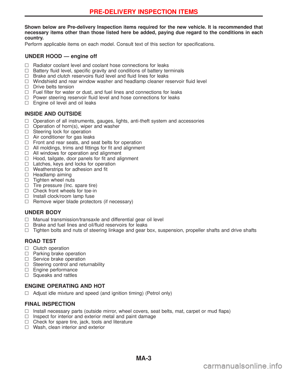
Shown below are Pre-delivery Inspection items required for the new vehicle. It is recommended that
necessary items other than those listed here be added, paying due regard to the conditions in each
country.
Perform applicable items on each model. Consult text of this section for specifications.
UNDER HOOD Ð engine off
lRadiator coolant level and coolant hose connections for leaks
lBattery fluid level, specific gravity and conditions of battery terminals
lBrake and clutch reservoirs fluid level and fluid lines for leaks
lWindshield and rear window washer and headlamp cleaner reservoir fluid level
lDrive belts tension
lFuel filter for water or dust, and fuel lines and connections for leaks
lPower steering reservoir fluid level and hose connections for leaks
lEngine oil level and oil leaks
INSIDE AND OUTSIDE
lOperation of all instruments, gauges, lights, anti-theft system and accessories
lOperation of horn(s), wiper and washer
lSteering lock for operation
lAir conditioner for gas leaks
lFront and rear seats, and seat belts for operation
lAll moldings, trims and fittings for fit and alignment
lAll windows for operation and alignment
lHood, tailgate, door panels for fit and alignment
lLatches, keys and locks for operation
lWeatherstrips for adhesion and fit
lHeadlamp aiming
lTighten wheel nuts
lTire pressure (Inc. spare tire)
lCheck front wheels for toe-in
lInstall clock/room lamp fuse
lRemove wiper blade protectors (if necessary)
UNDER BODY
lManual transmission/transaxle and differential gear oil level
lBrake and fuel lines and oil/fluid reservoirs for leaks
lTighten bolts and nuts of steering linkage and gear box, suspension, propeller shafts and drive shafts
ROAD TEST
lClutch operation
lParking brake operation
lService brake operation
lSteering control and returnability
lEngine performance
lSqueaks and rattles
ENGINE OPERATING AND HOT
lAdjust idle mixture and speed (and ignition timing) (Petrol only)
FINAL INSPECTION
lInstall necessary parts (outside mirror, wheel covers, seat belts, mat, carpet or mud flaps)
lInspect for interior and exterior metal and paint damage
lCheck for spare tire, jack, tools and literature
lWash, clean interior and exterior
PRE-DELIVERY INSPECTION ITEMS
MA-3
Page 1466 of 1767
![NISSAN TERRANO 2002 Service Repair Manual Chassis and Body Maintenance
Abbreviations: R = Replace I = Inspect. Correct or replace if necessary L = Lubricate T = Tighten
[ ] = At the specified mileage only
MAINTENANCE OPERATION MAINTENANCE INT](/manual-img/5/57393/w960_57393-1465.png "NISSAN TERRANO 2002 Service Repair Manual Chassis and Body Maintenance
Abbreviations: R = Replace I = Inspect. Correct or replace if necessary L = Lubricate T = Tighten
[ ] = At the specified mileage only
MAINTENANCE OPERATION MAINTENANCE INT")
Chassis and Body Maintenance
Abbreviations: R = Replace I = Inspect. Correct or replace if necessary L = Lubricate T = Tighten
[ ] = At the specified mileage only
MAINTENANCE OPERATION MAINTENANCE INTERVAL
Refer-
ence
page Perform on a kilometer basis, but on
a semi-annual basis when driving
less than 20,000 km (12,000 miles)
per year.km x 1,000 10 20 30 40 50 60 70 80 90 100 110 120
(miles x 1,000) (6) (12) (18) (24) (30) (36) (42) (48) (54) (60) (66) (72)
Months 6 12 18 24 30 36 42 48 54 50 66 72
Underhood and under vehicle
Headlamp aimingIIIIIIEL-37
Wheel alignment (if necessary, rotate & balance wheels)IIIIIIMA-43
Brake pads, discs & other components*IIIIIIMA-40
Brake linings, drums & other components*IIIIIIMA-41
Foot brake, parking brake & clutch (for free play, stroke &
operation)IIIIIIMA-42
Brake booster vacuum hoses, connections, check valve I I I MA-40
Brake & clutch, systems and fluid (for level and leaks)IIIIIIMA-36/
MA-40
Brake fluid*R R R MA-43
Power steering fluid and lines (for level and leaks)IIIIIIMA-44
Air bag system See NOTE (1)RS-15
Ventilation air filter*RRRRMA-44
Transfer and standard differential gear oil* I I R I I RMA-37/
MA-38
Manual transmission oil I I I [R] I I MA-36
LSD gear oil (for level and leaks)* I I R I I R MA-38
Steering gear & linkage, axle & suspension parts, propeller
shaft and exhaust system*IIIIIIMA-43/
FA-4/
RA-4/
MA-38/
MA-36
Greasing points of steering gear linkage,
propeller shaft and suspension*See NOTE (2)LLLLLLMA-44/
MA-38
Drive shafts*IIIIIIFA-13
Front wheel bearing grease*IRIRIRMA-39
Free running hub grease*IIIIIIMA-40
Body mounting bolts and nutsTTTTTTBT-48
Body corrosion See NOTE (3)MA-47
NOTE: (1) Inspect after 10 years, then every 2 years.
(2) The propeller shaft should be re-greased daily if it is immersed in water.
(3) Inspect once per year.
* Maintenance items with ª*º should be performed more frequently according to ªMaintenance under severe driving
conditionsº.
PERIODIC MAINTENANCE
Maintenance Schedule for Diesel Engine
Models (annual mileage < 30,000 km/year)
(Cont'd)
MA-7
Page 1469 of 1767
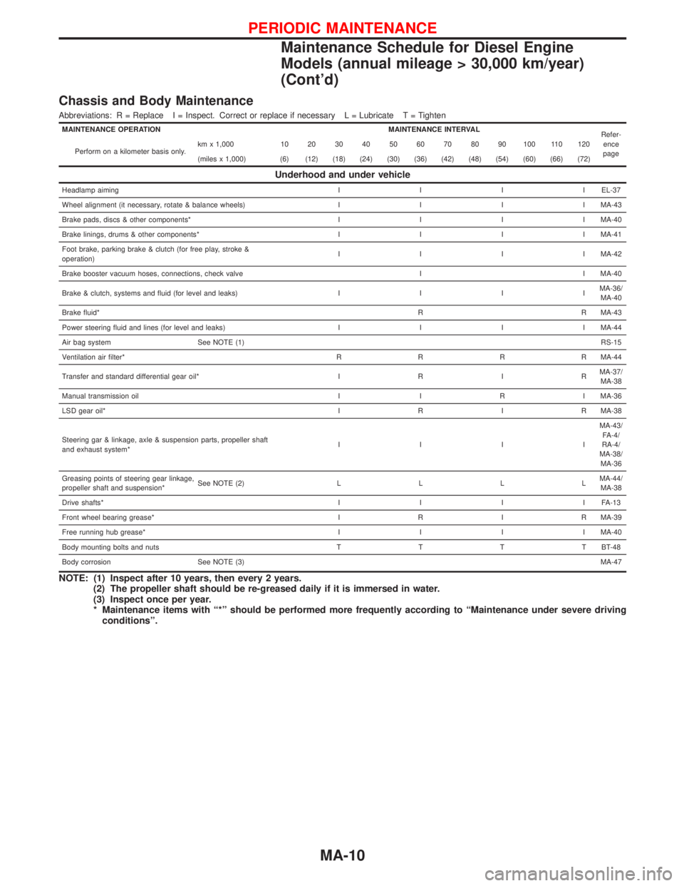
Chassis and Body Maintenance
Abbreviations: R = Replace I = Inspect. Correct or replace if necessary L = Lubricate T = Tighten
MAINTENANCE OPERATION MAINTENANCE INTERVAL
Refer-
ence
page Perform on a kilometer basis only.km x 1,000 10 20 30 40 50 60 70 80 90 100 110 120
(miles x 1,000) (6) (12) (18) (24) (30) (36) (42) (48) (54) (60) (66) (72)
Underhood and under vehicle
Headlamp aimingIIIIEL-37
Wheel alignment (it necessary, rotate & balance wheels)IIIIMA-43
Brake pads, discs & other components*IIIIMA-40
Brake linings, drums & other components*IIIIMA-41
Foot brake, parking brake & clutch (for free play, stroke &
operation)IIIIMA-42
Brake booster vacuum hoses, connections, check valve I I MA-40
Brake & clutch, systems and fluid (for level and leaks)IIIIMA-36/
MA-40
Brake fluid*R R MA-43
Power steering fluid and lines (for level and leaks)IIIIMA-44
Air bag system See NOTE (1)RS-15
Ventilation air filter*RRRRMA-44
Transfer and standard differential gear oil*IRIRMA-37/
MA-38
Manual transmission oil I I R I MA-36
LSD gear oil*IRIRMA-38
Steering gar & linkage, axle & suspension parts, propeller shaft
and exhaust system*IIIIMA-43/
FA-4/
RA-4/
MA-38/
MA-36
Greasing points of steering gear linkage,
propeller shaft and suspension*See NOTE (2)LLLLMA-44/
MA-38
Drive shafts*IIIIFA-13
Front wheel bearing grease*IRIRMA-39
Free running hub grease*IIIIMA-40
Body mounting bolts and nutsTTTTBT-48
Body corrosion See NOTE (3)MA-47
NOTE: (1) Inspect after 10 years, then every 2 years.
(2) The propeller shaft should be re-greased daily if it is immersed in water.
(3) Inspect once per year.
* Maintenance items with ª*º should be performed more frequently according to ªMaintenance under severe driving
conditionsº.
PERIODIC MAINTENANCE
Maintenance Schedule for Diesel Engine
Models (annual mileage > 30,000 km/year)
(Cont'd)
MA-10
Page 1476 of 1767
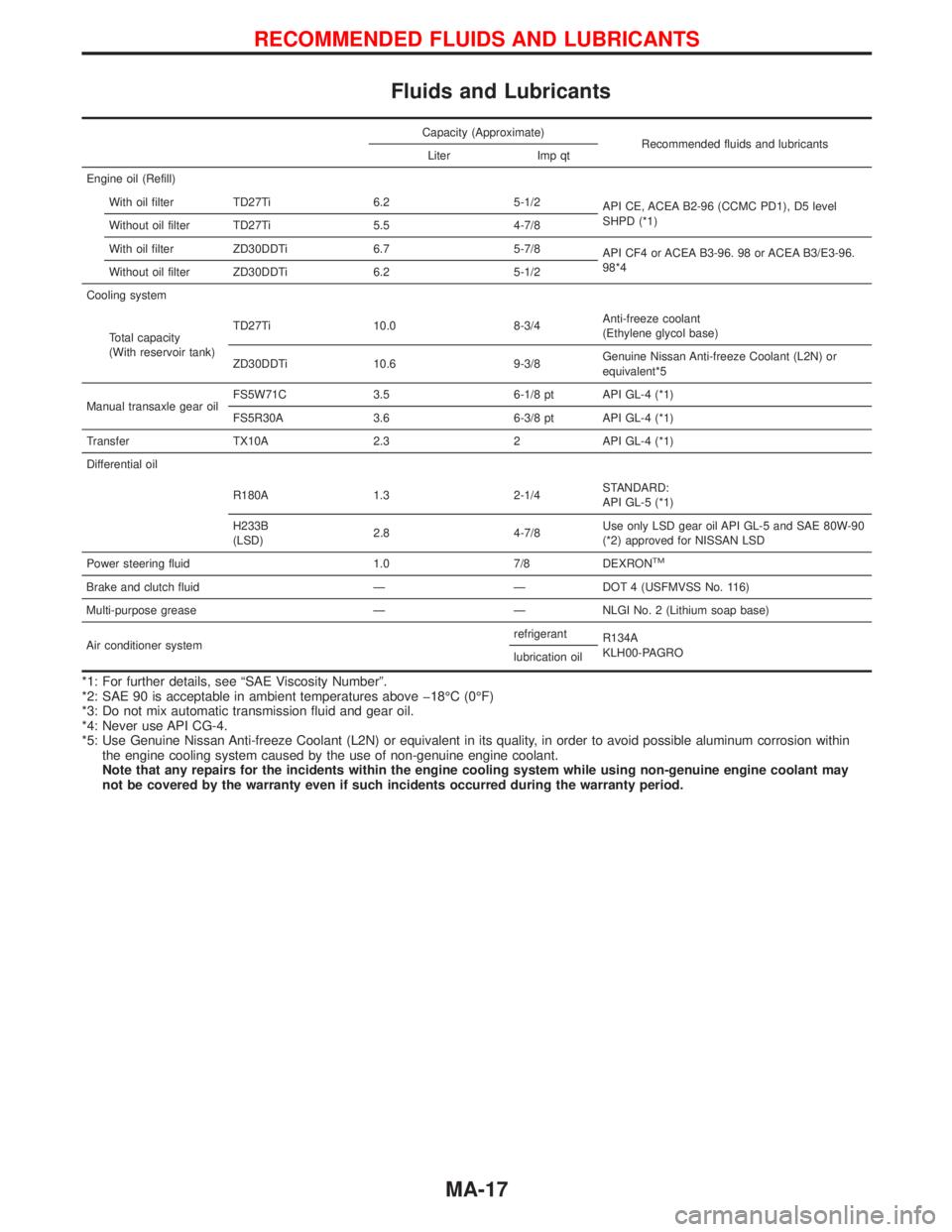
Fluids and Lubricants
Capacity (Approximate)
Recommended fluids and lubricants
Liter Imp qt
Engine oil (Refill)
With oil filter TD27Ti 6.2 5-1/2
API CE, ACEA B2-96 (CCMC PD1), D5 level
SHPD (*1)
Without oil filter TD27Ti 5.5 4-7/8
With oil filter ZD30DDTi 6.7 5-7/8
API CF4 or ACEA B3-96. 98 or ACEA B3/E3-96.
98*4
Without oil filter ZD30DDTi 6.2 5-1/2
Cooling system
Total capacity
(With reservoir tank)TD27Ti 10.0 8-3/4Anti-freeze coolant
(Ethylene glycol base)
ZD30DDTi 10.6 9-3/8Genuine Nissan Anti-freeze Coolant (L2N) or
equivalent*5
Manual transaxle gear oilFS5W71C 3.5 6-1/8 pt API GL-4 (*1)
FS5R30A 3.6 6-3/8 pt API GL-4 (*1)
Transfer TX10A 2.3 2 API GL-4 (*1)
Differential oil
R180A 1.3 2-1/4STANDARD:
API GL-5 (*1)
H233B
(LSD)2.8 4-7/8Use only LSD gear oil API GL-5 and SAE 80W-90
(*2) approved for NISSAN LSD
Power steering fluid 1.0 7/8 DEXRON
TM
Brake and clutch fluid Ð Ð DOT 4 (USFMVSS No. 116)
Multi-purpose grease Ð Ð NLGI No. 2 (Lithium soap base)
Air conditioner systemrefrigerant
R134A
KLH00-PAGRO
lubrication oil
*1: For further details, see ªSAE Viscosity Numberº.
*2: SAE 90 is acceptable in ambient temperatures above þ18ÉC (0ÉF)
*3: Do not mix automatic transmission fluid and gear oil.
*4: Never use API CG-4.
*5: Use Genuine Nissan Anti-freeze Coolant (L2N) or equivalent in its quality, in order to avoid possible aluminum corrosion within
the engine cooling system caused by the use of non-genuine engine coolant.
Note that any repairs for the incidents within the engine cooling system while using non-genuine engine coolant may
not be covered by the warranty even if such incidents occurred during the warranty period.
RECOMMENDED FLUIDS AND LUBRICANTS
MA-17
Page 1479 of 1767
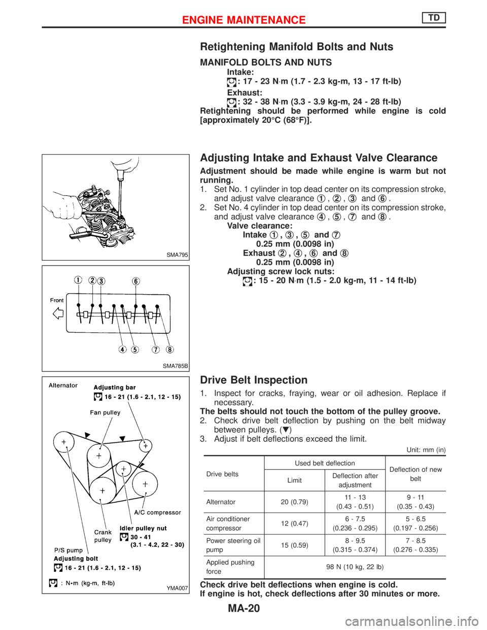
Retightening Manifold Bolts and Nuts
MANIFOLD BOLTS AND NUTS
Intake:
:17-23N×m (1.7 - 2.3 kg-m, 13 - 17 ft-lb)
Exhaust:
:32-38N×m (3.3 - 3.9 kg-m, 24 - 28 ft-lb)
Retightening should be performed while engine is cold
[approximately 20ÉC (68ÉF)].
Adjusting Intake and Exhaust Valve Clearance
Adjustment should be made while engine is warm but not
running.
1. Set No. 1 cylinder in top dead center on its compression stroke,
and adjust valve clearanceq
1,q2,q3andq6.
2. Set No. 4 cylinder in top dead center on its compression stroke,
and adjust valve clearanceq
4,q5,q7andq8.
Valve clearance:
Intakeq
1,q3,q5andq7
0.25 mm (0.0098 in)
Exhaustq
2,q4,q6andq8
0.25 mm (0.0098 in)
Adjusting screw lock nuts:
:15-20N×m (1.5 - 2.0 kg-m, 11 - 14 ft-lb)
Drive Belt Inspection
1. Inspect for cracks, fraying, wear or oil adhesion. Replace if
necessary.
The belts should not touch the bottom of the pulley groove.
2. Check drive belt deflection by pushing on the belt midway
between pulleys. (H)
3. Adjust if belt deflections exceed the limit.
Unit: mm (in)
Drive beltsUsed belt deflection
Deflection of new
belt
LimitDeflection after
adjustment
Alternator 20 (0.79)11-13
(0.43 - 0.51)9-11
(0.35 - 0.43)
Air conditioner
compressor12 (0.47)6 - 7.5
(0.236 - 0.295)5 - 6.5
(0.197 - 0.256)
Power steering oil
pump15 (0.59)8 - 9.5
(0.315 - 0.374)7 - 8.5
(0.276 - 0.335)
Applied pushing
force98 N (10 kg, 22 lb)
Check drive belt deflections when engine is cold.
If engine is hot, check deflections after 30 minutes or more.
SMA795
SMA785B
YMA007
ENGINE MAINTENANCETD
MA-20
Page 1503 of 1767
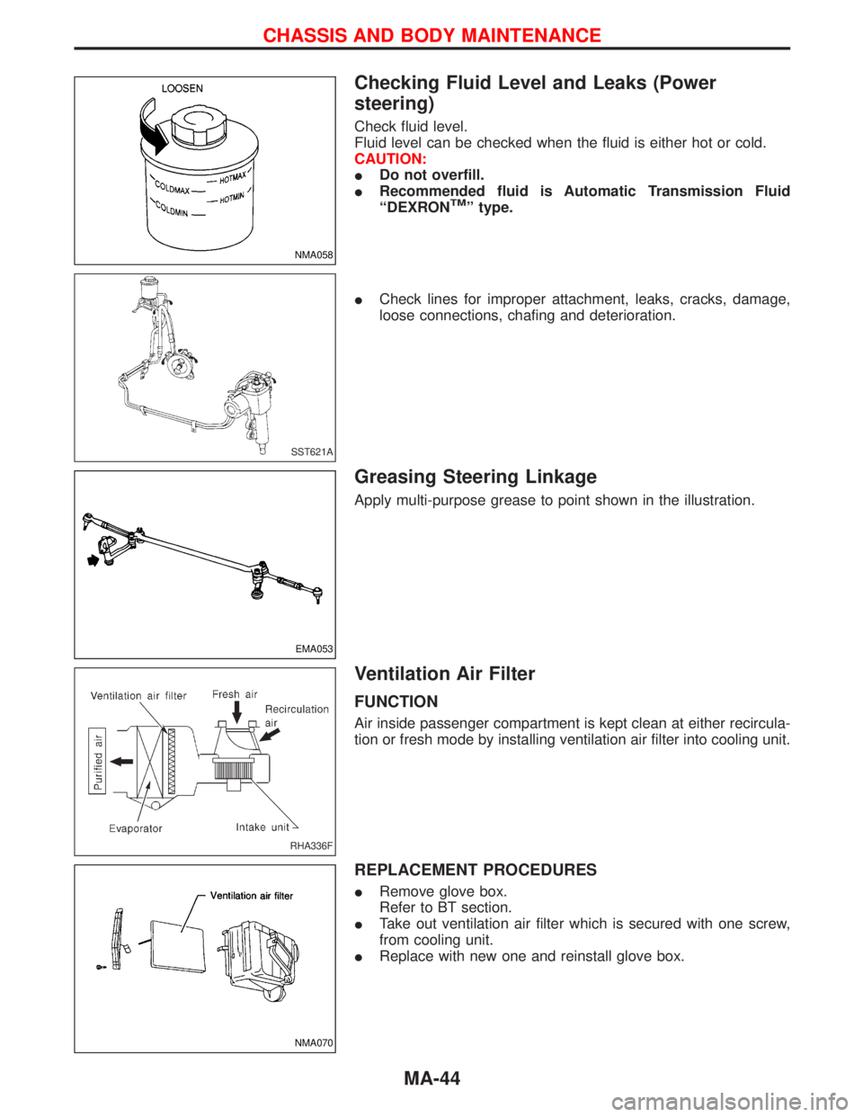
Checking Fluid Level and Leaks (Power
steering)
Check fluid level.
Fluid level can be checked when the fluid is either hot or cold.
CAUTION:
IDo not overfill.
IRecommended fluid is Automatic Transmission Fluid
ªDEXRON
TMº type.
ICheck lines for improper attachment, leaks, cracks, damage,
loose connections, chafing and deterioration.
Greasing Steering Linkage
Apply multi-purpose grease to point shown in the illustration.
Ventilation Air Filter
FUNCTION
Air inside passenger compartment is kept clean at either recircula-
tion or fresh mode by installing ventilation air filter into cooling unit.
REPLACEMENT PROCEDURES
IRemove glove box.
Refer to BT section.
ITake out ventilation air filter which is secured with one screw,
from cooling unit.
IReplace with new one and reinstall glove box.
NMA058
SST621A
EMA053
RHA336F
NMA070
CHASSIS AND BODY MAINTENANCE
MA-44
Page 1507 of 1767
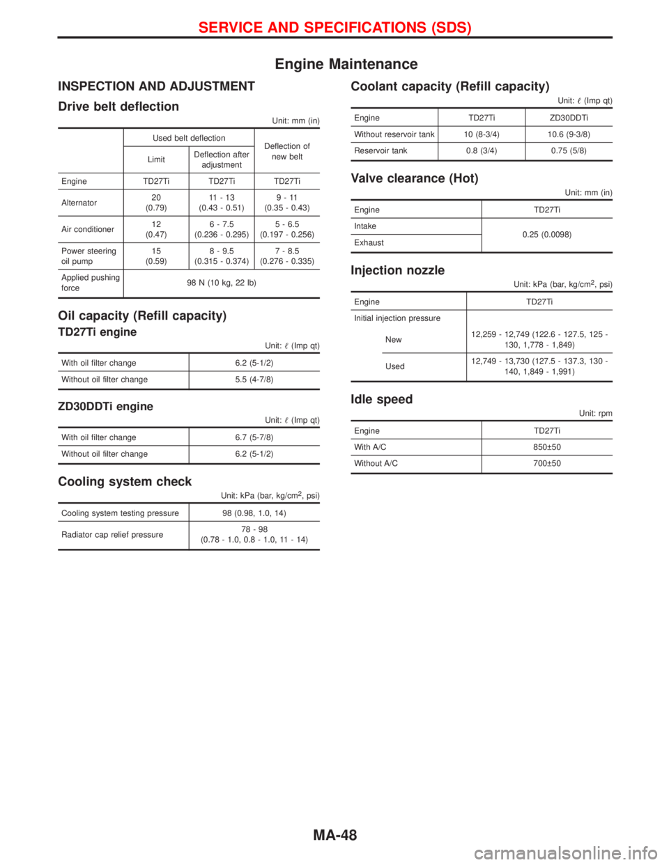
Engine Maintenance
INSPECTION AND ADJUSTMENT
Drive belt deflection
Unit: mm (in)
Used belt deflection
Deflection of
new belt
LimitDeflection after
adjustment
Engine TD27Ti TD27Ti TD27Ti
Alternator20
(0.79)11-13
(0.43 - 0.51)9-11
(0.35 - 0.43)
Air conditioner12
(0.47)6 - 7.5
(0.236 - 0.295)5 - 6.5
(0.197 - 0.256)
Power steering
oil pump15
(0.59)8 - 9.5
(0.315 - 0.374)7 - 8.5
(0.276 - 0.335)
Applied pushing
force98 N (10 kg, 22 lb)
Oil capacity (Refill capacity)
TD27Ti engine
Unit:(Imp qt)
With oil filter change 6.2 (5-1/2)
Without oil filter change 5.5 (4-7/8)
ZD30DDTi engine
Unit:(Imp qt)
With oil filter change 6.7 (5-7/8)
Without oil filter change 6.2 (5-1/2)
Cooling system check
Unit: kPa (bar, kg/cm2, psi)
Cooling system testing pressure 98 (0.98, 1.0, 14)
Radiator cap relief pressure78-98
(0.78 - 1.0, 0.8 - 1.0, 11 - 14)
Coolant capacity (Refill capacity)
Unit:(Imp qt)
Engine TD27Ti ZD30DDTi
Without reservoir tank 10 (8-3/4) 10.6 (9-3/8)
Reservoir tank 0.8 (3/4) 0.75 (5/8)
Valve clearance (Hot)
Unit: mm (in)
Engine TD27Ti
Intake
0.25 (0.0098)
Exhaust
Injection nozzle
Unit: kPa (bar, kg/cm2, psi)
Engine TD27Ti
Initial injection pressure
New12,259 - 12,749 (122.6 - 127.5, 125 -
130, 1,778 - 1,849)
Used12,749 - 13,730 (127.5 - 137.3, 130 -
140, 1,849 - 1,991)
Idle speed
Unit: rpm
Engine TD27Ti
With A/C 850 50
Without A/C 700 50
SERVICE AND SPECIFICATIONS (SDS)
MA-48
Page 1627 of 1767
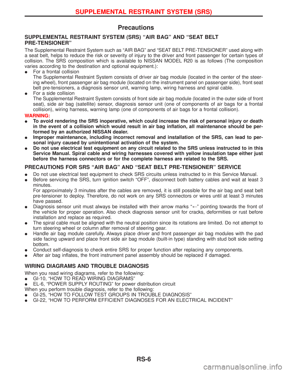
Precautions
SUPPLEMENTAL RESTRAINT SYSTEM (SRS) ªAIR BAGº AND ªSEAT BELT
PRE-TENSIONERº
The Supplemental Restraint System such as ªAIR BAGº and ªSEAT BELT PRE-TENSIONERº used along with
a seat belt, helps to reduce the risk or severity of injury to the driver and front passenger for certain types of
collision. The SRS composition which is available to NISSAN MODEL R20 is as follows (The composition
varies according to the destination and optional equipment.):
IFor a frontal collision
The Supplemental Restraint System consists of driver air bag module (located in the center of the steer-
ing wheel), front passenger air bag module (located on the instrument panel on passenger side), front seat
belt pre-tensioners, a diagnosis sensor unit, warning lamp, wiring harness and spiral cable.
IFor a side collision
The Supplemental Restraint System consists of front side air bag module (located in the outer side of front
seat), side air bag (satellite) sensor, diagnosis sensor unit (one of components of air bags for a frontal
collision), wiring harness, warning lamp (one of components of air bags for a frontal collision).
WARNING:
ITo avoid rendering the SRS inoperative, which could increase the risk of personal injury or death
in the event of a collision which would result in air bag inflation, all maintenance should be per-
formed by an authorized NISSAN dealer.
IImproper maintenance, including incorrect removal and installation of the SRS, can lead to per-
sonal injury caused by unintentional activation of the system.
IDo not use electrical test equipment on any circuit related to the SRS unless instructed to in this
Service Manual. Spiral cable and wiring harnesses covered with yellow insulation tape either just
before the harness connectors or for the complete harness are related to the SRS.
PRECAUTIONS FOR SRS ªAIR BAGº AND ªSEAT BELT PRE-TENSIONERº SERVICE
IDo not use electrical test equipment to check SRS circuits unless instructed to in this Service Manual.
IBefore servicing the SRS, turn ignition switch ªOFFº, disconnect both battery cables and wait at least 3
minutes.
For approximately 3 minutes after the cables are removed, it is still possible for the air bag and seat belt
pre-tensioner to deploy. Therefore, do not work on any SRS connectors or wires until at least 3 minutes
have passed.
IDiagnosis sensor unit must always be installed with their arrow marks ª+º pointing towards the front of
the vehicle for proper operation. Also check diagnosis sensor unit for cracks, deformities or rust before
installation and replace as required.
IThe spiral cable must be aligned with the neutral position since its rotations are limited. Do not attempt to
turn steering wheel or column after removal of steering gear.
IHandle air bag module carefully. Always place driver and front passenger air bag modules with the pad
side facing upward and place front side air bag module (built-in type) standing with stud bolt side setting
bottom.
IConduct self-diagnosis to check entire SRS for proper function after replacing any components.
IAfter air bag inflates, the front instrument panel assembly should be replaced if damaged.
WIRING DIAGRAMS AND TROUBLE DIAGNOSIS
When you read wiring diagrams, refer to the following:
IGI-10, ªHOW TO READ WIRING DIAGRAMSº
IEL-6, ªPOWER SUPPLY ROUTINGº for power distribution circuit
When you perform trouble diagnosis, refer to the following:
IGI-25, ªHOW TO FOLLOW TEST GROUPS IN TROUBLE DIAGNOSISº
IGI-22, ªHOW TO PERFORM EFFICIENT DIAGNOSES FOR AN ELECTRICAL INCIDENTº
SUPPLEMENTAL RESTRAINT SYSTEM (SRS)
RS-6