Page 1712 of 1767
STEERING SYSTEM
SECTION
ST
CONTENTS
PRECAUTIONS...............................................................2
Supplemental Restraint System (SRS)²AIR
BAG²and²SEAT BELT PRE-TENSIONER²
(Dual Air Bag System) .................................................2
Precautions for Steering System .................................2
PREPARATION................................................................3
Special Service Tools ..................................................3
ON-VEHICLE SERVICE..................................................4
Checking Steering Wheel Play ....................................4
Checking Neutral Position on Steering Wheel ............4
Front Wheel Turning Angle ..........................................4
Checking and Adjusting Drive Belts ............................4
Checking Fluid Level ...................................................4
Checking Fluid Leakage ..............................................5
Bleeding Hydraulic System..........................................5
Checking Steering Wheel Turning Force ....................6
Checking Hydraulic System.........................................7STEERING WHEEL AND STEERING COLUMN............8
Removal and Installation .............................................8
Disassembly and Assembly .......................................10
Inspection................................................................... 11
POWER STEERING GEAR...........................................12
Description .................................................................12
Removal and Installation ...........................................14
Inspection and Adjustment ........................................15
POWER STEERING OIL PUMP....................................16
Removal and Installation ...........................................16
STEERING LINKAGE....................................................17
Removal and Installation ...........................................17
Disassembly and Assembly .......................................19
Inspection...................................................................20
SERVICE DATA AND SPECIFICATIONS (SDS)..........22
General Specifications ...............................................22
Inspection and Adjustment ........................................22
Page 1717 of 1767
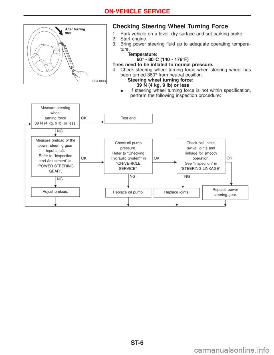
Checking Steering Wheel Turning Force
1. Park vehicle on a level, dry surface and set parking brake.
2. Start engine.
3. Bring power steering fluid up to adequate operating tempera-
ture.
Temperature:
60É - 80ÉC (140 - 176ÉF)
Tires need to be inflated to normal pressure.
4. Check steering wheel turning force when steering wheel has
been turned 360É from neutral position.
Steering wheel turning force:
39 N (4 kg, 9 lb) or less
IIf steering wheel turning force is not within specification,
perform the following inspection procedure:
E
Measure steering
wheel
turning force
39 N (4 kg, 9 lb) or less.
NG
EOK Test end
Measure preload of the
power steering gear
input shaft.
Refer to ªInspection
and Adjustmentº in
ªPOWER STEERING
GEARº.
NG
EOKCheck oil pump
pressure.
Refer to ªChecking
Hydraulic Systemº in
ªON-VEHICLE
SERVICEº.
NG
EOKCheck ball joints,
swivel joints and
linkage for smooth
operation.
See ªInspectionº in
ªSTEERING LINKAGEº.
NGOK
Adjust preload.Replace oil pump.Replace joints.Replace power
steering gear.
SST108B
H
HHHH
HHHH
ON-VEHICLE SERVICE
ST-6
Page 1723 of 1767
Description
NST028
POWER STEERING GEAR
ST-12
Page 1724 of 1767
YST021
POWER STEERING GEAR
Description (Cont'd)
ST-13
Page 1725 of 1767
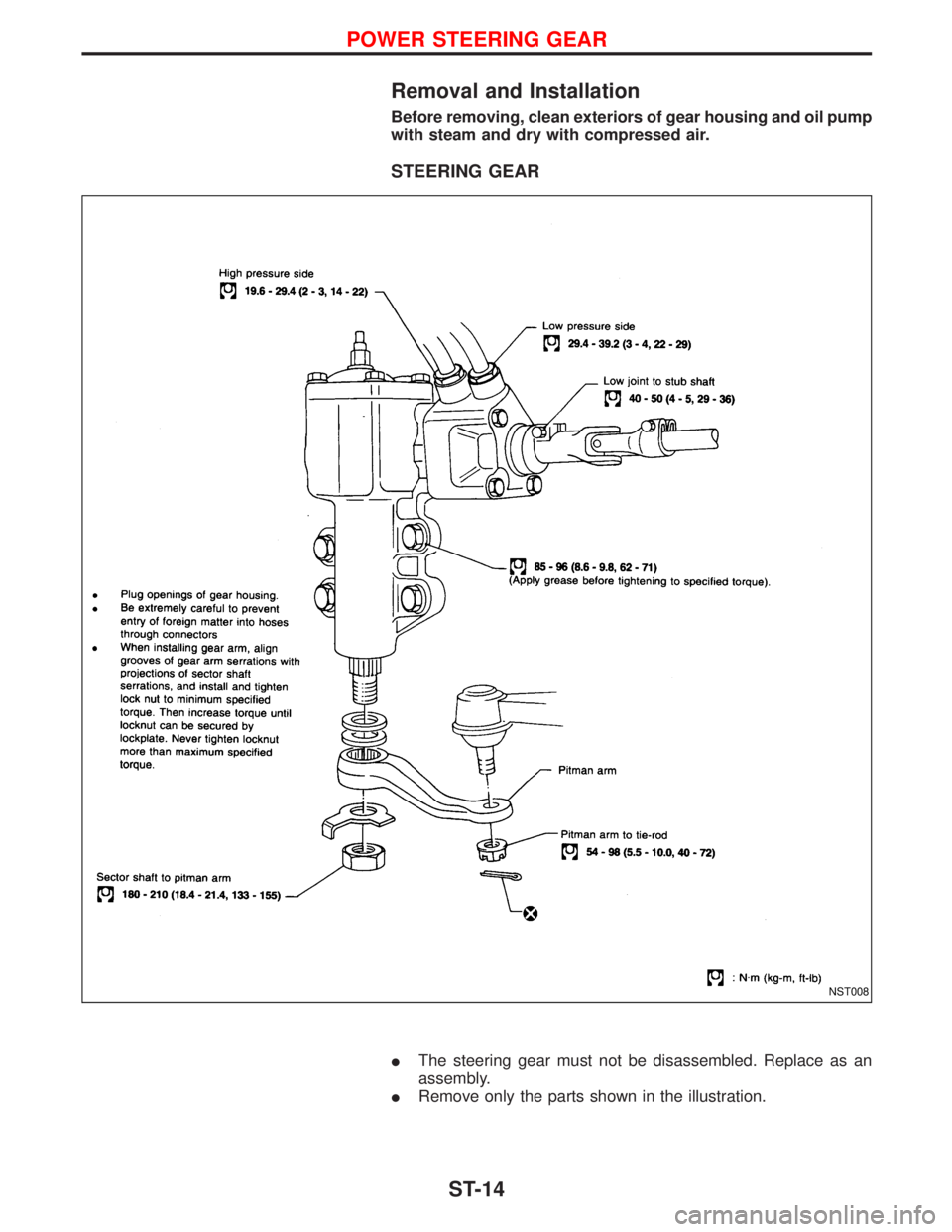
Removal and Installation
Before removing, clean exteriors of gear housing and oil pump
with steam and dry with compressed air.
STEERING GEAR
IThe steering gear must not be disassembled. Replace as an
assembly.
IRemove only the parts shown in the illustration.
NST008
POWER STEERING GEAR
ST-14
Page 1726 of 1767
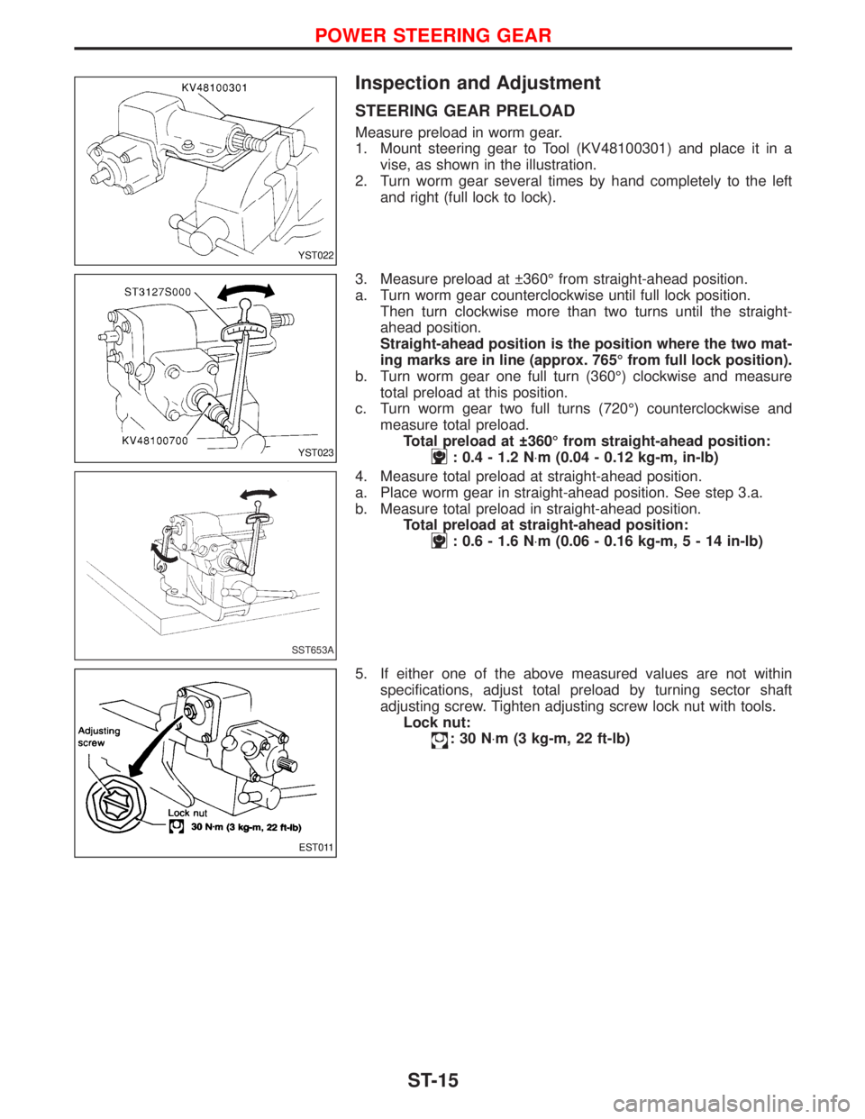
Inspection and Adjustment
STEERING GEAR PRELOAD
Measure preload in worm gear.
1. Mount steering gear to Tool (KV48100301) and place it in a
vise, as shown in the illustration.
2. Turn worm gear several times by hand completely to the left
and right (full lock to lock).
3. Measure preload at 360É from straight-ahead position.
a. Turn worm gear counterclockwise until full lock position.
Then turn clockwise more than two turns until the straight-
ahead position.
Straight-ahead position is the position where the two mat-
ing marks are in line (approx. 765É from full lock position).
b. Turn worm gear one full turn (360É) clockwise and measure
total preload at this position.
c. Turn worm gear two full turns (720É) counterclockwise and
measure total preload.
Total preload at 360É from straight-ahead position:
: 0.4 - 1.2 N×m (0.04 - 0.12 kg-m, in-lb)
4. Measure total preload at straight-ahead position.
a. Place worm gear in straight-ahead position. See step 3.a.
b. Measure total preload in straight-ahead position.
Total preload at straight-ahead position:
: 0.6 - 1.6 N×m (0.06 - 0.16 kg-m,5-14in-lb)
5. If either one of the above measured values are not within
specifications, adjust total preload by turning sector shaft
adjusting screw. Tighten adjusting screw lock nut with tools.
Lock nut:
:30N×m (3 kg-m, 22 ft-lb)
YST022
YST023
SST653A
EST011
POWER STEERING GEAR
ST-15
Page 1727 of 1767
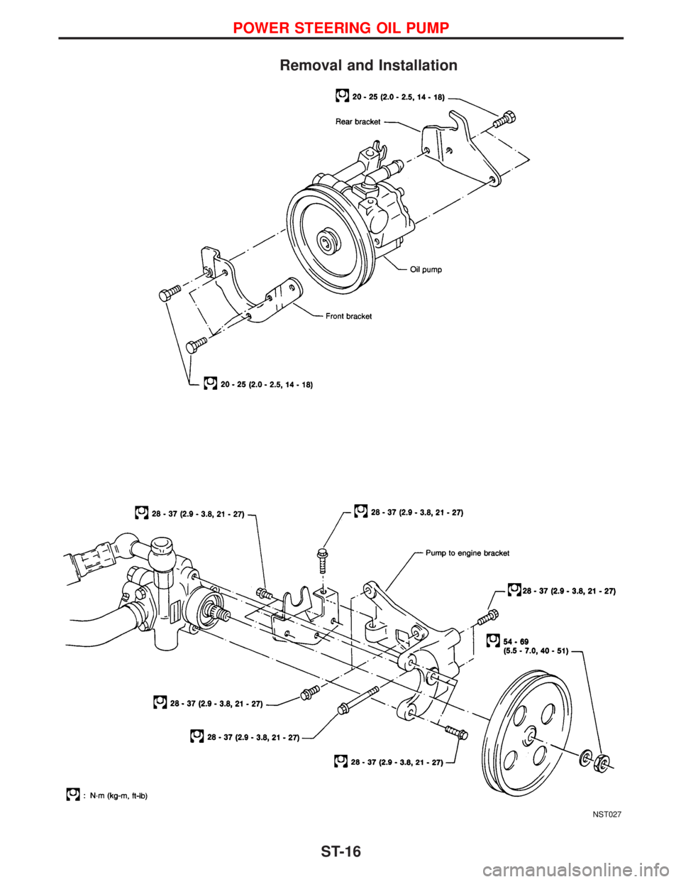
Removal and Installation
NST027
POWER STEERING OIL PUMP
ST-16
Page:
< prev 1-8 9-16 17-24