2002 NISSAN TERRANO heating
[x] Cancel search: heatingPage 758 of 1767
Component Inspection
GLOW RELAY
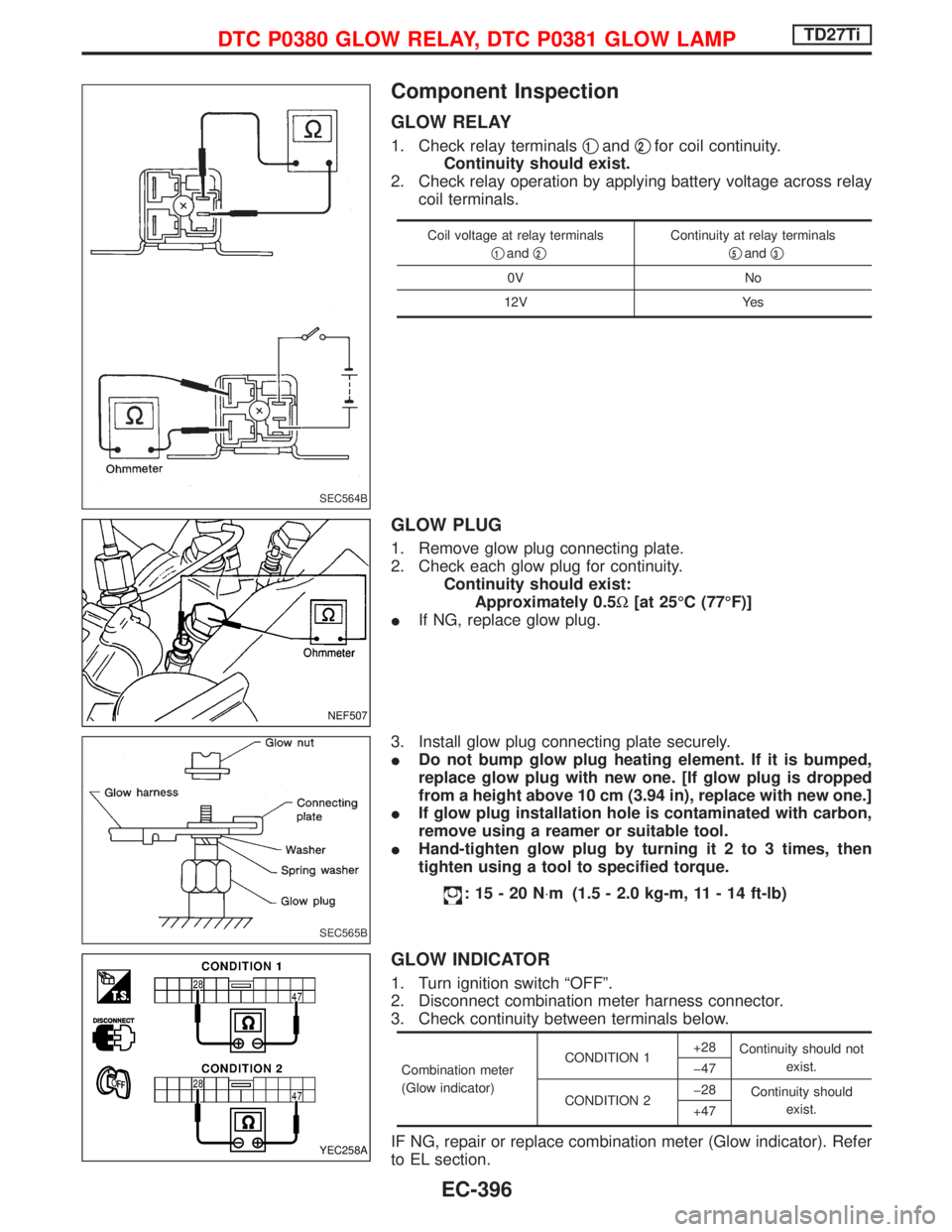
1. Check relay terminalsq1andq2for coil continuity.
Continuity should exist.
2. Check relay operation by applying battery voltage across relay
coil terminals.
Coil voltage at relay terminals
q
1andq2
Continuity at relay terminals
q
5andq3
0V No
12V Yes
GLOW PLUG
1. Remove glow plug connecting plate.
2. Check each glow plug for continuity.
Continuity should exist:
Approximately 0.5W[at 25ÉC (77ÉF)]
IIf NG, replace glow plug.
3. Install glow plug connecting plate securely.
IDo not bump glow plug heating element. If it is bumped,
replace glow plug with new one. [If glow plug is dropped
from a height above 10 cm (3.94 in), replace with new one.]
IIf glow plug installation hole is contaminated with carbon,
remove using a reamer or suitable tool.
IHand-tighten glow plug by turning it 2 to 3 times, then
tighten using a tool to specified torque.
:15-20N×m (1.5 - 2.0 kg-m, 11 - 14 ft-lb)
GLOW INDICATOR
1. Turn ignition switch ªOFFº.
2. Disconnect combination meter harness connector.
3. Check continuity between terminals below.
Combination meter
(Glow indicator)CONDITION 1+28
Continuity should not
exist.
þ47
CONDITION 2þ28
Continuity should
exist.
+47
IF NG, repair or replace combination meter (Glow indicator). Refer
to EL section.
SEC564B
NEF507
SEC565B
YEC258A
DTC P0380 GLOW RELAY, DTC P0381 GLOW LAMPTD27Ti
EC-396
Page 780 of 1767
Description
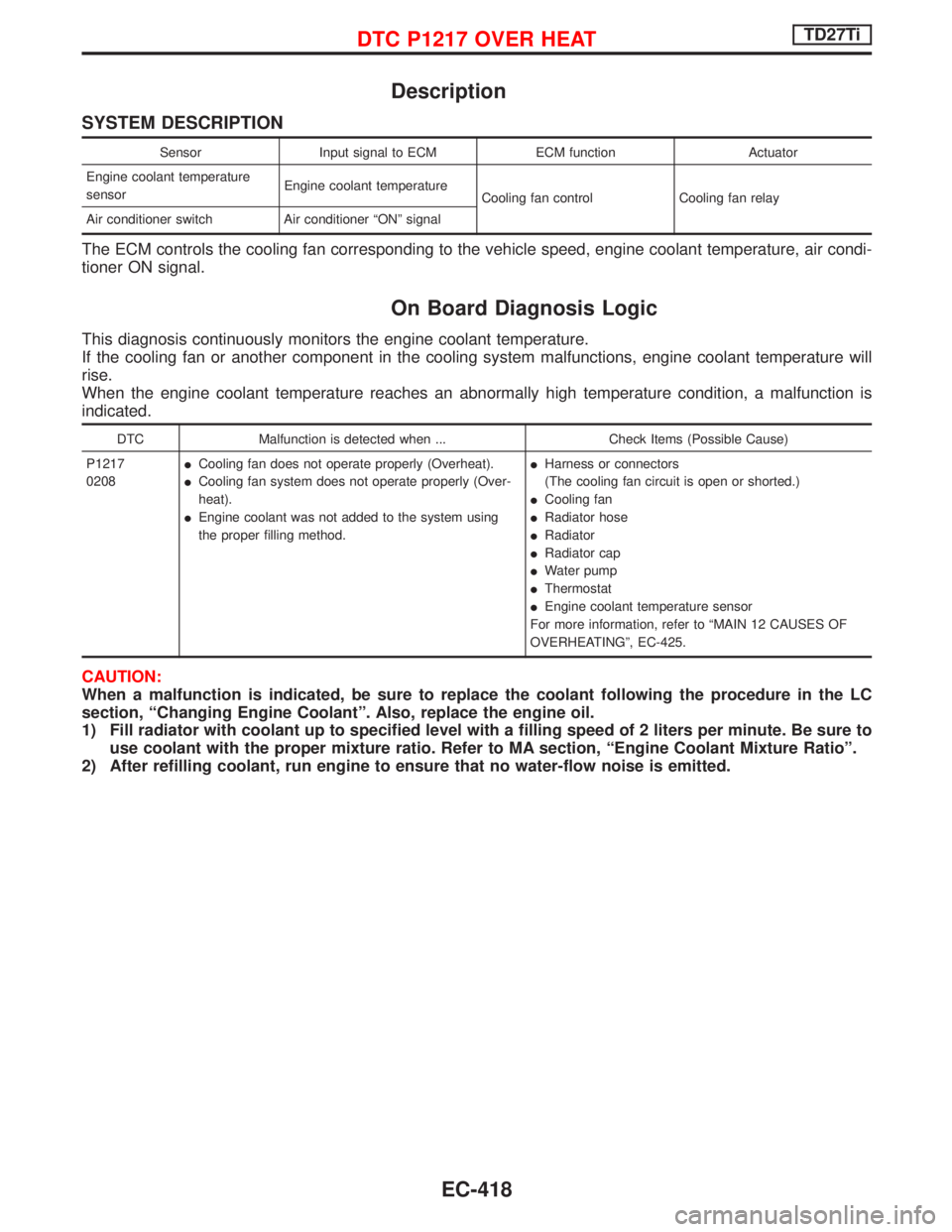
SYSTEM DESCRIPTION
Sensor Input signal to ECM ECM function Actuator
Engine coolant temperature
sensorEngine coolant temperature
Cooling fan control Cooling fan relay
Air conditioner switch Air conditioner ªONº signal
The ECM controls the cooling fan corresponding to the vehicle speed, engine coolant temperature, air condi-
tioner ON signal.
On Board Diagnosis Logic
This diagnosis continuously monitors the engine coolant temperature.
If the cooling fan or another component in the cooling system malfunctions, engine coolant temperature will
rise.
When the engine coolant temperature reaches an abnormally high temperature condition, a malfunction is
indicated.
DTC Malfunction is detected when ... Check Items (Possible Cause)
P1217
0208ICooling fan does not operate properly (Overheat).
ICooling fan system does not operate properly (Over-
heat).
IEngine coolant was not added to the system using
the proper filling method.IHarness or connectors
(The cooling fan circuit is open or shorted.)
ICooling fan
IRadiator hose
IRadiator
IRadiator cap
IWater pump
IThermostat
IEngine coolant temperature sensor
For more information, refer to ªMAIN 12 CAUSES OF
OVERHEATINGº, EC-425.
CAUTION:
When a malfunction is indicated, be sure to replace the coolant following the procedure in the LC
section, ªChanging Engine Coolantº. Also, replace the engine oil.
1) Fill radiator with coolant up to specified level with a filling speed of 2 liters per minute. Be sure to
use coolant with the proper mixture ratio. Refer to MA section, ªEngine Coolant Mixture Ratioº.
2) After refilling coolant, run engine to ensure that no water-flow noise is emitted.
DTC P1217 OVER HEATTD27Ti
EC-418
Page 786 of 1767
qc
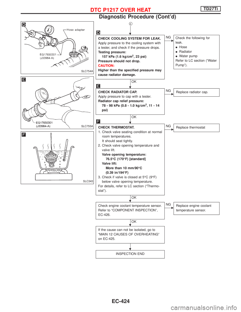
CHECK COOLING SYSTEM FOR LEAK.
Apply pressure to the cooling system with
a tester, and check if the pressure drops.
Testing pressure:
157 kPa (1.6 kg/cm
2, 23 psi)
Pressure should not drop.
CAUTION:
Higher than the specified pressure may
cause radiator damage.
OK
ENG
Check the following for
leak.
IHose
IRadiator
IWater pump
Refer to LC section (ªWater
Pumpº).
CHECK RADIATOR CAP.
Apply pressure to cap with a tester.
Radiator cap relief pressure:
78 - 98 kPa (0.8 - 1.0 kg/cm
2,11-14
psi)
OK
ENG
Replace radiator cap.
CHECK THERMOSTAT.
1. Check valve seating condition at normal
room temperatures.
It should seat tightly.
2. Check valve opening temperature and
valve lift.
Valve opening temperature:
76.5ÉC (170ÉF) [standard]
Valve lift:
More than 10 mm/90ÉC
(0.39 in/194ÉF)
3. Check if valve is closed at 5ÉC (9ÉF)
below valve opening temperature.
For details, refer to LC section (ªThermo-
statº).
OK
ENG
Replace thermostat
Check engine coolant temperature sensor.
Refer to ªCOMPONENT INSPECTIONº,
EC-426.
OK
ENG
Replace engine coolant
temperature sensor.
If the cause can not be isolated, go to
ªMAIN 12 CAUSES OF OVERHEATINGº
on EC-425.
INSPECTION END
SLC754A
SLC755A
SLC343
H
H
H
H
H
H
DTC P1217 OVER HEATTD27Ti
Diagnostic Procedure (Cont'd)
EC-424
Page 787 of 1767
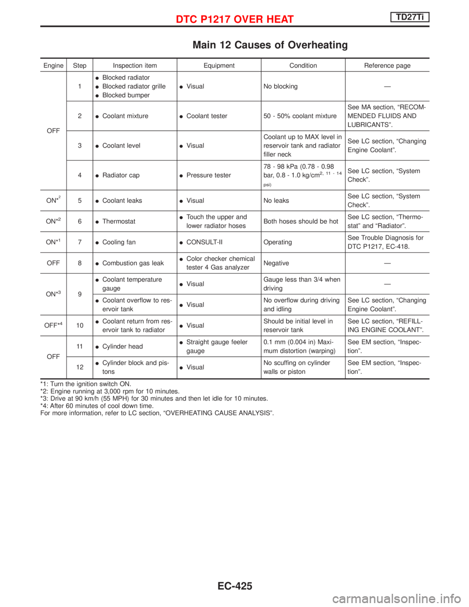
Main 12 Causes of Overheating
Engine Step Inspection item Equipment Condition Reference page
OFF1IBlocked radiator
IBlocked radiator grille
IBlocked bumperIVisual No blocking Ð
2ICoolant mixtureICoolant tester 50 - 50% coolant mixtureSee MA section, ªRECOM-
MENDED FLUIDS AND
LUBRICANTSº.
3ICoolant levelIVisualCoolant up to MAX level in
reservoir tank and radiator
filler neckSee LC section, ªChanging
Engine Coolantº.
4IRadiator capIPressure tester78 - 98 kPa (0.78 - 0.98
bar, 0.8 - 1.0 kg/cm
2,11-14
psi)See LC section, ªSystem
Checkº.
ON*
25ICoolant leaksIVisual No leaksSee LC section, ªSystem
Checkº.
ON*
26IThermostatITouch the upper and
lower radiator hosesBoth hoses should be hotSee LC section, ªThermo-
statº and ªRadiatorº.
ON*
17ICooling fanICONSULT-II OperatingSee Trouble Diagnosis for
DTC P1217, EC-418.
OFF 8ICombustion gas leakIColor checker chemical
tester 4 Gas analyzerNegative Ð
ON*
39ICoolant temperature
gaugeIVisualGauge less than 3/4 when
drivingÐ
ICoolant overflow to res-
ervoir tankIVisualNo overflow during driving
and idlingSee LC section, ªChanging
Engine Coolantº.
OFF*
410ICoolant return from res-
ervoir tank to radiatorIVisualShould be initial level in
reservoir tankSee LC section, ªREFILL-
ING ENGINE COOLANTº.
OFF11ICylinder headIStraight gauge feeler
gauge0.1 mm (0.004 in) Maxi-
mum distortion (warping)See EM section, ªInspec-
tionº.
12ICylinder block and pis-
tonsIVisualNo scuffing on cylinder
walls or pistonSee EM section, ªInspec-
tionº.
*1: Turn the ignition switch ON.
*2: Engine running at 3,000 rpm for 10 minutes.
*3: Drive at 90 km/h (55 MPH) for 30 minutes and then let idle for 10 minutes.
*4: After 60 minutes of cool down time.
For more information, refer to LC section, ªOVERHEATING CAUSE ANALYSISº.
DTC P1217 OVER HEATTD27Ti
EC-425
Page 1172 of 1767
Engine room (Left)
3. Remove air duct and air cleaner case.
4. Disconnect vacuum hose to the vehicle on the engine.
5. Disconnect harness connectors from alternator and air com-
pressor.
6. Remove alternator.
7. After removing refrigerant, remove pipes of air compressor and
inlet/outlet.
8. Disconnect heating hose, install blank cap to hose to prevent
coolant from leaking.
9. Remove heating pipe.
10. Remove heat insulator.
11. Remove catalytic converter.
Engine room (Right)
12. Remove power steering reservoir tank from bracket, and fix it
to the vehicle with a rope.
CAUTION:
Keep the reservoir tank level when fixing to prevent oil leak.
13. Remove fuel feed and return hoses.
CAUTION:
Install blank caps immediately to avoid fuel leakage.
14. Remove all harness connectors on the engine, and move har-
nesses to the side of the vehicle.
Vehicle underfloor
15. Remove starter motor.
16. Detach A/T oil cooler pipes from oil pan. (A/T model)
17. Remove rear propeller shaft.
18. Remove mounting bolts to secure the engine to transmission.
1) Remove torque converter installation bolt. (A/T model)
2) Lift transmission bottom with transmission jack, and remove
rear mount members from the vehicle.
3) Lower transmission with the jack, and remove upper mounting
bolts securing the engine to transmission.
4) Lift transmission with the jack, and reinstall rear mount mem-
bers to the vehicle.
5) Position the jack to the front side of transmission.
6) Remove remaining mounting bolts securing the engine to trans-
mission.
Removal operation
19. Remove air conditioner high pressure pipes at the rear of the
engine room.
IThis is due to some inconvenience in the rear slinger installa-
tion.
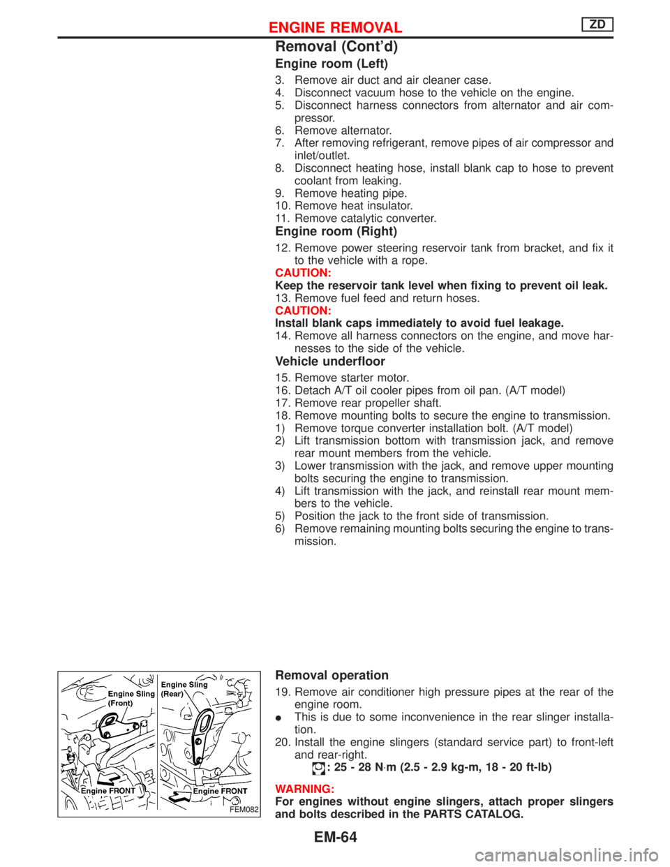
20. Install the engine slingers (standard service part) to front-left
and rear-right.
:25-28N×m (2.5 - 2.9 kg-m, 18 - 20 ft-lb)
WARNING:
For engines without engine slingers, attach proper slingers
and bolts described in the PARTS CATALOG.
FEM082
ENGINE REMOVALZD
Removal (Cont'd)
EM-64
Page 1321 of 1767
Precautions for Fuel
DIESEL ENGINE*:
Diesel fuel of at least 50 cetane for ZD30DDTi engine.
* If two types of diesel fuel are available, use summer or winter
fuel properly according to the following temperature conditions.
IAbove þ7ÉC (20ÉF) ... Summer type diesel fuel.
IBelow þ7ÉC (20ÉF) ... Winter type diesel fuel.
CAUTION:
IDo not use home heating oil, gasoline, or other alternate
fuels in your diesel engine. The use of those can cause
engine damage.
IDo not use summer fuel at temperature below þ7ÉC (20ÉF).
The cold temperature will cause wax to form in the fuel. As
a result, it may prevent the engine from running smoothly.
IDo not add gasoline or other alternate fuels to diesel fuel.
Precautions for Engine Oils
Prolonged and repeated contact with mineral oil will result in the
removal of natural fats from the skin, leading to dryness, irritation
and dermatitis. In addition, used engine oil contains potentially
harmful contaminants which may cause skin cancer. Adequate
means of skin protection and washing facilities must be provided.
HEALTH PROTECTION PRECAUTIONS
1. Avoid prolonged and repeated contact with oils, particularly
used engine oils.
2. Wear protective clothing, including impervious gloves where
practicable.
3. Do not put oily rags in pockets.
4. Avoid contaminating clothes, particularly underwear, with oil.
5. Heavily soiled clothing and oil-impregnated footwear should not
be worn. Overalls must be cleaned regularly.
6. First Aid treatment should be obtained immediately for open
cuts and wounds.
7. Use barrier creams, applying them before each work period, to
help the removal of oil from the skin.
8. Wash with soap and water to ensure all oil is removed (skin
cleansers and nail brushes will help). Preparations containing
lanolin replace the natural skin oils which have been removed.
9. Do not use petrol, kerosine, diesel fuel, gas oil, thinners or sol-
vents for cleaning skin.
10. If skin disorders develop, obtain medical advice without delay.
11. Where practicable, degrease components prior to handling.
12. Where there is a risk of eye contact, eye protection should be
worn, for example, chemical goggles or face shields; in addition
an eye wash facility should be provided.
(For the United Kingdom, see also HSE Cautionary Notice SHW
397 ªEffects of Mineral Oil on the Skinº.)
ENVIRONMENTAL PROTECTION PRECAUTIONS
Burning used engine oil in small space heaters or boilers can be
recommended only for units of approved design. The heating sys-
tem must meet the requirements of HM Inspectorate of Pollution for
small burners of less than 0.4 MW. If in doubt check with the
appropriate local authority and/or manufacturer of the approved
appliance.
PRECAUTIONS
GI-6
Page 1339 of 1767
Engine compartment
There are several reasons a vehicle or engine vibration could
cause an electrical complaint. Some of the things to check for are:
IConnectors not fully seated.
IWiring harness not long enough and is being stressed due to
engine vibrations or rocking.
IWires laying across brackets or moving components.
ILoose, dirty or corroded ground wires.
IWires routed too close to hot components.
To inspect components under the hood, start by verifying the integ-
rity of ground connections. (Refer to GROUND INSPECTION
described later.) First check that the system is properly grounded.
Then check for loose connection bygently shakingthe wiring or
components as previously explained. Using the wiring diagrams
inspect the wiring for continuity.
Behind the instrument panel
An improperly routed or improperly clamped harness can become
pinched during accessory installation. Vehicle vibration can aggra-
vate a harness which is routed along a bracket or near a screw.
Under seating areas
An unclamped or loose harness can cause wiring to be pinched by
seat components (such as slide guides) during vehicle vibration. If
the wiring runs under seating areas, inspect wire routing for pos-
sible damage or pinching.
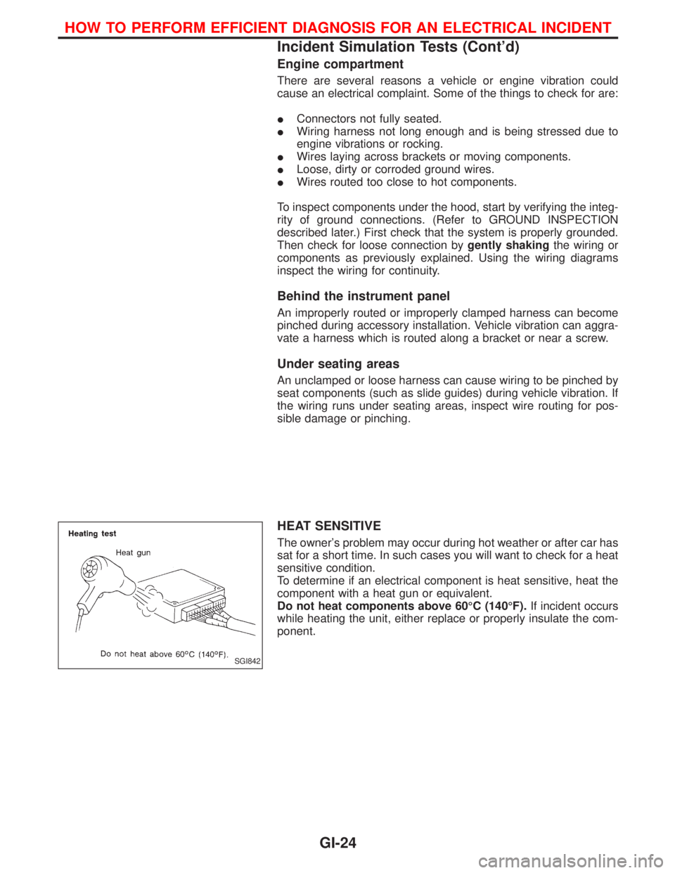
HEAT SENSITIVE
The owner's problem may occur during hot weather or after car has
sat for a short time. In such cases you will want to check for a heat
sensitive condition.
To determine if an electrical component is heat sensitive, heat the
component with a heat gun or equivalent.
Do not heat components above 60ÉC (140ÉF).If incident occurs
while heating the unit, either replace or properly insulate the com-
ponent.
SGI842
HOW TO PERFORM EFFICIENT DIAGNOSIS FOR AN ELECTRICAL INCIDENT
Incident Simulation Tests (Cont'd)
GI-24