Page 1048 of 1672
BRAKES
DESCRIPTION AND OPERATION 70-3
1ABS sensor
2ABS modulator
3Return pump relay
4SLABS ECU
5Brake lamp relay
6Centre high mounted stop lamp
7LH brake lamp
8RH brake lamp
9Instrument pack
10Body control unit
11Reverse lamp switch (manual gearbox)
12Diagnostic socket
13HDC switch
14Transmission high/low switch
15Centre differential lock switch
16Engine control module
17Battery power supply
18Ignition power supply
Page 1070 of 1672
BRAKES
DESCRIPTION AND OPERATION 70-25
DESCRIPTION AND OPERAT ION
Handbrake component layout
1Warning switch
2Handbrake lever
3Cable
4Protective sleeve
5Drum brake
6'C' clip
7Threaded sleeve
8Adjuster wheel
9Base plate
10Transmission tunnel
Page 1071 of 1672

BRAKES
70-26 DESCRIPTION AND OPERATION
Description
General
The handbrake consists of a drum brake, installed on the rear of the transfer box, operated by a cable connected to
a handbrake lever between the front seats.
Handbrake lever
The handbrake lever is mounted on a base plate which attaches to the transmission tunnel. A conventional ratchet
and thumb operated release button are incorporated for locking and unlocking the lever. A warning switch on the base
of the lever operates the brake warning lamp in the instrument pack. While the handbrake is applied the warning
switch connects an earth to the instrument pack which, if the ignition is on, illuminates the brake warning lamp. In
some markets, the instrument pack performs a bulb check of the brake warning lamp each time the ignition is switched
on.
Cable
The handbrake cable consists of inner and outer cables installed between the handbrake lever and the drum brake.
A protective sleeve is installed on the cable to protect the cable from heat from the exhaust system. Handbrake
adjustment is provided by a threaded sleeve installed on the outer cable where it locates in the handbrake lever.
Turning an adjuster wheel, which is keyed to the threaded sleeve and secured by a 'C' clip, alters the effective length
of the outer sleeve and consequently changes the handbrake lever movement needed to apply the drum brake.
Page 1081 of 1672

BRAKES
70-36 REPAIRS
Cable - handbrake
$% 70.35.25
Remove
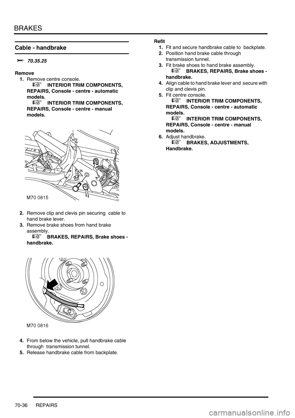
1.Remove centre console.
+ INTERIOR TRIM COMPONENTS,
REPAIRS, Console - centre - automatic
models.
+ INTERIOR TRIM COMPONENTS,
REPAIRS, Console - centre - manual
models.
2.Remove clip and clevis pin securing cable to
hand brake lever.
3.Remove brake shoes from hand brake
assembly.
+ BRAKES, REPAIRS, Brake shoes -
handbrake.
4.From below the vehicle, pull handbrake cable
through transmission tunnel.
5.Release handbrake cable from backplate. Refit
1.Fit and secure handbrake cable to backplate.
2.Position hand brake cable through
transmission tunnel.
3.Fit brake shoes to hand brake assembly.
+ BRAKES, REPAIRS, Brake shoes -
handbrake.
4.Align cable to hand brake lever and secure with
clip and clevis pin.
5.Fit centre console.
+ INTERIOR TRIM COMPONENTS,
REPAIRS, Console - centre - automatic
models.
+ INTERIOR TRIM COMPONENTS,
REPAIRS, Console - centre - manual
models.
6.Adjust handbrake.
+ BRAKES, ADJUSTMENTS,
Handbrake.
Page 1103 of 1672

RESTRAINT SYSTEMS
75-8 DESCRIPTION AND OPERATION
Diagnostic and Control Unit (DCU)
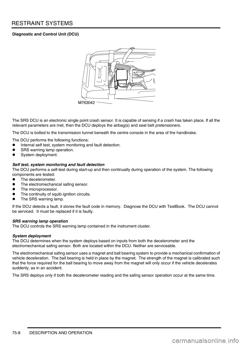
The SRS DCU is an electronic single point crash sensor. It is capable of sensing if a crash has taken place. If all the
relevant parameters are met, then the DCU deploys the airbag(s) and seat belt pretensioners.
The DCU is bolted to the transmission tunnel beneath the centre console in the area of the handbrake.
The DCU performs the following functions:
lInternal self test, system monitoring and fault detection.
lSRS warning lamp operation.
lSystem deployment.
Self test, system monitoring and fault detection
The DCU performs a self-test during start-up and then continually during operation of the system. The following
components are tested:
lThe decelerometer.
lThe electromechanical safing sensor.
lThe microprocessor.
lThe continuity of squib ignition circuits.
lThe SRS warning lamp.
If the DCU detects a fault, it stores the fault code in memory. Diagnose the DCU with TestBook. The DCU cannot
be serviced. It must be replaced if it is faulty.
SRS warning lamp operation
The DCU controls the SRS warning lamp contained in the instrument cluster.
System deployment
The DCU determines when the system deploys based on inputs from both the decelerometer and the
electromechanical safing sensor. Both are located within the DCU. Neither are serviceable.
The electromechanical safing sensor uses a magnet and ball bearing system to provide a mechanical confirmation of
vehicle deceleration. The ball bearing is held in place by the magnet. The strength of the magnet is calibrated such
that the force required for the ball bearing to move away from the magnet will only occur if the vehicle decelerates
suddenly, as in an accident.
The SRS deploys only if both the decelerometer reading and the safing sensor operation occur at the same time.
Page 1158 of 1672
INTERIOR TRIM COMPONENTS
REPAIRS 76-3-5
5. Models with base trim: Remove rubber mat
from centre console and remove cover plate
from switch pack.
6. Models with base trim: Remove 4 screws
securing switch pack to centre console,
disconnect multiplugs and remove switch pack.7. Models with veneer trim: Release veneered
console cover and remove cigar lighter
element. Disconnect multiplugs from switch
pack and remove veneered console cover.
8.Remove 2 bolts securing forward edge of
console to transmission tunnel.
Page 1159 of 1672

INTERIOR TRIM COMPONENTS
76-3-6 REPAIRS
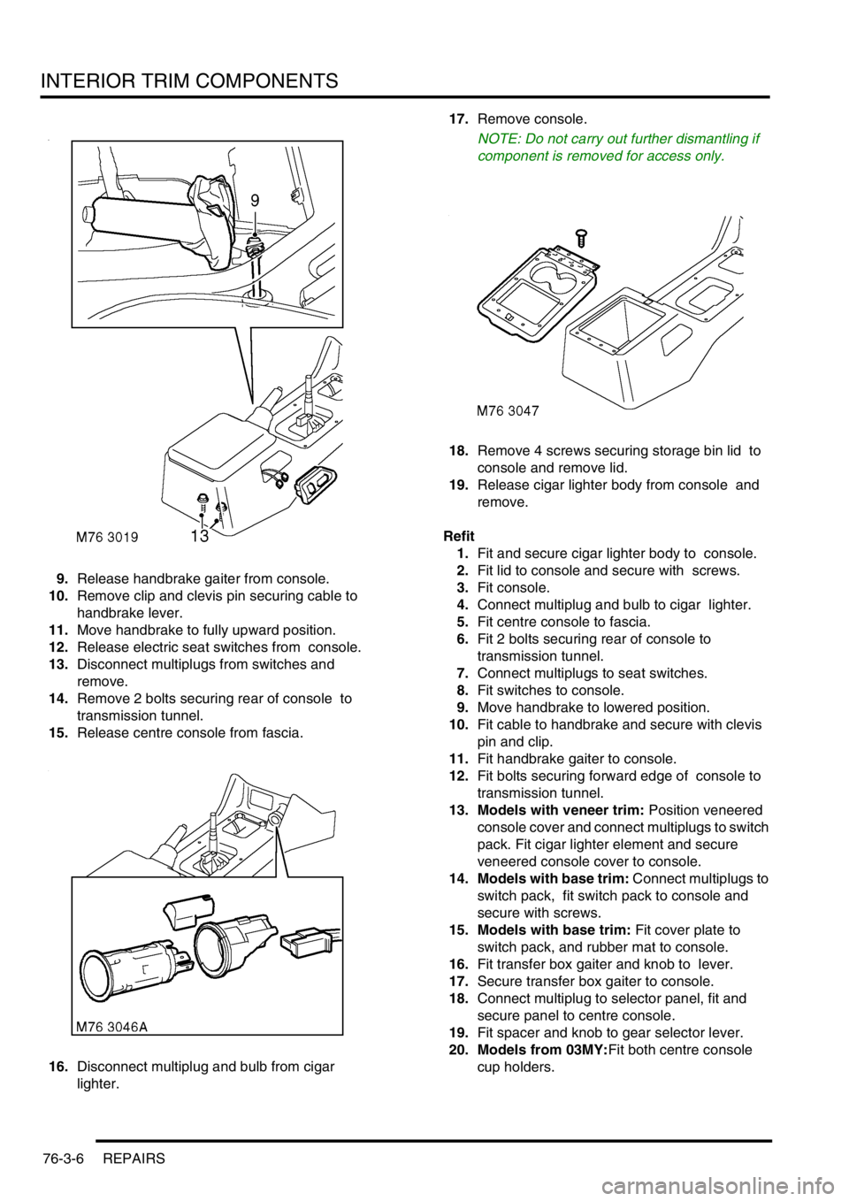
9.Release handbrake gaiter from console.
10.Remove clip and clevis pin securing cable to
handbrake lever.
11.Move handbrake to fully upward position.
12.Release electric seat switches from console.
13.Disconnect multiplugs from switches and
remove.
14.Remove 2 bolts securing rear of console to
transmission tunnel.
15.Release centre console from fascia.
16.Disconnect multiplug and bulb from cigar
lighter. 17.Remove console.
NOTE: Do not carry out further dismantling if
component is removed for access only.
18.Remove 4 screws securing storage bin lid to
console and remove lid.
19.Release cigar lighter body from console and
remove.
Refit
1.Fit and secure cigar lighter body to console.
2.Fit lid to console and secure with screws.
3.Fit console.
4.Connect multiplug and bulb to cigar lighter.
5.Fit centre console to fascia.
6.Fit 2 bolts securing rear of console to
transmission tunnel.
7.Connect multiplugs to seat switches.
8.Fit switches to console.
9.Move handbrake to lowered position.
10.Fit cable to handbrake and secure with clevis
pin and clip.
11.Fit handbrake gaiter to console.
12.Fit bolts securing forward edge of console to
transmission tunnel.
13. Models with veneer trim: Position veneered
console cover and connect multiplugs to switch
pack. Fit cigar lighter element and secure
veneered console cover to console.
14. Models with base trim: Connect multiplugs to
switch pack, fit switch pack to console and
secure with screws.
15. Models with base trim: Fit cover plate to
switch pack, and rubber mat to console.
16.Fit transfer box gaiter and knob to lever.
17.Secure transfer box gaiter to console.
18.Connect multiplug to selector panel, fit and
secure panel to centre console.
19.Fit spacer and knob to gear selector lever.
20. Models from 03MY:Fit both centre console
cup holders.
Page 1161 of 1672
INTERIOR TRIM COMPONENTS
76-3-8 REPAIRS
6. Models with veneer trim: Release veneered
console cover from console and remove cigar
lighter element. Disconnect multiplugs from
switch pack and remove veneered console
cover.
7.Remove 2 bolts securing forward edge of
console to transmission tunnel. 8.Release handbrake gaiter from console.
9.Remove clip and clevis pin securing cable to
handbrake.
10.Move handbrake to fully upward position.
11.Release electric seat switches from console.
12.Disconnect multiplugs from switches and
remove.
13.Remove 2 bolts securing rear of console to
transmission tunnel.
14.Release centre console from fascia.
15.Disconnect multiplug and bulb from cigar
lighter.