2002 LAND ROVER DISCOVERY headlamp
[x] Cancel search: headlampPage 1460 of 1672
LIGHTING
REPAIRS 86-2-5
Headlamp - from 03MY
$% 86.40.49
Remove
1.Remove front grille.
+ EXTERIOR FITTINGS, REPAIRS,
Grille - front - from 03MY.
2.Protect bumper.
CAUTION: Always protect paintwork when
removing or refitting any body trims or
bumpers.
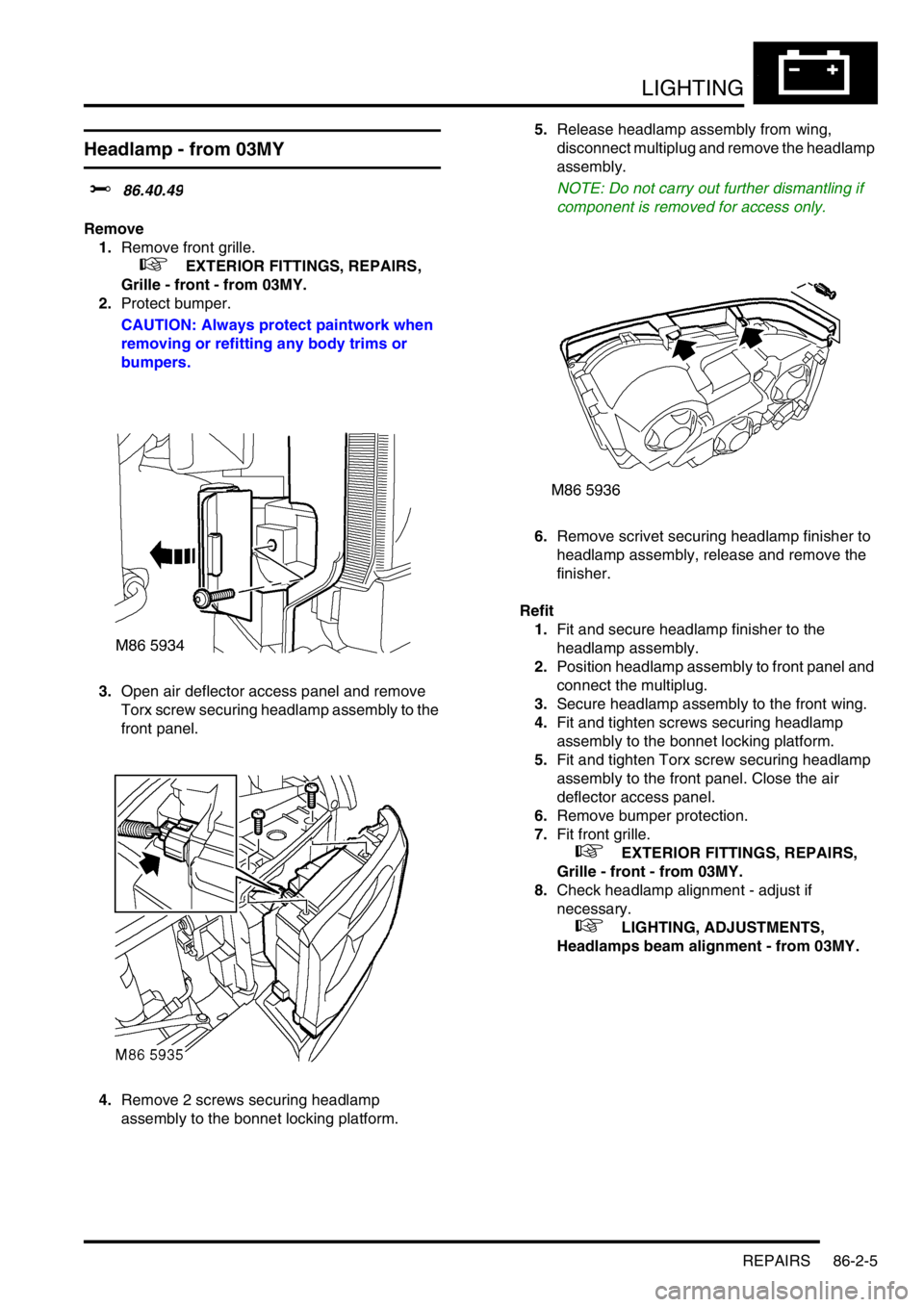
3.Open air deflector access panel and remove
Torx screw securing headlamp assembly to the
front panel.
4.Remove 2 screws securing headlamp
assembly to the bonnet locking platform.5.Release headlamp assembly from wing,
disconnect multiplug and remove the headlamp
assembly.
NOTE: Do not carry out further dismantling if
component is removed for access only.
6.Remove scrivet securing headlamp finisher to
headlamp assembly, release and remove the
finisher.
Refit
1.Fit and secure headlamp finisher to the
headlamp assembly.
2.Position headlamp assembly to front panel and
connect the multiplug.
3.Secure headlamp assembly to the front wing.
4.Fit and tighten screws securing headlamp
assembly to the bonnet locking platform.
5.Fit and tighten Torx screw securing headlamp
assembly to the front panel. Close the air
deflector access panel.
6.Remove bumper protection.
7.Fit front grille.
+ EXTERIOR FITTINGS, REPAIRS,
Grille - front - from 03MY.
8.Check headlamp alignment - adjust if
necessary.
+ LIGHTING, ADJUSTMENTS,
Headlamps beam alignment - from 03MY.
Page 1464 of 1672
LIGHTING
REPAIRS 86-2-9
Motor - headlamp levelling
$% 86.41.16
Remove
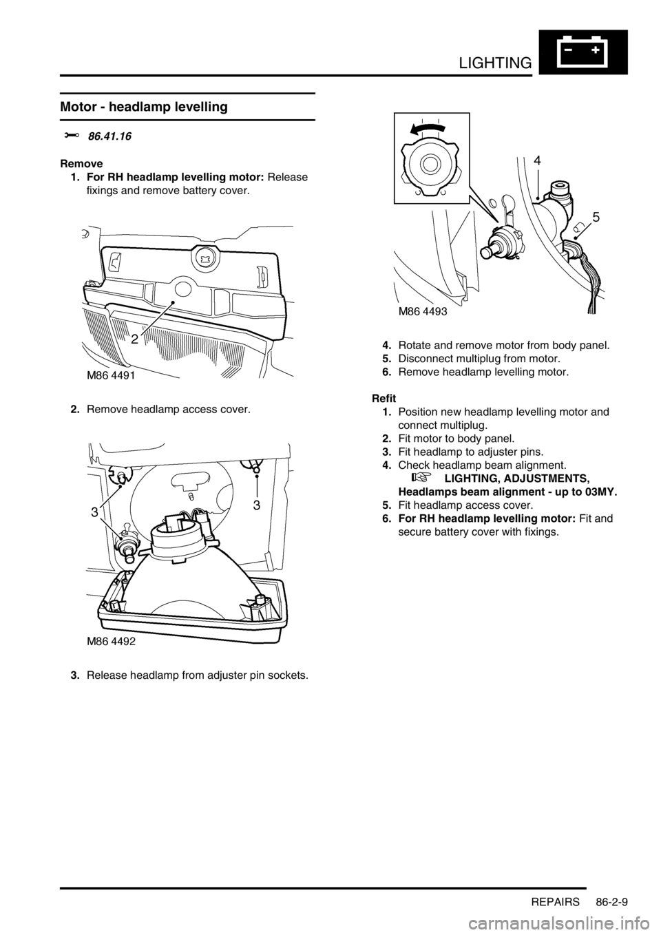
1. For RH headlamp levelling motor: Release
fixings and remove battery cover.
2.Remove headlamp access cover.
3.Release headlamp from adjuster pin sockets. 4.Rotate and remove motor from body panel.
5.Disconnect multiplug from motor.
6.Remove headlamp levelling motor.
Refit
1.Position new headlamp levelling motor and
connect multiplug.
2.Fit motor to body panel.
3.Fit headlamp to adjuster pins.
4.Check headlamp beam alignment.
+ LIGHTING, ADJUSTMENTS,
Headlamps beam alignment - up to 03MY.
5.Fit headlamp access cover.
6. For RH headlamp levelling motor: Fit and
secure battery cover with fixings.
Page 1472 of 1672
BODY CONTROL UNIT
DESCRIPTION AND OPERATION 86-3-3
BCU outputs
The BCU processes the input signals it receives and uses the information to determine the control outputs that need
to be established for any given set of conditions. The BCU provides controlled outputs for the following systems:
lInterior courtesy lamps.
lFuel flap release actuator.
lAnti-theft status LED.
lEngine Control Module.
lDoor lock actuators.
lDirection indicators and hazard warning lamps.
lHeadlamps.
lAlarm sounder.
lVehicle horns.
lBattery backed sounder.
lStarter relay.
lPassive re-mobilisation exciter coil.
Simultaneous switching of outputs in different units is limited by the bus transfer time, but the skew is no longer than
100 ms for either the BCU or the IDM. When the processor is reset, all outputs are switched off until the inputs have
been read for the first time to check current condition.
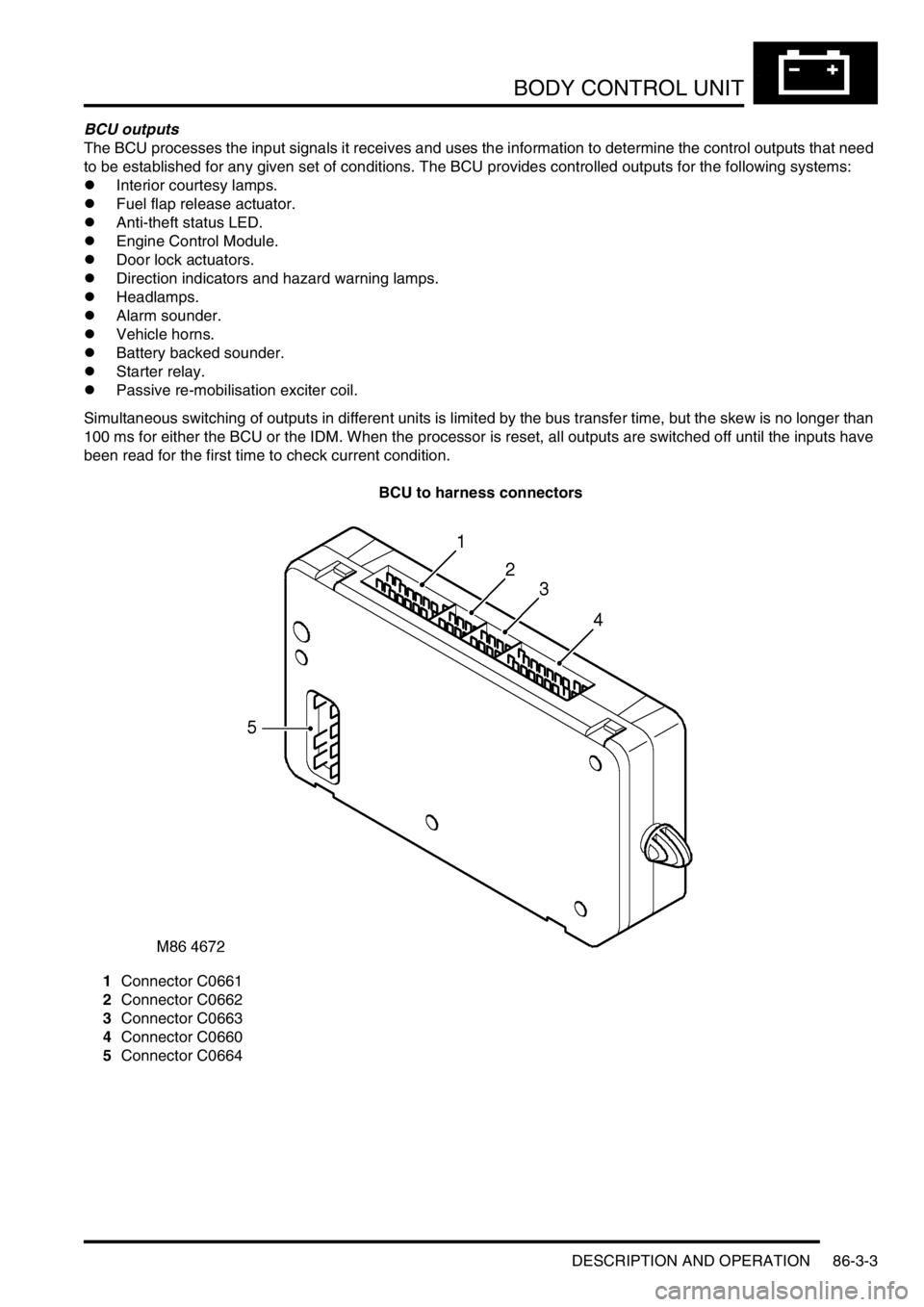
BCU to harness connectors
1Connector C0661
2Connector C0662
3Connector C0663
4Connector C0660
5Connector C0664
Page 1475 of 1672
BODY CONTROL UNIT
86-3-6 DESCRIPTION AND OPERATION
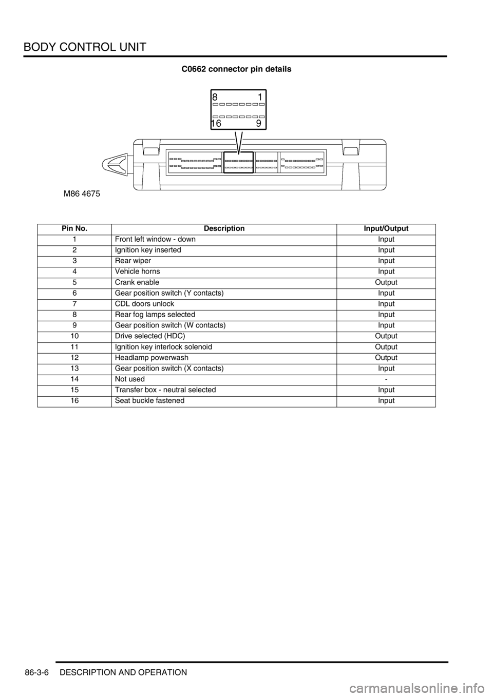
C0662 connector pin details
Pin No. Description Input/Output
1 Front left window - down Input
2 Ignition key inserted Input
3 Rear wiper Input
4 Vehicle horns Input
5 Crank enable Output
6 Gear position switch (Y contacts) Input
7 CDL doors unlock Input
8 Rear fog lamps selected Input
9 Gear position switch (W contacts) Input
10 Drive selected (HDC) Output
11 Ignition key interlock solenoid Output
12 Headlamp powerwash Output
13 Gear position switch (X contacts) Input
14 Not used-
15 Transfer box - neutral selected Input
16 Seat buckle fastened Input
Page 1477 of 1672
BODY CONTROL UNIT
86-3-8 DESCRIPTION AND OPERATION
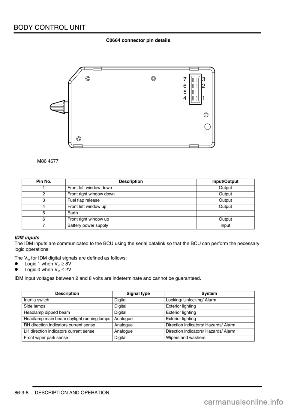
C0664 connector pin details
IDM inputs
The IDM inputs are communicated to the BCU using the serial datalink so that the BCU can perform the necessary
logic operations:
The V
in for IDM digital signals are defined as follows:
lLogic 1 when V
in ≥ 8V.
lLogic 0 when V
in ≤ 2V.
IDM input voltages between 2 and 8 volts are indeterminate and cannot be guaranteed.
Pin No. Description Input/Output
1 Front left window down Output
2 Front right window down Output
3 Fuel flap release Output
4 Front left window up Output
5Earth-
6 Front right window up Output
7 Battery power supply Input
Description Signal type System
Inertia switch Digital Locking/ Unlocking/ Alarm
Side lamps Digital Exterior lighting
Headlamp dipped beam Digital Exterior lighting
Headlamp main beam daylight running lamps Analogue Exterior lighting
RH direction indicators current sense Analogue Direction indicators/ Hazards/ Alarm
LH direction indicators current sense Analogue Direction indicators/ Hazards/ Alarm
Front wiper park sense Digital Wipers and washers
Page 1478 of 1672

BODY CONTROL UNIT
DESCRIPTION AND OPERATION 86-3-9
IDM outputs
The IDM receives the following signals from the BCU using the serial datalink to provide power outputs:
Description Signal type System
Unlock all doors enable Digital Locking/ Unlocking/ Alarm
Lock passenger and rear doors enable Digital Locking/ Unlocking/ Alarm
Superlock all doors enable Digital Locking/ Unlocking/ Alarm
Lock driver's door Digital Locking/ Unlocking/ Alarm
Rear fog lamps enable Digital Exterior lighting
Daylight running lamps enable Digital Exterior lighting
LH direction indicators enable Digital Direction indicators/ Hazard warning/ Alarm
RH direction indicators enable Digital Direction indicators/ Hazard warning/ Alarm
Gear position indicator illumination Digital Illumination
Headlamp main beam indicator disable Digital Illumination
Front wiper enable Digital Wipers and washers
Rear wiper enable Digital Wipers and washers
Rear window enable Digital Power windows
Shift lever solenoid enable Digital Automatic gearbox
Transfer box solenoid enable/ Alarm sounder
relayDigital Gearbox
Heated rear window enable Digital Heated screens
Page 1480 of 1672

BODY CONTROL UNIT
DESCRIPTION AND OPERATION 86-3-11
Programmable options
The BCU can be programmed with a number of options to satisfy specific market requirements and customer
preferences. The options can be set using TestBook.
Function Option Details
Transmission Manual The vehicle is fitted with manual transmission.
Automatic The vehicle is fitted with automatic transmission.
Front fog lamps None The vehicle is not fitted with front fog lamps.
Main The front fog lamps will operate if the headlamps are on main
beam.
No main The front fog lamps will not operate if the headlamps are on main
beam.
Interlocks None The vehicle is not fitted with key, shift or transfer box interlocks.
Shift The vehicle is fitted with key, shift and transfer box interlocks.
No transfer The vehicle is fitted with key and shift interlocks, but not a transfer
box interlock.
Daylight running lamps None The vehicle is not fitted with daylight running lamps.
No main The daylight running lamps are on if the headlamp main beams
are off.
No heads The daylight running lights are on with headlamp main and dipped
beams off and the gearbox not in Park.
Programmed wash/ wipe Normal The front wipers operate if the front wash is operated.
No wipe The front wipers do not operate if the front wash is operated.
Key-in warning Disabled The ignition key in audible warning is disabled.
Enabled The ignition key in audible warning is generated if the ignition key
is in and the driver's door is open.
Electric front seats None The vehicle is not fitted with electric front seats.
Normal Electric seat adjustment is available for 45 seconds after the
driver's door opens or if the ignition is on.
Ignition II Electric seat adjustment is available if the ignition is on.
Electric front windows Driver cancel The front windows will be disabled 44 seconds after the driver's
door is opened.
All cancel The front windows will be disabled 44 seconds after any door is
opened.
No cancel The front windows will be disabled when the ignition is turned off.
Heated front screen Fitted The vehicle is fitted with heated front screens.
None The vehicle is not fitted with heated front screens.
Rear windows and
sunroofDriver cancel The rear windows and sunroof will be disabled 44 seconds after
the driver's door is opened.
All cancel The rear windows and sunroof will be disabled 44 seconds after
any door is opened.
No cancel The rear windows and sunroof will be disabled when the ignition
switch is turned off.
Gear position indicator
illuminationAlways The automatic gearbox selector illumination is on when the
ignition is on.
Sidelights The automatic gearbox selector illumination is on when the
ignition is on and the sidelights are off.
Hill descent control None The vehicle is not fitted with hill descent control.
Fitted The vehicle is fitted with hill descent control.
Courtesy headlamps Disabled The vehicle is not fitted with courtesy headlamps.
Enabled The vehicle is fitted with courtesy headlamps.
Odometer error warning Disabled The odometer will not flash if there is an odometer error.
Enabled The odometer will flash if there is an odometer error.
Page 1484 of 1672

BODY CONTROL UNIT
DESCRIPTION AND OPERATION 86-3-15
The BCU controls the wiper motor frequency of operation via the IDM when intermittent wipe or wash is selected. The
front intermittent wipe option features five different intermittent delay periods. The shortest delay period is 3 seconds
and this is increased by 2 second increments up to a maximum delay of 11 seconds. The desired delay period for the
front wipers is set by the position of the rotary switch located on the wiper column stalk.
The rear wiper switch is located on the instrument pack cowl and is latched when pressed. The rear wiper electric
motor is located in the tail door. The rear wiper operation is controlled according to a programmed strategy via the
BCU and the IDM. The BCU also checks for a signal from either the reverse lamp switch located in the vehicle gearbox
(manual gearbox models) or the gear position switch (automatic gearbox models) for operating the rear wipers when
the vehicle is in reverse. The rear wiper and washer only operate when the ignition switch is in position II.
The front and rear washer pumps and the headlamp powerwash (where fitted) are also controlled through the BCU.
The washers are operated from electric pumps attached to the washer reservoir located in the left hand wheel arch.
The front wash switch is located on the wiper column stalk and is pulled towards the steering wheel to select the
washer function. When the front washers are operated, the wipers are also activated for three full cycles. The rear
wash switch is located on the instrument pack cowl. The BCU programme can be configured in one of two modes of
operation:
lNo wiper operation when the wash switch is pressed.
lWiper action after an initial delay of 400 ms.
Headlamp wash is activated by the BCU via the IDM and operates when the headlamps are on and the front washers
function is selected.
Electric seats
The BCU controls the logical operation of the electrically operated front seats. Two modes of operation are available:
+ SEATS, DESCRIPTION AND OPERATION, Description - electric seats.
lElectric seat adjustment is enabled if the ignition is on or the driver's door is opened for a short time period.
lElectric seat adjustment is enabled if the ignition is on and the driver's door is closed.
The seats are operated by four electric motors which control the seat cushion rear up/ down, the seat cushion front
up/ down, seat cushion forward/ rearward and seat squab recline. The electrically powered lumbar adjustment in each
seat is operated by a single motorised air pump and a solenoid located on the seat squab frame. The air pump inflates
a cushion in the seat squab and the solenoid operates a valve to deflate the cushion. The seat squab and cushion
may also contain heater elements to provide heated seat operation.
The switches for electrically operated seats are located either side of the centre console.
Direction indicators and hazard warning lamps
The direction indicator lamps are operated from a three position direction indicator switch on the left hand, steering
column stalk. The BCU only allows the lamps to work as direction indicators when the ignition switch is in position II.
The BCU also controls the lamps to operate as hazard warning lamps and as a visual warning for the anti-theft system,
in which cases all lamps flash simultaneously irrespective of the ignition switch position.
System control of the direction indicators and hazard warning lamps is provided by the BCU operating with the IDM
and two electronic relays located in the passenger compartment fuse box. The IDM and relays are integral parts of
the passenger compartment fuse box and cannot be serviced individually. The serial data bus is used for
communication of status and operation requests between the BCU, IDM and instrument pack.
The hazard warning lamps are operated from a latching pushbutton switch located on the fascia.
All direction indicator/ hazard warning lamp bulbs are rated at 5 Watts.