Page 1275 of 1672

PANEL REPAIRS
77-2-26 REPAIRS
Headlamp mounting panel - LH
Remove
1.Disconnect both battery leads, negative lead
first.
2.Disconnect leads/multiplug from alternator.
3.Remove washer reservoir.
+ WIPERS AND WASHERS, REPAIRS,
Reservoir - washer - up to 03MY.
4. Models with A/C: Remove condensor.
+ AIR CONDITIONING, REPAIRS,
Condenser.
5. Diesel models: Remove gearbox fluid cooler.
6.Remove headlamp.
+ LIGHTING, REPAIRS, Headlamp - up
to 03MY.
7.Remove repeater lamp.
+ LIGHTING, REPAIRS, Lamp - front
repeater.
8.Release headlamp levelling motor and position
aside.
9.Release headlamp wiring and position aside.
10.Remove air filter assembly.
+ ENGINE MANAGEMENT SYSTEM -
Td5, REPAIRS, Air filter assembly.
+ ENGINE MANAGEMENT SYSTEM -
V8, REPAIRS, Air cleaner assembly.
11.Remove 2 earth leads from LH of front
bulkhead.
12.Release and remove A/C pipes.
13.Remove crush can.
14.Remove bonnet release cable.
15.Remove 2 bolts securing front bulkhead
assembly to chassis.
16.Remove centre brace.Repair
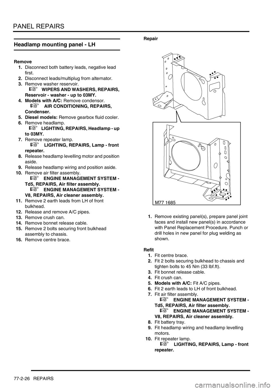
1.Remove existing panel(s), prepare panel joint
faces and install new panel(s) in accordance
with Panel Replacement Procedure. Punch or
drill holes in new panel for plug welding as
shown.
Refit
1.Fit centre brace.
2.Fit 2 bolts securing bulkhead to chassis and
tighten bolts to 45 Nm (33 lbf.ft).
3.Fit bonnet release cable.
4.Fit crush can.
5. Models with A/C: Fit A/C pipes.
6.Fit 2 earth leads to LH of front bulkhead.
7.Fit air filter assembly.
+ ENGINE MANAGEMENT SYSTEM -
Td5, REPAIRS, Air filter assembly.
+ ENGINE MANAGEMENT SYSTEM -
V8, REPAIRS, Air cleaner assembly.
8.Fit battery tray.
9.Fit headlamp wiring and headlamp levelling
motors.
10.Fit repeater lamp.
+ LIGHTING, REPAIRS, Lamp - front
repeater.
Page 1276 of 1672

PANEL REPAIRS
REPAIRS 77-2-27
11.Fit headlamp.
+ LIGHTING, REPAIRS, Headlamp - up
to 03MY.
12. Diesel models: Fit gearbox fluid cooler.
13. Models with A/C: Fit condensor.
+ AIR CONDITIONING, REPAIRS,
Condenser.
14.Fit washer reservoir.
+ WIPERS AND WASHERS, REPAIRS,
Reservoir - washer - up to 03MY.
15.Connect leads/multiplug to alternator.
16.Connect battery leads, negative lead last.
Valance upper assembly - LH
In this procedure, the front wing, the valance outer
reinforcement and the bonnet alarm switch mounting
bracket are replaced in conjunction with the LH
valance upper assembly.
Remove
1.Disconnect both battery leads, negative lead
first.
2.Disconnect leads/multiplug from alternator.
3.Remove front wing.
+ EXTERIOR FITTINGS, REPAIRS,
Wing - front - up to 03MY.
4.Remove air filter assembly.
+ ENGINE MANAGEMENT SYSTEM -
V8, REPAIRS, Air cleaner assembly.
+ ENGINE MANAGEMENT SYSTEM -
Td5, REPAIRS, Air filter assembly.
5.Remove PAS/ACE reservoir.
6.Remove ABS modulator.
+ BRAKES, REPAIRS, Modulator unit
- ABS.
7.Remove brake pipes from valance.
8.Release harness from valance and position
aside.
9. Models with A/C: Depressurise A/C system
and remove pipes from valance.
+ AIR CONDITIONING, REFRIGERANT
RECOVERY, RECYCLING AND
RECHARGING, Refrigerant recovery,
recycling and recharging.
Page 1304 of 1672

PANEL REPAIRS
TIMES 77-2-55
TIME S
TIME SCHEDULES
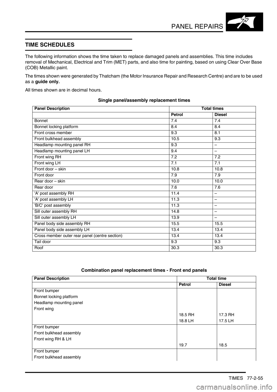
The following information shows the time taken to replace damaged panels and assemblies. This time includes
removal of Mechanical, Electrical and Trim (MET) parts, and also time for painting, based on using Clear Over Base
(COB) Metallic paint.
The times shown were generated by Thatcham (the Motor Insurance Repair and Research Centre) and are to be used
as a guide only.
All times shown are in decimal hours.
Single panel/assembly replacement times
Combination panel replacement times - Front end panels
Panel Description Total times
Petrol Diesel
Bonnet 7.4 7.4
Bonnet locking platform 8.4 8.4
Front cross member 9.3 8.1
Front bulkhead assembly 10.5 9.3
Headlamp mounting panel RH 9.3–
Headlamp mounting panel LH 9.4–
Front wing RH 7.2 7.2
Front wing LH 7.1 7.1
Front door – skin 10.8 10.8
Front door 7.9 7.9
Rear door – skin 10.0 10.0
Rear door 7.6 7.6
'A' post assembly RH 11.4–
'A' post assembly LH 11.3–
'B/C' post assembly 11.3–
Sill outer assembly RH 14.8–
Sill outer assembly LH 13.9–
Panel body side assembly RH 15.5 15.5
Panel body side assembly LH 13.4 13.4
Cross member outer rear panel (centre section) 13.4 13.4
Tail door 9.3 9.3
Roof 30.3 30.3
Panel DescriptionTotal time
Petrol Diesel
Front bumper
Bonnet locking platform
Headlamp mounting panel
Front wing
18.5 RH 17.3 RH
18.8 LH 17.5 LH
Front bumper
Front bulkhead assembly
Front wing RH & LH
19.7 18.5
Front bumper
Front bulkhead assembly
Page 1305 of 1672
PANEL REPAIRS
77-2-56 TIMES
Combination panel replacement times - Side panels
Front wing
Front valance assembly
Wing support bracket
Valance outer reinforcement
24.0 RH
24.2 LH 22.7
Front bumper
Front bulkhead assembly
Front wing
Wing support bracket
Headlamp closing panel
Valance upper assembly (front section)
Valance outer reinforcement (front section)
22.4 RH 21.1 RH
23.1 LH 21.6 LH
Panel DescriptionTotal time
Petrol Diesel
Front wing
Front door
11.2 11.2
Rear door
Panel bodyside assembly
19.2 RH 19.1 RH
17.1 LH 17.1 LH
Front door
Rear door
'B/C' Post
19.9 RH
19.8 LH 19.8
Front door
Rear door
'B/C' Post
Front wing
Panel bodyside assembly
33.9 RH 33.9 RH
31.8 LH 31.7 LH
Front door
Front wing
Front wing support bracket
'A' post
23.1 RH 23.0 RH
22.9 LH 22.8 RH Panel DescriptionTotal time
Petrol Diesel
Page 1341 of 1672

PAINTING
77-5-2 PROCEDURES
Paint preparation
Paint refinishing
The following process must be adhered to for paint refinishing operations.
1Seal required exterior and interior seams with an approved seam sealer
+ BODY SEALING MATERIALS, MATERIALS AND APPLICATIONS, Approved materials.
2Repair any damage to underbody sealers
+ CORROSION PREVENTION AND SEALING, CORROSION PREVENTION, Corrosion prevention.
3Apply a two-pack paint refinishing system
4Apply cavity wax to all interior surfaces which have not received refinish paint
Paint repairs
Before carrying out paintwork repairs, clean the vehicle thoroughly using either a steam cleaner or high-pressure
washer.
Wash locally repaired areas using a mild water-mixable detergent and wipe them clean with solvent, immediately
before paint application.
Ensure that damaged paintwork which has led to exposed metal is abraded until the metal is clean, extending beyond
the area of the original damage. Treat the bare metal with an etch phosphate to remove all traces of rust and to provide
a key for new paint coats. Re-treat the affected area using either a separate acid-etch primer and two-pack surfacer
or an integrated etch primer/filler, and follow with a two-pack paint system. Treat those surfaces not receiving paint
using an approved cavity wax, following paint operations.
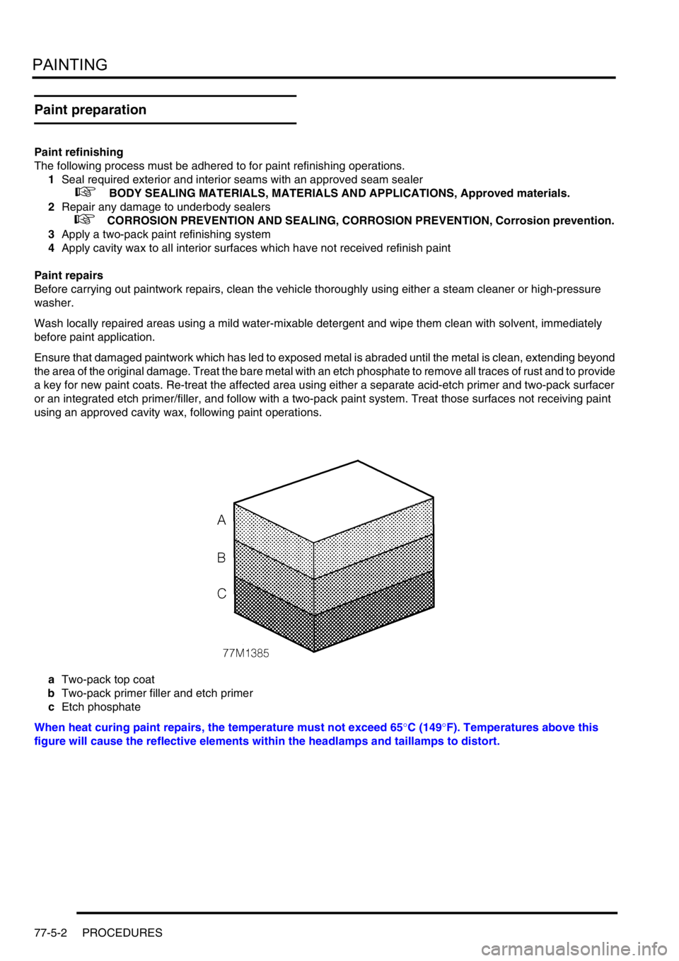
aTwo-pack top coat
bTwo-pack primer filler and etch primer
cEtch phosphate
When heat curing paint repairs, the temperature must not exceed 65
°C (149°F). Temperatures above this
figure will cause the reflective elements within the headlamps and taillamps to distort.
Page 1379 of 1672
AIR CONDITIONING
82-6DESCRIPTION AND OPERATION
Condenser
1Condenser matrix
2Outlet connection
3Inlet connection
The condenser transfers heat from the refrigerant to the surrounding air.
The condenser is installed immediately in front of the oil coolers. Rubber mounting bushes are used to mount the
condenser to the chassis sidemembers and brackets on the headlamp panels.
Ambient air, passing through the condenser matrix due to ram effect and/or the cooling fan, absorbs heat from the
refrigerant, which changes state from a vapour to a liquid.
Page 1422 of 1672
WIPERS AND WASHERS
DESCRIPTION AND OPERATION 84-1
WIPERS AND WASHERS DESCRIPTION AND OPERAT ION
Wipers and washers component layout
RHD shown, LHD similar
1Headlamp power wash relay
2Passenger compartment fuse box (rear wiper
relay, front wiper relay and IDM)
3Variable Delay Switch
4Front wash/ wipe switch
5Rear wiper motor
6Rear washer switch7Rear wiper switch
8Body Control Unit (BCU)
9Front washer pump
10Rear washer pump
11Front wiper motor assembly
12Headlamp power wash pump
Page 1425 of 1672
WIPERS AND WASHERS
84-4 DESCRIPTION AND OPERATION
Washer components
Reservoir with headlamp power wash shown