Page 970 of 1672
FRONT SUSPENSION
REPAIRS 60-31
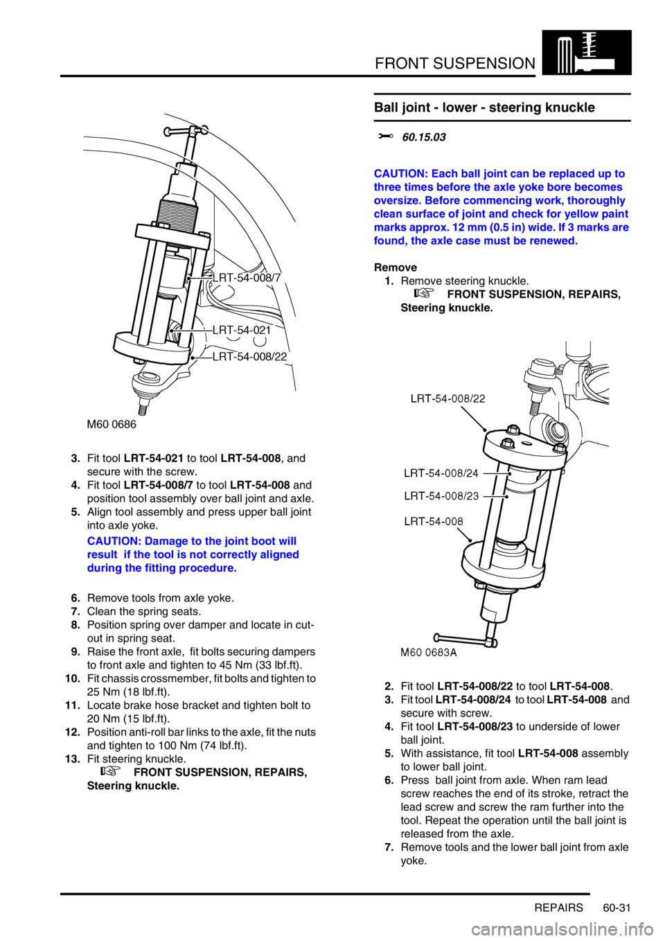
3.Fit tool LRT-54-021 to tool LRT-54-008, and
secure with the screw.
4.Fit tool LRT-54-008/7 to tool LRT-54-008 and
position tool assembly over ball joint and axle.
5.Align tool assembly and press upper ball joint
into axle yoke.
CAUTION: Damage to the joint boot will
result if the tool is not correctly aligned
during the fitting procedure.
6.Remove tools from axle yoke.
7.Clean the spring seats.
8.Position spring over damper and locate in cut-
out in spring seat.
9.Raise the front axle, fit bolts securing dampers
to front axle and tighten to 45 Nm (33 lbf.ft).
10.Fit chassis crossmember, fit bolts and tighten to
25 Nm (18 lbf.ft).
11.Locate brake hose bracket and tighten bolt to
20 Nm (15 lbf.ft).
12.Position anti-roll bar links to the axle, fit the nuts
and tighten to 100 Nm (74 lbf.ft).
13.Fit steering knuckle.
+ FRONT SUSPENSION, REPAIRS,
Steering knuckle.
Ball joint - lower - steering knuckle
$% 60.15.03
CAUTION: Each ball joint can be replaced up to
three times before the axle yoke bore becomes
oversize. Before commencing work, thoroughly
clean surface of joint and check for yellow paint
marks approx. 12 mm (0.5 in) wide. If 3 marks are
found, the axle case must be renewed.
Remove
1.Remove steering knuckle.
+ FRONT SUSPENSION, REPAIRS,
Steering knuckle.
2.Fit tool LRT-54-008/22 to tool LRT-54-008.
3.Fit tool LRT-54-008/24 to tool LRT-54-008 and
secure with screw.
4.Fit tool LRT-54-008/23 to underside of lower
ball joint.
5.With assistance, fit tool LRT-54-008 assembly
to lower ball joint.
6.Press ball joint from axle. When ram lead
screw reaches the end of its stroke, retract the
lead screw and screw the ram further into the
tool. Repeat the operation until the ball joint is
released from the axle.
7.Remove tools and the lower ball joint from axle
yoke.
Page 972 of 1672
FRONT SUSPENSION
REPAIRS 60-33
5.Remove 2 nuts securing ball joints to steering
knuckle.
6.Break taper joints using LRT-54-027 and
remove steering knuckle.
7.Remove tension collet from steering knuckle.
8.Remove drive shaft oil seal from axle casing.Refit
1.Clean taper bores in steering knuckle and
tension collet.
2.Fit tension collet into steering knuckle and
tighten to 5 Nm (3.7 lbf.ft).
3.Clean ball joint tapers and taper seats.
4.Position steering knuckle to axle yoke. Fit
upper ball joint nut and tighten to 110 Nm (81
lbf.ft). Fit lower ball joint nut and tighten to 135
Nm (100 lbf.ft).
5.Clean track rod and (if applicable) drag link
tapers and taper seats.
6.Connect track rod and drag link to steering
knuckle. Fit track rod and drag link nuts and
tighten to 80 Nm (59 lbf.ft).
7.Clean mudshield and steering knuckle mating
faces. Position mudshield, fit bolts and tighten
to 10 Nm (7 lbf.ft).
8.Fit wheel hub.
+ FRONT SUSPENSION, REPAIRS,
Wheel hub.
Page 973 of 1672

FRONT SUSPENSION
60-34 REPAIRS
Road spring - front
$% 60.20.11
Remove
1.Raise front of vehicle.
WARNING: Do not work on or under a
vehicle supported only by a jack. Always
support the vehicle on safety stands.
2.Support vehicle under chassis.
3.Remove front road wheels.
4.Support weight of front axle.
5.Remove 2 nuts securing anti-roll bar links to
front axle and disconnect links from axle.
6.Remove 2 bolts securing each damper to front
axle.
WARNING: Make sure the axle cannot move
when the damper is disconnected. The
damper limits the downward movement of
the axle. If the axle is not restrained,
disconnecting the damper will allow
unrestricted movement which may cause
personal injury or damage to equipment.
7.Lower front axle.
CAUTION: Ensure brake hoses and ABS
sensor harnesses are not damaged when
lowering front axle.
8.Release and remove front spring from damper.Refit
1.Clean front spring seats.
2.Position front spring, with close coil uppermost,
over damper and locate in cut out in lower
spring seat.
3.Ensure both front springs are correctly located
in spring seats and raise front axle. Fit bolts
securing both dampers to front axle and tighten
to 45 Nm (33 lbf.ft).
4.Ensure washer is in place on lower ball joint of
each anti-roll bar link, then connect lower ball
joints to axle. Tighten nuts to 100 Nm (74 lbf.ft).
5.Fit front road wheels and tighten nuts to 140
Nm (103 lbf.ft).
6.Remove stands and lower vehicle.
Page 1032 of 1672
REAR SUSPENSION
REPAIRS 64-27
Road spring - rear
$% 64.20.01
Remove
1.Raise rear of vehicle.
WARNING: Do not work on or under a
vehicle supported only by a jack. Always
support the vehicle on safety stands.
2.Support vehicle under chassis.
3.Remove road wheel.
4.Support weight of axle on a jack.
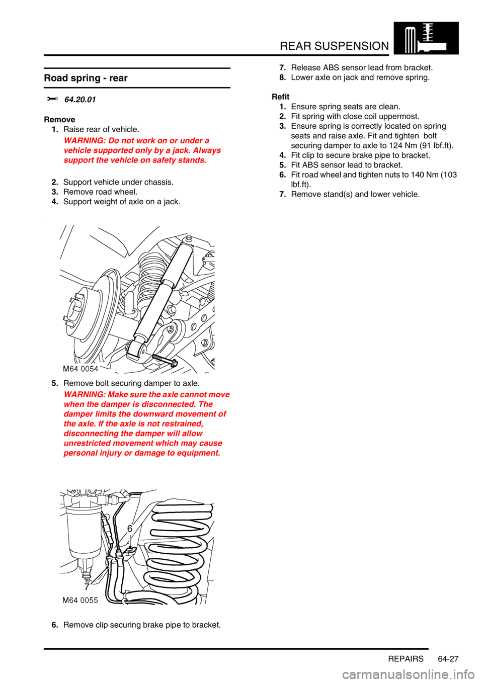
5.Remove bolt securing damper to axle.
WARNING: Make sure the axle cannot move
when the damper is disconnected. The
damper limits the downward movement of
the axle. If the axle is not restrained,
disconnecting the damper will allow
unrestricted movement which may cause
personal injury or damage to equipment.
6.Remove clip securing brake pipe to bracket. 7.Release ABS sensor lead from bracket.
8.Lower axle on jack and remove spring.
Refit
1.Ensure spring seats are clean.
2.Fit spring with close coil uppermost.
3.Ensure spring is correctly located on spring
seats and raise axle. Fit and tighten bolt
securing damper to axle to 124 Nm (91 lbf.ft).
4.Fit clip to secure brake pipe to bracket.
5.Fit ABS sensor lead to bracket.
6.Fit road wheel and tighten nuts to 140 Nm (103
lbf.ft).
7.Remove stand(s) and lower vehicle.
Page 1108 of 1672
RESTRAINT SYSTEMS
REPAIRS 75-13
REPAIRS
Seat belt - front
$% 76.73.13
Remove
1.Remove 'B' post lower trim casing.
+ INTERIOR TRIM COMPONENTS,
REPAIRS, Trim casing - lower - 'B' post.
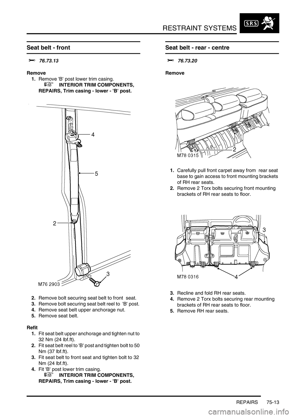
2.Remove bolt securing seat belt to front seat.
3.Remove bolt securing seat belt reel to 'B' post.
4.Remove seat belt upper anchorage nut.
5.Remove seat belt.
Refit
1.Fit seat belt upper anchorage and tighten nut to
32 Nm (24 lbf.ft).
2.Fit seat belt reel to 'B' post and tighten bolt to 50
Nm (37 lbf.ft).
3.Fit seat belt to front seat and tighten bolt to 32
Nm (24 lbf.ft).
4.Fit 'B' post lower trim casing.
+ INTERIOR TRIM COMPONENTS,
REPAIRS, Trim casing - lower - 'B' post.
Seat belt - rear - centre
$% 76.73.20
Remove
1.Carefully pull front carpet away from rear seat
base to gain access to front mounting brackets
of RH rear seats.
2.Remove 2 Torx bolts securing front mounting
brackets of RH rear seats to floor.
3.Recline and fold RH rear seats.
4.Remove 2 Torx bolts securing rear mounting
brackets of RH rear seats to floor.
5.Remove RH rear seats.
Page 1109 of 1672
RESTRAINT SYSTEMS
75-14 REPAIRS
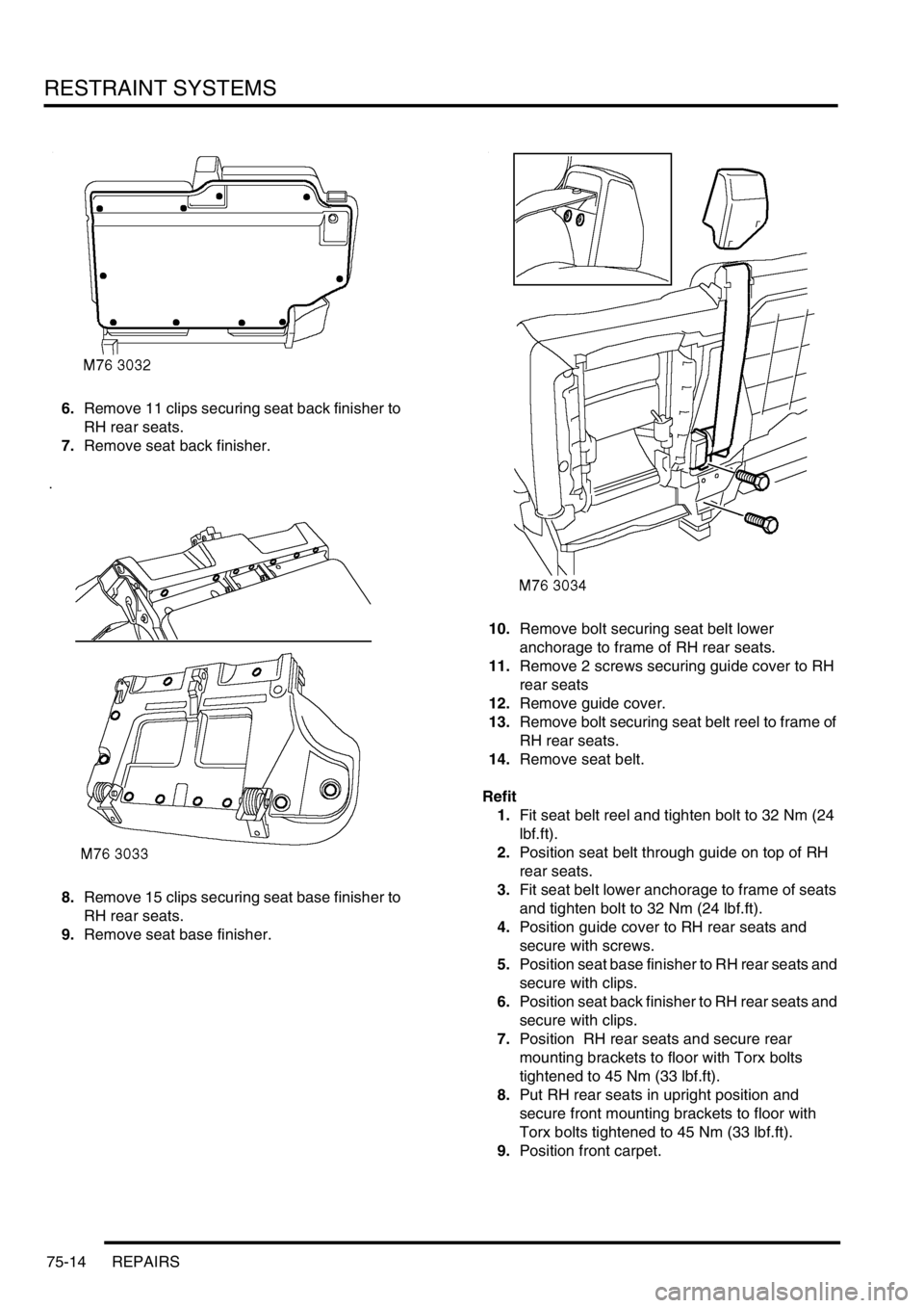
6.Remove 11 clips securing seat back finisher to
RH rear seats.
7.Remove seat back finisher.
8.Remove 15 clips securing seat base finisher to
RH rear seats.
9.Remove seat base finisher. 10.Remove bolt securing seat belt lower
anchorage to frame of RH rear seats.
11.Remove 2 screws securing guide cover to RH
rear seats
12.Remove guide cover.
13.Remove bolt securing seat belt reel to frame of
RH rear seats.
14.Remove seat belt.
Refit
1.Fit seat belt reel and tighten bolt to 32 Nm (24
lbf.ft).
2.Position seat belt through guide on top of RH
rear seats.
3.Fit seat belt lower anchorage to frame of seats
and tighten bolt to 32 Nm (24 lbf.ft).
4.Position guide cover to RH rear seats and
secure with screws.
5.Position seat base finisher to RH rear seats and
secure with clips.
6.Position seat back finisher to RH rear seats and
secure with clips.
7.Position RH rear seats and secure rear
mounting brackets to floor with Torx bolts
tightened to 45 Nm (33 lbf.ft).
8.Put RH rear seats in upright position and
secure front mounting brackets to floor with
Torx bolts tightened to 45 Nm (33 lbf.ft).
9.Position front carpet.
Page 1113 of 1672
RESTRAINT SYSTEMS
75-18 REPAIRS
Pre-tensioner - front seat belt
$% 76.73.30
WARNING: It is imperative that before any work
is undertaken on the SRS system the appropriate
information is read thoroughly.
WARNING: Always disconnect both battery leads
before beginning work on the SRS system.
Disconnect the negative battery lead first. Never
reverse connect the battery.
Remove
1.Remove the key from the starter switch.
Disconnect both battery leads, negative lead
first. Wait ten minutes before starting work.
2.Remove front seat.
+ SEATS, REPAIRS, Seat - front.
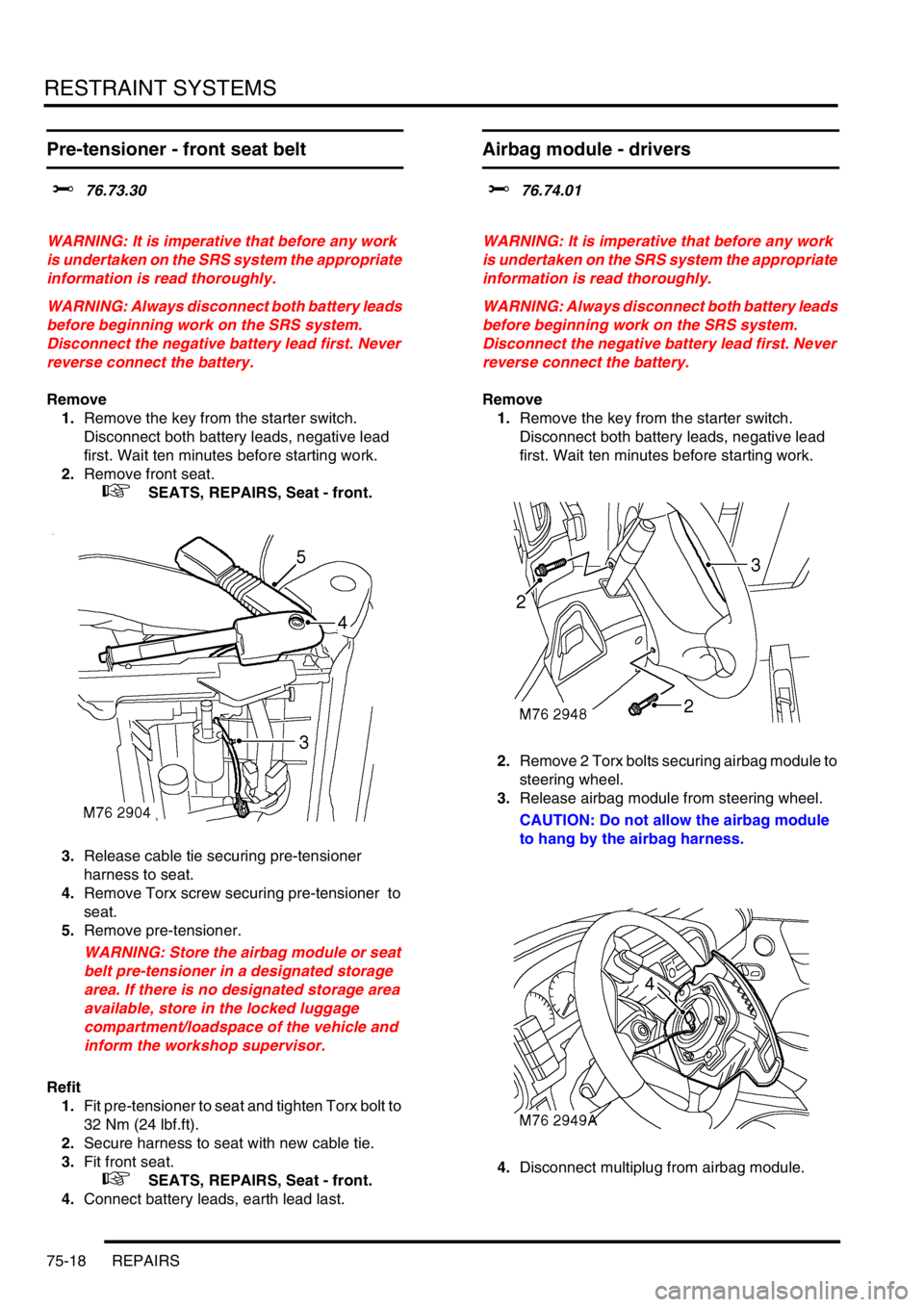
3.Release cable tie securing pre-tensioner
harness to seat.
4.Remove Torx screw securing pre-tensioner to
seat.
5.Remove pre-tensioner.
WARNING: Store the airbag module or seat
belt pre-tensioner in a designated storage
area. If there is no designated storage area
available, store in the locked luggage
compartment/loadspace of the vehicle and
inform the workshop supervisor.
Refit
1.Fit pre-tensioner to seat and tighten Torx bolt to
32 Nm (24 lbf.ft).
2.Secure harness to seat with new cable tie.
3.Fit front seat.
+ SEATS, REPAIRS, Seat - front.
4.Connect battery leads, earth lead last.
Airbag module - drivers
$% 76.74.01
WARNING: It is imperative that before any work
is undertaken on the SRS system the appropriate
information is read thoroughly.
WARNING: Always disconnect both battery leads
before beginning work on the SRS system.
Disconnect the negative battery lead first. Never
reverse connect the battery.
Remove
1.Remove the key from the starter switch.
Disconnect both battery leads, negative lead
first. Wait ten minutes before starting work.
2.Remove 2 Torx bolts securing airbag module to
steering wheel.
3.Release airbag module from steering wheel.
CAUTION: Do not allow the airbag module
to hang by the airbag harness.
4.Disconnect multiplug from airbag module.
Page 1154 of 1672
INTERIOR TRIM COMPONENTS
REPAIRS 76-3-1
INTERIOR TRIM COMPONENTS REPAIRS
Trim casing - tail door speaker
$% 76.13.11
Remove
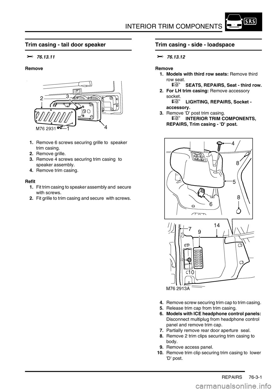
1.Remove 6 screws securing grille to speaker
trim casing.
2.Remove grille.
3.Remove 4 screws securing trim casing to
speaker assembly.
4.Remove trim casing.
Refit
1.Fit trim casing to speaker assembly and secure
with screws.
2.Fit grille to trim casing and secure with screws.
Trim casing - side - loadspace
$% 76.13.12
Remove
1. Models with third row seats: Remove third
row seat.
+ SEATS, REPAIRS, Seat - third row.
2. For LH trim casing: Remove accessory
socket.
+ LIGHTING, REPAIRS, Socket -
accessory.
3.Remove 'D' post trim casing.
+ INTERIOR TRIM COMPONENTS,
REPAIRS, Trim casing - 'D' post.
4.Remove screw securing trim cap to trim casing.
5.Release trim cap from trim casing.
6. Models with ICE headphone control panels:
Disconnect multiplug from headphone control
panel and remove trim cap.
7.Partially remove rear door aperture seal.
8.Remove 2 trim clips securing trim casing to
body.
9.Remove access panel.
10.Remove trim clip securing trim casing to lower
'D' post.