2002 LAND ROVER DISCOVERY remove seats
[x] Cancel search: remove seatsPage 1299 of 1672
PANEL REPAIRS
77-2-50 REPAIRS
Rear floor complete assembly
Remove
1.Disconnect both battery leads, negative lead
first.
2.Disconnect leads/multiplug from alternator.
3.Remove loadspace carpet.
+ INTERIOR TRIM COMPONENTS,
REPAIRS, Carpet - loadspace.
4.Remove rear seats.
+ SEATS, REPAIRS, Seat - rear.
5.Remove rear carpet.
+ INTERIOR TRIM COMPONENTS,
REPAIRS, Carpet - rear.
6.Remove rear bumper assembly.
+ EXTERIOR FITTINGS, REPAIRS,
Bumper assembly - rear - up to 03MY.
7.Remove RH and LH mud flap and brackets.
8.Remove exhaust tail pipe heatshields.
9.Remove tread plates from rear door apertures.
10.Remove rear door aperture seal.
11.Remove tail door tread plate.
12.Remove loadspace carpet retainer.
13.Remove head lining rear trim finisher.
14.Remove tail door aperture seal.
15.Remove bolts securing body to chassis.
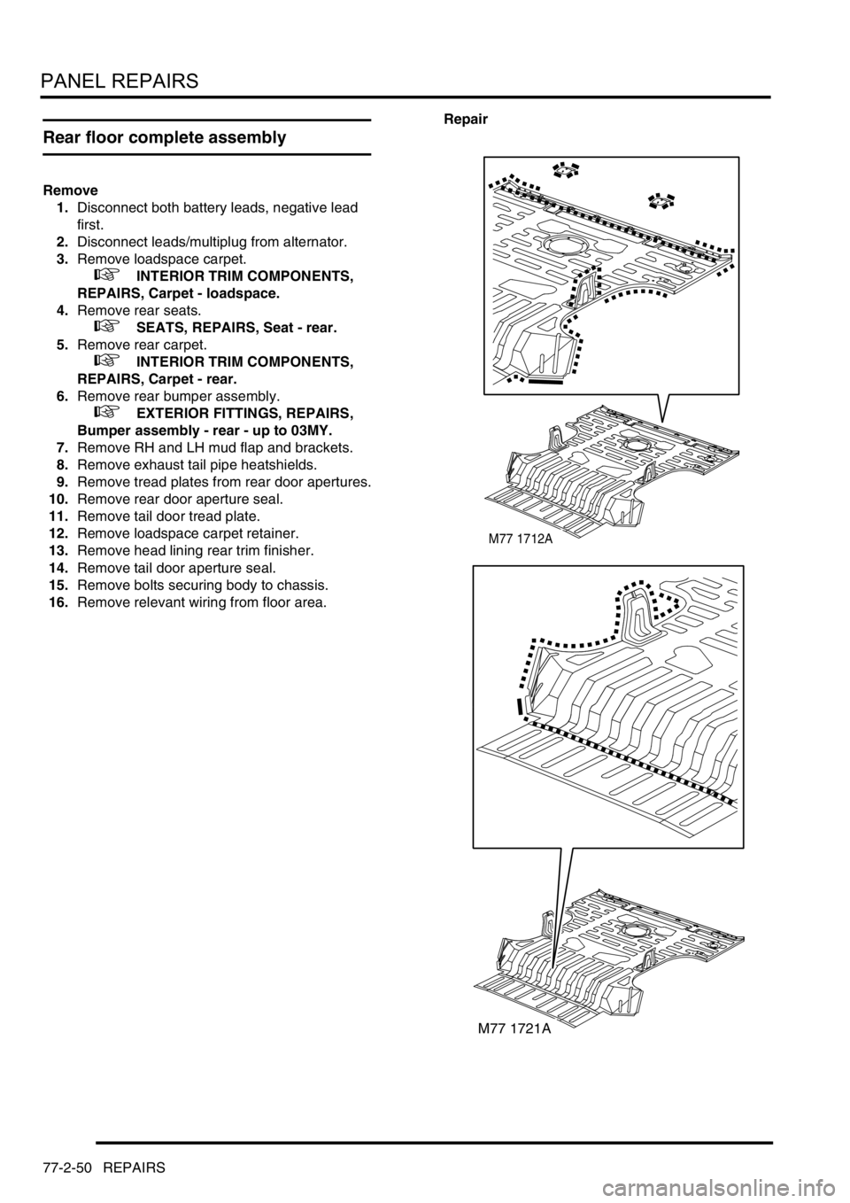
16.Remove relevant wiring from floor area.Repair
M77 1712A
M77 1721A
Page 1300 of 1672
PANEL REPAIRS
REPAIRS 77-2-51
1.Remove existing panel(s), prepare panel joint
faces and install new panel(s) in accordance
with Panel Replacement Procedure. Punch or
drill holes in new panel for plug welding as
shown.
Refit
1.Position and secure wiring.
2.Fit and tighten bolts securing body to chassis to
45 Nm (33 lbf.ft).
3.Fit tail door aperture seal.
4.Fit head lining rear trim finisher.
5.Fit loadspace carpet retainer.
6.Fit tail door tread plate.
7.Fit rear door aperture seals.
8.Fit tread plate to rear door apertures.
9.Fit exhaust tail pipe heatshields.
10.Fit mud flap bracklets and mud flaps.
11.Fit rear bumper assembly.
+ EXTERIOR FITTINGS, REPAIRS,
Bumper assembly - rear - up to 03MY.
12.Fit rear carpet.
+ INTERIOR TRIM COMPONENTS,
REPAIRS, Carpet - rear.
13.Fit rear seats.
+ SEATS, REPAIRS, Seat - rear.
14.Fit loadspace carpet.
+ INTERIOR TRIM COMPONENTS,
REPAIRS, Carpet - loadspace.
15.Connect leads/multiplug to alternator.
16.Connect battery leads, negative lead last.
Rear floor (rear section)
In this procedure, the cross member rear assembly,
cross member outer rear panel, cross member
closing rear panel, 'E' post assembly, 'E' post closing
assembly and the panel body side assembly are
replaced in conjunction with the rear floor (rear
section).
Remove
1.Disconnect both battery leads, negative lead
first.
2.Disconnect leads/multiplug from alternator.
3.Remove cross member rear assembly.
+ PANEL REPAIRS, REPAIRS, Cross
member rear assembly.
4.Remove mud flap mounting brackets.
5. LH side: Remove exhaust heatshield from rear
floor.
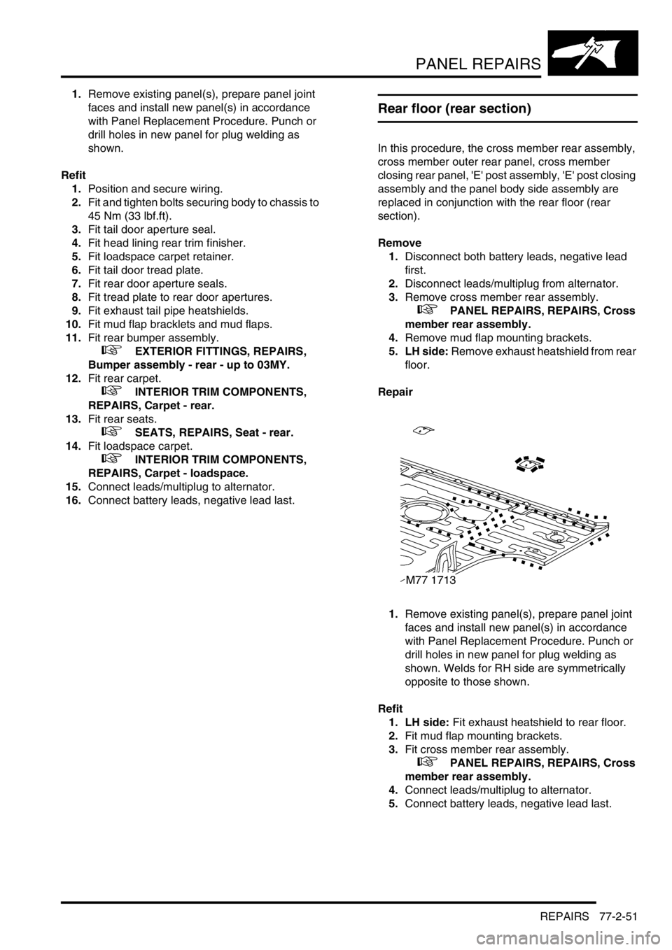
Repair
1.Remove existing panel(s), prepare panel joint
faces and install new panel(s) in accordance
with Panel Replacement Procedure. Punch or
drill holes in new panel for plug welding as
shown. Welds for RH side are symmetrically
opposite to those shown.
Refit
1. LH side: Fit exhaust heatshield to rear floor.
2.Fit mud flap mounting brackets.
3.Fit cross member rear assembly.
+ PANEL REPAIRS, REPAIRS, Cross
member rear assembly.
4.Connect leads/multiplug to alternator.
5.Connect battery leads, negative lead last.
Page 1301 of 1672
PANEL REPAIRS
77-2-52 REPAIRS
Rear floor (RH/LH section)
In this procedure, the cross member rear assembly,
cross member outer rear panel (RH/LH section),
cross member closing rear panel, 'E' post assembly,
'E' post closing assembly and the panel body side
assembly are replaced in conjunction with the rear
floor (RH/LH section).
Remove
1.Disconnect both battery leads, negative lead
first.
2.Disconnect leads/multiplug from alternator.
3.Remove cross member rear assembly.
+ PANEL REPAIRS, REPAIRS, Cross
member rear assembly.
4.Remove mud flap mounting brackets.
5. LH side: Remove exhaust heatshield from rear
floor.
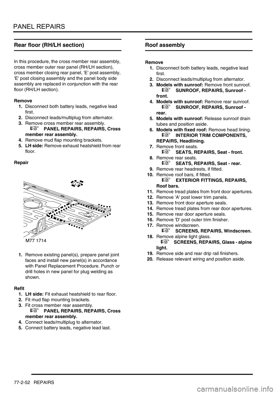
Repair
1.Remove existing panel(s), prepare panel joint
faces and install new panel(s) in accordance
with Panel Replacement Procedure. Punch or
drill holes in new panel for plug welding as
shown.
Refit
1. LH side: Fit exhaust heatshield to rear floor.
2.Fit mud flap mounting brackets.
3.Fit cross member rear assembly.
+ PANEL REPAIRS, REPAIRS, Cross
member rear assembly.
4.Connect leads/multiplug to alternator.
5.Connect battery leads, negative lead last.
Roof assembly
Remove
1.Disconnect both battery leads, negative lead
first.
2.Disconnect leads/multiplug from alternator.
3. Models with sunroof: Remove front sunroof.
+ SUNROOF, REPAIRS, Sunroof -
front.
4. Models with sunroof: Remove rear sunroof.
+ SUNROOF, REPAIRS, Sunroof -
rear.
5. Models with sunroof: Release sunroof drain
tubes and position aside.
6. Models with fixed roof: Remove head lining.
+ INTERIOR TRIM COMPONENTS,
REPAIRS, Headlining.
7.Remove front seats.
+ SEATS, REPAIRS, Seat - front.
8.Remove rear seats.
+ SEATS, REPAIRS, Seat - rear.
9.Remove rear headrests, if fitted.
10.Remove roof bars, if fitted.
+ EXTERIOR FITTINGS, REPAIRS,
Roof bars.
11.Remove tread plates from front door apertures.
12.Remove 'A' post lower trim panels.
13.Remove front door aperture seals.
14.Remove tread plates from rear door apertures.
15.Remove rear door aperture seals.
16.Remove 'D' post outer trim finisher.
17.Remove windscreen.
+ SCREENS, REPAIRS, Windscreen.
18.Remove alpine light glass.
+ SCREENS, REPAIRS, Glass - alpine
light.
19.Remove side and rear drip rail finishers.
20.Release relevant wiring and position aside.
Page 1302 of 1672
PANEL REPAIRS
REPAIRS 77-2-53
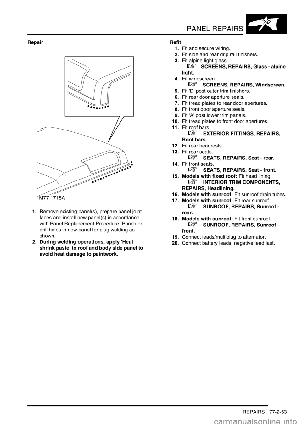
Repair
1.Remove existing panel(s), prepare panel joint
faces and install new panel(s) in accordance
with Panel Replacement Procedure. Punch or
drill holes in new panel for plug welding as
shown.
2. During welding operations, apply 'Heat
shrink paste' to roof and body side panel to
avoid heat damage to paintwork.Refit
1.Fit and secure wiring.
2.Fit side and rear drip rail finishers.
3.Fit alpine light glass.
+ SCREENS, REPAIRS, Glass - alpine
light.
4.Fit windscreen.
+ SCREENS, REPAIRS, Windscreen.
5.Fit 'D' post outer trim finishers.
6.Fit rear door aperture seals.
7.Fit tread plates to rear door apertures.
8.Fit front door aperture seals.
9.Fit 'A' post lower trim panels.
10.Fit tread plates to front door apertures.
11.Fit roof bars.
+ EXTERIOR FITTINGS, REPAIRS,
Roof bars.
12.Fit rear headrests.
13.Fit rear seats.
+ SEATS, REPAIRS, Seat - rear.
14.Fit front seats.
+ SEATS, REPAIRS, Seat - front.
15. Models with fixed roof: Fit head lining.
+ INTERIOR TRIM COMPONENTS,
REPAIRS, Headlining.
16. Models with sunroof: Fit sunroof drain tubes.
17. Models with sunroof: Fit rear sunroof.
+ SUNROOF, REPAIRS, Sunroof -
rear.
18. Models with sunroof: Fit front sunroof.
+ SUNROOF, REPAIRS, Sunroof -
front.
19.Connect leads/multiplug to alternator.
20.Connect battery leads, negative lead last.
M77 1715A
Page 1557 of 1672
IN CAR ENTERTAINMENT
86-6-4 DESCRIPTION AND OPERATION
Description
General
The in car entertainment (ICE) system allows the driver and passengers to listen to audio output from the speakers
or optional headphones inside the vehicle. Buttons or knobs on the radio cassette allow changes of levels or
selections during the various modes of operation. The system can be controlled from the fascia mounted radio
cassette, or optional remote control switches on the left hand side of the steering wheel. High line systems may also
have rear headphone amplifiers that have some control of the system via the radio cassette player.
One or two amplified aerials located in the rear side windows send radio signals to the radio cassette player. On high
line systems a power amplifier and a CD-autochanger may be located under the front seats. Speakers are located in
the lower door panels, additional speakers may be located in upper door trim, the A-post and the tail door. A display
screen shows the user the current system status.
The ICE supplied varies with trim level and market. Vehicles may not have all of the speakers, amplified aerials, CD-
autochanger, rear headphone amplifiers or power amplifier.
Base system radio cassette
The base radio cassette has buttons for LD (loudness) AM, FM, EJECT (tape), Reverse, Base/Balance, treble, MAN
forward and reverse. The base radio cassette is located in the center of the fascia and contains the radio and tape
player, four clips (accessible through holes in the front of the unit) secure the unit in the fascia. To remove the unit
the four clips must be released with a special tool. The base system can be controlled from the fascia mounted radio
cassette. A logic control circuit in the radio cassette player controls the operation in the various control modes.
The radio cassette has a display screen, the information shown can be the current radio frequency, tape operating,
bass or loudness settings. Power for the illumination on the radio cassette is supplied from the passenger
compartment fuse box. A main fuse is also located in the connector socket area on the back of the radio cassette.
Security code function
A combination of buttons on the radio cassette are used to input and change security codes. Security codes make the
unit unusable if the unit is disconnected from the vehicle without deactivating the security code. The radio cassette
has an internal memory chip that stores the code information, if the power is removed from the unit the chip will
activate the security code feature. For this reason the security code feature must be deactivated before the unit is
removed or the vehicles battery is disconnected.
Audio functions
The radio cassette has buttons for the following audio functions: LD (loudness), bass/balance, fader, treble and
volume.
Cassette functions
The radio cassette has buttons for the following cassette functions: eject, forward, reverse and tape reversal.
Multi function buttons
The function of presets 1-6 and the MAN button depends on current mode of operation and allows selection of radio
band, radio on, tape track and search/seek functions. The MAN button is mode dependent, when pressed the button
allows manual operation or alternate mode selections such as manual tuning.
Internal memory
An internal memory chip stores the station presets and security code, power is supplied internally to the chip via a
permanent power feed, supplied from the passenger compartment fuse box.
Page 1571 of 1672
IN CAR ENTERTAINMENT
86-6-18 REPAIRS
Speaker - tail door
$% 86.50.42
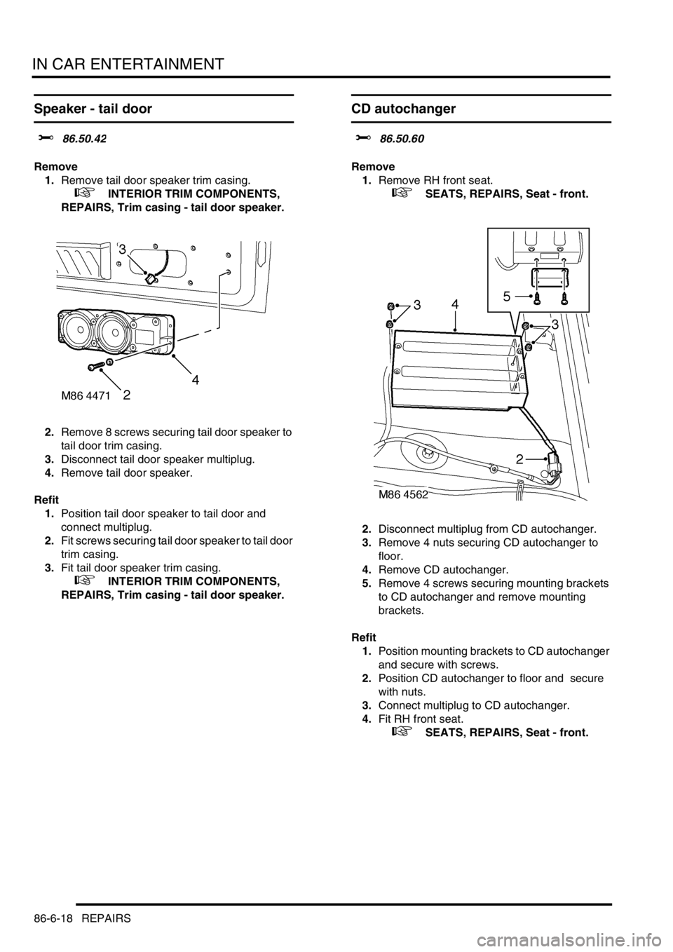
Remove
1.Remove tail door speaker trim casing.
+ INTERIOR TRIM COMPONENTS,
REPAIRS, Trim casing - tail door speaker.
2.Remove 8 screws securing tail door speaker to
tail door trim casing.
3.Disconnect tail door speaker multiplug.
4.Remove tail door speaker.
Refit
1.Position tail door speaker to tail door and
connect multiplug.
2.Fit screws securing tail door speaker to tail door
trim casing.
3.Fit tail door speaker trim casing.
+ INTERIOR TRIM COMPONENTS,
REPAIRS, Trim casing - tail door speaker.
CD autochanger
$% 86.50.60
Remove
1.Remove RH front seat.
+ SEATS, REPAIRS, Seat - front.
2.Disconnect multiplug from CD autochanger.
3.Remove 4 nuts securing CD autochanger to
floor.
4.Remove CD autochanger.
5.Remove 4 screws securing mounting brackets
to CD autochanger and remove mounting
brackets.
Refit
1.Position mounting brackets to CD autochanger
and secure with screws.
2.Position CD autochanger to floor and secure
with nuts.
3.Connect multiplug to CD autochanger.
4.Fit RH front seat.
+ SEATS, REPAIRS, Seat - front.