2002 LAND ROVER DISCOVERY heater
[x] Cancel search: heaterPage 1393 of 1672

AIR CONDITIONING
82-20DESCRIPTION AND OPERATION
Air distribution control
To control the air distribution within the cabin the ATC ECU signals the servo motor controlling the distribution flaps
in the heater assembly to move to the flaps to the appropriate position.
In the automatic and economy modes, if the LH or RH temperature selections are set to LO or HI, air distribution is
fixed as follows:
lIf one is set to LO and one is set to a specific temperature, to face level only.
lIf one is set to HI and one is set to a specific temperature, to footwells only.
lIf one is set to LO and one is set to HI, to face level and footwells.
When specific LH and RH temperature selections are set, air distribution is determined from the target air outlet
temperatures. For higher target air outlet temperatures, air distribution is set to footwells only. For lower target air
outlet temperatures, air distribution is set to face level only. For intermediate target air outlet temperatures, air
distribution is set to face level and footwells. When the air distribution is set to face level and footwells, the ATC ECU
varies the bias between the footwells and the face level outlets, in three stages, to provide a gradual transition of air
distribution from footwells only to face level only. The three stages of bias are also employed when the air distribution
is manually selected to face level and footwells.
During warm-up, the air distribution changes to face level and footwells for a period, then reverts to footwells only.
The period of air distribution at face level and footwells can be cancelled by pressing and holding the on/off and defrost
mode switches, then turning the ignition switch from off to on. Pressing and holding the AUTO and defrost switches,
then turning the ignition switch from off to on, restores the period of air distribution at face level and footwells.
Compressor control
To engage the compressor clutch, the ATC ECU outputs a compressor clutch request to the ECM, which then
energises the A/C compressor clutch relay. Compressor operation is governed by the evaporator outlet air
temperature, at one of two settings, dependent on the amount of cooling required. When more cooling is required, the
compressor clutch request is output if evaporator outlet air temperature increases to 4
°C (39 °F) and cancelled when
it decreases to 3
°C (37 °F). When less cooling is required, the compressor clutch request is output if evaporator outlet
air temperature increases to 11
°C (52 °F) and cancelled when it decreases to 10 °C (50 °F).
Engine cooling fan control
While the A/C system is on, operation of the electric engine cooling fan, to assist refrigerant condenser operation, is
determined by a combination of vehicle speed and external air temperature. When cooling fan operation is required,
the ATC ECU outputs a cooling fan request to the ECM, which then energises the cooling fan relay. The cooling fan
request is output if vehicle speed is 80 km/h or less while the external air temperature is 28
°C (82 °F) or more. The
request is cancelled, and the cooling fan switched off, if either the vehicle speed increases to 100 km/h, or the external
air temperature decreases to 25
°C (77 °F).
Default settings
If the battery power supply to the ATC ECU is disrupted for any reason, e.g. battery disconnected, the system reverts
to default settings when the battery power supply is restored. Default settings are:
lTemperature indications in
°C (in some markets a conversion connector is fitted to the ATC ECU to change the
default temperature scale to
°F).
lLH and RH outlet temperatures of 22
°C (72 °F).
laudible warning switched on.
lWarm-up air distribution (to face level and footwells) function switched on.
lIf the system is first switched on using the A/C on/off switch, the automatic mode is engaged, regardless of the
settings in use when the battery was disconnected.
Page 1394 of 1672

AIR CONDITIONING
DESCRIPTION AND OPERATION 82-21
Diagnostics
The ATC ECU performs a diagnostic check each time the ignition is switched on. To avoid nuisance fault indications
at low light levels, the sunlight sensor is omitted from the diagnostic check. If a fault is detected, the audible warning
sounds three times and the AUTO window on the control panel display flashes for 20 seconds. The ATC ECU then
reverts to normal control but uses a default value or strategy for the detected fault. Faults are identified by performing
a manual diagnostic check of the system.
A manual diagnostic check includes a check of the sunlight sensor, and is initiated by pressing and holding the AUTO
switch and the air distribution switch, then turning the ignition switch from off to on. The audible warning sounds once
and the indications on the control panel display illuminate. FC is shown in the LH temperature window and the results
of the check are shown as a two digit fault code in the RH temperature window. If a fault is detected, the audible
warning sounds three times and the AUTO window on the display flashes on and off for 20 seconds. If more than one
fault is detected, the fault codes cycle in numerical order, at 1 Hz. The audible warning sounds as each fault code is
shown. In low light conditions, to avoid false sunlight sensor fault indications, the sunlight sensor should be illuminated
with a strong light source.
Diagnostic fault codes and fault descriptions
Code Component Fault Default value/strategy
00 - No fault found -
11 In-car temperature sensor Open or short circuit 25°C (77°F)
12 Ambient temperature sensor Open or short circuit 10°C (50°F)
Cooling fan permanently on
Display shows "- -" if external
air temperature selected
13 Thermistor Open or short circuit 0°C (32°F)
14 Heater coolant temperature sensor Open or short circuit 70°C (158°F)
21 Sunlight sensor, left output Open or short circuit No solar heating correction
22 Sunlight sensor, right output Open or short circuit No solar heating correction
31 LH temperature servo motor Open or short circuit
Motor or flap mechanism seizedServo motor locked in position
32 RH temperature servo motor Open or short circuit
Motor or flap mechanism seizedServo motor locked in position
33 Distribution servo motor Open or short circuit
Motor or flap mechanism seizedServo motor locked in position
Page 1404 of 1672
AIR CONDITIONING
REPAIRS 82-31
REPAIRS
Compressor - diesel
$% 82.10.20
Remove
1.Remove engine acoustic cover.
2.Depressurise air conditioning system.
+ AIR CONDITIONING, REFRIGERANT
RECOVERY, RECYCLING AND
RECHARGING, Refrigerant recovery,
recycling and recharging.
3.Remove auxiliary drive belt.
+ CHARGING AND STARTING,
REPAIRS, Belt - auxiliary drive.
4.Drain cooling system.
+ COOLING SYSTEM - Td5,
ADJUSTMENTS, Drain and refill.
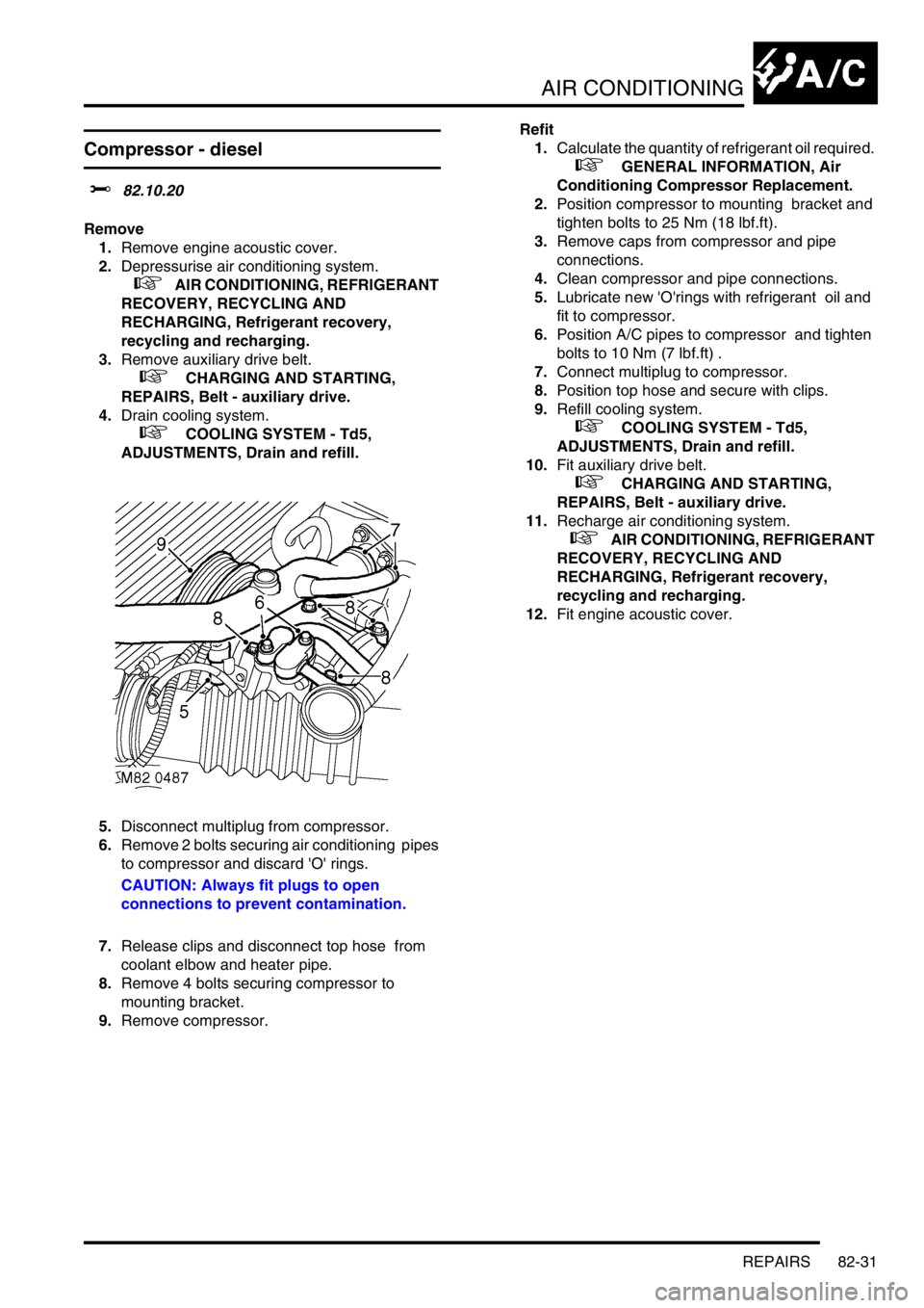
5.Disconnect multiplug from compressor.
6.Remove 2 bolts securing air conditioning pipes
to compressor and discard 'O' rings.
CAUTION: Always fit plugs to open
connections to prevent contamination.
7.Release clips and disconnect top hose from
coolant elbow and heater pipe.
8.Remove 4 bolts securing compressor to
mounting bracket.
9.Remove compressor.Refit
1.Calculate the quantity of refrigerant oil required.
+ GENERAL INFORMATION, Air
Conditioning Compressor Replacement.
2.Position compressor to mounting bracket and
tighten bolts to 25 Nm (18 lbf.ft).
3.Remove caps from compressor and pipe
connections.
4.Clean compressor and pipe connections.
5.Lubricate new 'O'rings with refrigerant oil and
fit to compressor.
6.Position A/C pipes to compressor and tighten
bolts to 10 Nm (7 lbf.ft) .
7.Connect multiplug to compressor.
8.Position top hose and secure with clips.
9.Refill cooling system.
+ COOLING SYSTEM - Td5,
ADJUSTMENTS, Drain and refill.
10.Fit auxiliary drive belt.
+ CHARGING AND STARTING,
REPAIRS, Belt - auxiliary drive.
11.Recharge air conditioning system.
+ AIR CONDITIONING, REFRIGERANT
RECOVERY, RECYCLING AND
RECHARGING, Refrigerant recovery,
recycling and recharging.
12.Fit engine acoustic cover.
Page 1413 of 1672
AIR CONDITIONING
82-40REPAIRS
Evaporator, evaporator thermistor and
thermal expansion valve (TXV)
$% 82.25.20
Remove
1.Remove heater assembly.
+ HEATING AND VENTILATION,
REPAIRS, Heater assembly - models with
air conditioning.
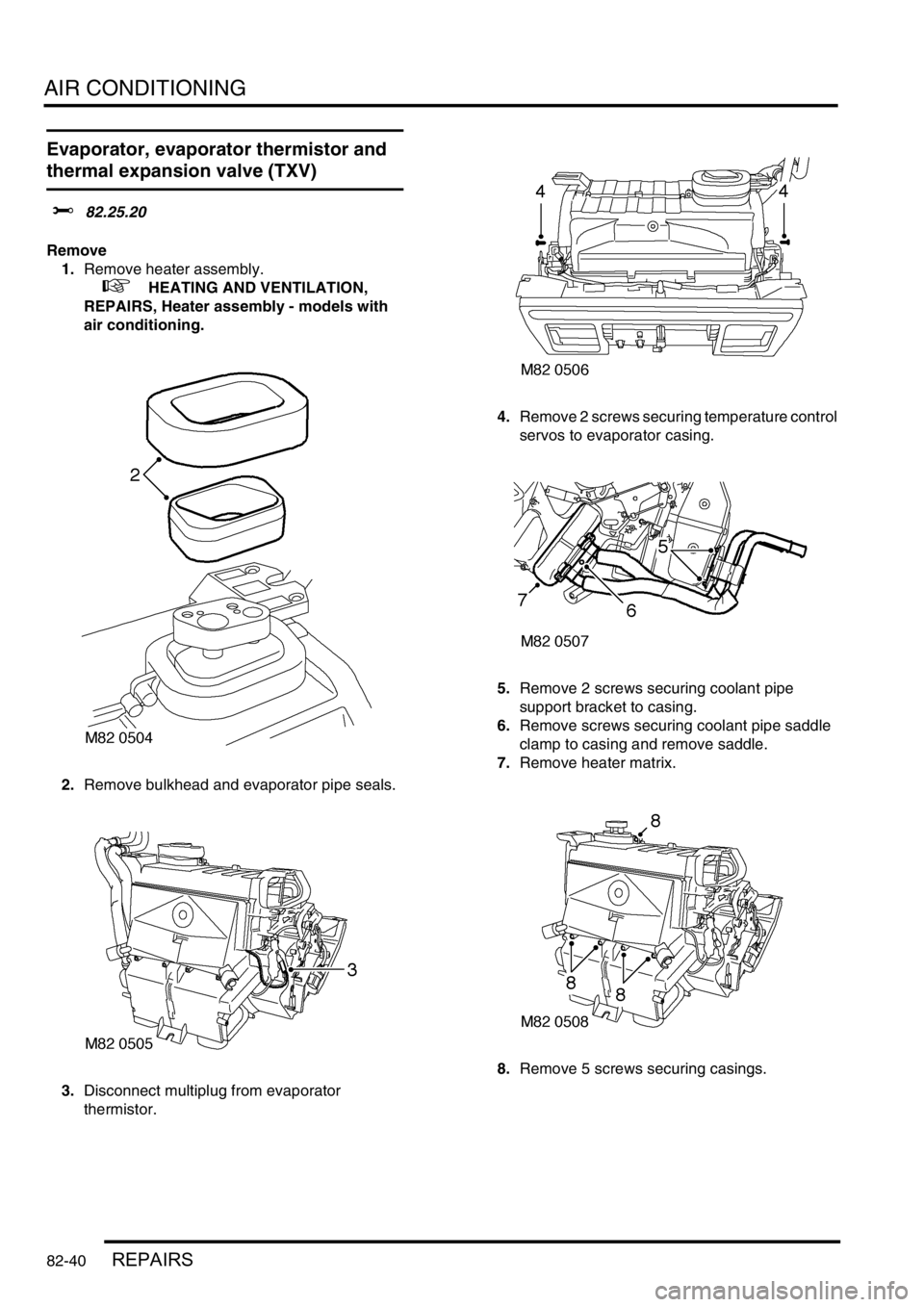
2.Remove bulkhead and evaporator pipe seals.
3.Disconnect multiplug from evaporator
thermistor. 4.Remove 2 screws securing temperature control
servos to evaporator casing.
5.Remove 2 screws securing coolant pipe
support bracket to casing.
6.Remove screws securing coolant pipe saddle
clamp to casing and remove saddle.
7.Remove heater matrix.
8.Remove 5 screws securing casings.
Page 1415 of 1672
AIR CONDITIONING
82-42REPAIRS
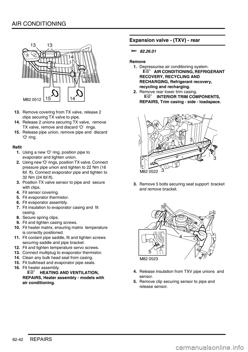
13.Remove covering from TX valve, release 2
clips securing TX valve to pipe.
14.Release 2 unions securing TX valve, remove
TX valve, remove and discard 'O' rings.
15.Release pipe union, remove pipe and discard
'O' ring.
Refit
1.Using a new 'O' ring, position pipe to
evaporator and tighten union.
2.Using new 'O' rings, position TX valve. Connect
pressure pipe union and tighten to 22 Nm (16
lbf. ft). Connect evaporator pipe and tighten to
32 Nm (24 lbf.ft).
3.Position TX valve sensor to pipe and secure
with clips.
4.Fit sensor covering.
5.Fit evaporator thermistor.
6.Fit evaporator assembly.
7.Fit insulation to evaporator casing and fit
casing.
8.Secure spring clips.
9.Fit and tighten casing screws.
10.Fit heater matrix, ensuring matrix temperature
is correctly positioned.
11.Fit coolant pipe saddle, fit and tighten screws
securing saddle and pipe bracket.
12.Fit and tighten temperature servo screws.
13.Connect multiplug to evaporator thermistor.
14.Clean any bulk head seal from casing.
15.Fit bulkhead and evaporator pipe seals.
16.Fit heater assembly.
+ HEATING AND VENTILATION,
REPAIRS, Heater assembly - models with
air conditioning.
Expansion valve - (TXV) - rear
$% 82.26.01
Remove
1.Depressurise air conditioning system.
+ AIR CONDITIONING, REFRIGERANT
RECOVERY, RECYCLING AND
RECHARGING, Refrigerant recovery,
recycling and recharging.
2.Remove rear lower trim casing.
+ INTERIOR TRIM COMPONENTS,
REPAIRS, Trim casing - side - loadspace.
3.Remove 5 bolts securing seat support bracket
and remove bracket.
4.Release insulation from TXV pipe unions and
sensor.
5.Remove clip securing sensor to pipe and
release sensor.
Page 1484 of 1672

BODY CONTROL UNIT
DESCRIPTION AND OPERATION 86-3-15
The BCU controls the wiper motor frequency of operation via the IDM when intermittent wipe or wash is selected. The
front intermittent wipe option features five different intermittent delay periods. The shortest delay period is 3 seconds
and this is increased by 2 second increments up to a maximum delay of 11 seconds. The desired delay period for the
front wipers is set by the position of the rotary switch located on the wiper column stalk.
The rear wiper switch is located on the instrument pack cowl and is latched when pressed. The rear wiper electric
motor is located in the tail door. The rear wiper operation is controlled according to a programmed strategy via the
BCU and the IDM. The BCU also checks for a signal from either the reverse lamp switch located in the vehicle gearbox
(manual gearbox models) or the gear position switch (automatic gearbox models) for operating the rear wipers when
the vehicle is in reverse. The rear wiper and washer only operate when the ignition switch is in position II.
The front and rear washer pumps and the headlamp powerwash (where fitted) are also controlled through the BCU.
The washers are operated from electric pumps attached to the washer reservoir located in the left hand wheel arch.
The front wash switch is located on the wiper column stalk and is pulled towards the steering wheel to select the
washer function. When the front washers are operated, the wipers are also activated for three full cycles. The rear
wash switch is located on the instrument pack cowl. The BCU programme can be configured in one of two modes of
operation:
lNo wiper operation when the wash switch is pressed.
lWiper action after an initial delay of 400 ms.
Headlamp wash is activated by the BCU via the IDM and operates when the headlamps are on and the front washers
function is selected.
Electric seats
The BCU controls the logical operation of the electrically operated front seats. Two modes of operation are available:
+ SEATS, DESCRIPTION AND OPERATION, Description - electric seats.
lElectric seat adjustment is enabled if the ignition is on or the driver's door is opened for a short time period.
lElectric seat adjustment is enabled if the ignition is on and the driver's door is closed.
The seats are operated by four electric motors which control the seat cushion rear up/ down, the seat cushion front
up/ down, seat cushion forward/ rearward and seat squab recline. The electrically powered lumbar adjustment in each
seat is operated by a single motorised air pump and a solenoid located on the seat squab frame. The air pump inflates
a cushion in the seat squab and the solenoid operates a valve to deflate the cushion. The seat squab and cushion
may also contain heater elements to provide heated seat operation.
The switches for electrically operated seats are located either side of the centre console.
Direction indicators and hazard warning lamps
The direction indicator lamps are operated from a three position direction indicator switch on the left hand, steering
column stalk. The BCU only allows the lamps to work as direction indicators when the ignition switch is in position II.
The BCU also controls the lamps to operate as hazard warning lamps and as a visual warning for the anti-theft system,
in which cases all lamps flash simultaneously irrespective of the ignition switch position.
System control of the direction indicators and hazard warning lamps is provided by the BCU operating with the IDM
and two electronic relays located in the passenger compartment fuse box. The IDM and relays are integral parts of
the passenger compartment fuse box and cannot be serviced individually. The serial data bus is used for
communication of status and operation requests between the BCU, IDM and instrument pack.
The hazard warning lamps are operated from a latching pushbutton switch located on the fascia.
All direction indicator/ hazard warning lamp bulbs are rated at 5 Watts.
Page 1584 of 1672
HARNESSES
REPAIRS 86-7-13
Harness - engine - diesel
$% 86.70.17
Remove
1.Remove engine acoustic cover.
2.Remove battery carrier.
+ CHARGING AND STARTING,
REPAIRS, Battery carrier.
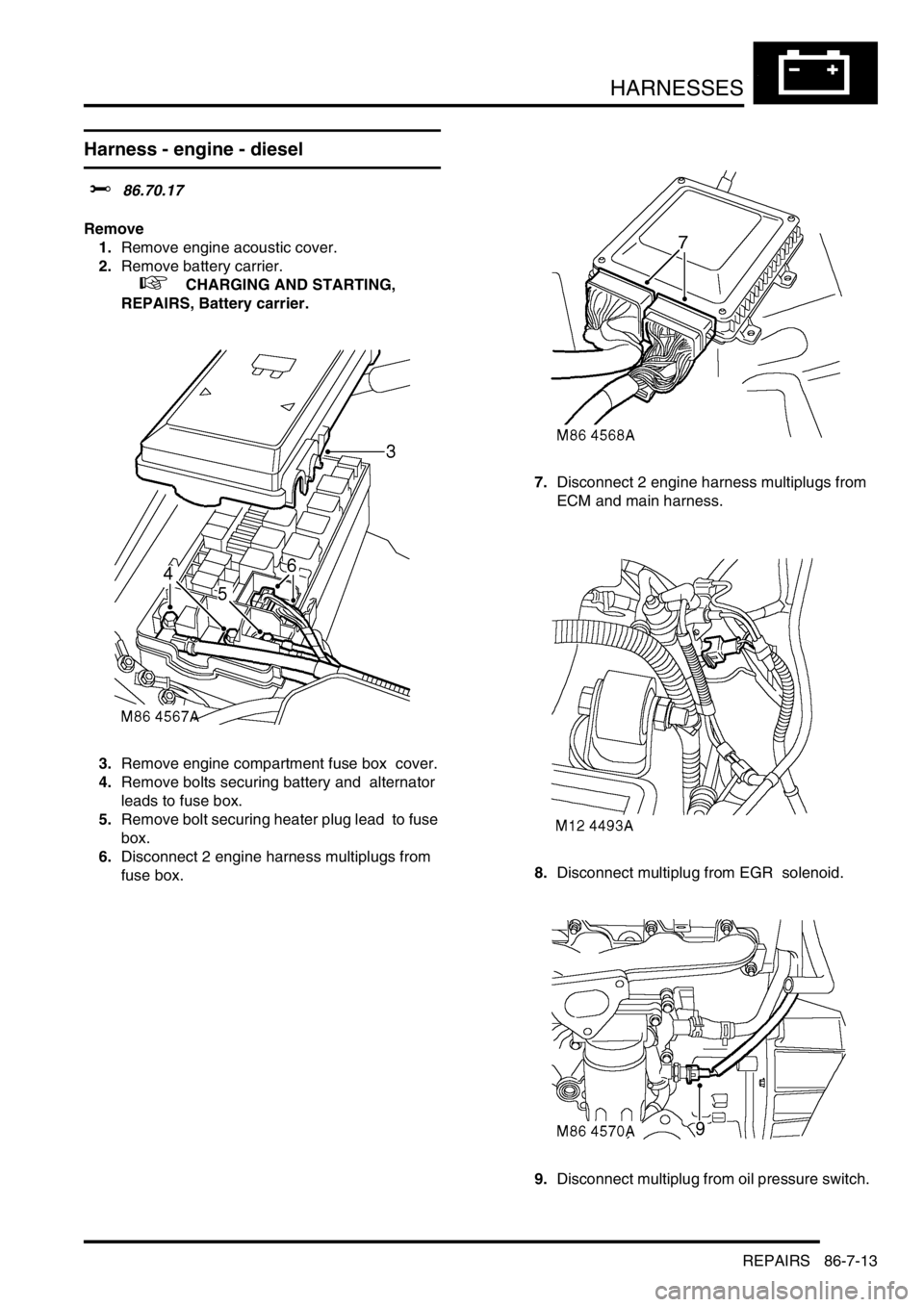
3.Remove engine compartment fuse box cover.
4.Remove bolts securing battery and alternator
leads to fuse box.
5.Remove bolt securing heater plug lead to fuse
box.
6.Disconnect 2 engine harness multiplugs from
fuse box. 7.Disconnect 2 engine harness multiplugs from
ECM and main harness.
8.Disconnect multiplug from EGR solenoid.
9.Disconnect multiplug from oil pressure switch.
Page 1587 of 1672
HARNESSES
86-7-16 REPAIRS
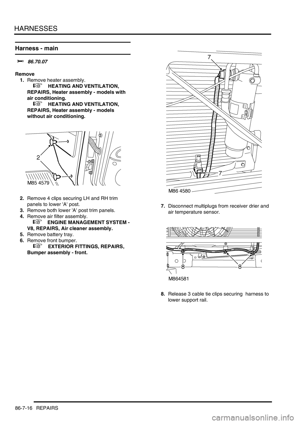
Harness - main
$% 86.70.07
Remove
1.Remove heater assembly.
+ HEATING AND VENTILATION,
REPAIRS, Heater assembly - models with
air conditioning.
+ HEATING AND VENTILATION,
REPAIRS, Heater assembly - models
without air conditioning.
2.Remove 4 clips securing LH and RH trim
panels to lower 'A' post.
3.Remove both lower 'A' post trim panels.
4.Remove air filter assembly.
+ ENGINE MANAGEMENT SYSTEM -
V8, REPAIRS, Air cleaner assembly.
5.Remove battery tray.
6.Remove front bumper.
+ EXTERIOR FITTINGS, REPAIRS,
Bumper assembly - front.7.Disconnect multiplugs from receiver drier and
air temperature sensor.
8.Release 3 cable tie clips securing harness to
lower support rail.