2002 LAND ROVER DISCOVERY ac compre
[x] Cancel search: ac comprePage 1085 of 1672
BRAKES
70-40 REPAIRS
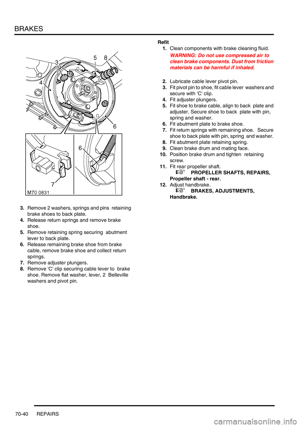
3.Remove 2 washers, springs and pins retaining
brake shoes to back plate.
4.Release return springs and remove brake
shoe.
5.Remove retaining spring securing abutment
lever to back plate.
6.Release remaining brake shoe from brake
cable, remove brake shoe and collect return
springs.
7.Remove adjuster plungers.
8.Remove 'C' clip securing cable lever to brake
shoe. Remove flat washer, lever, 2 Belleville
washers and pivot pin. Refit
1.Clean components with brake cleaning fluid.
WARNING: Do not use compressed air to
clean brake components. Dust from friction
materials can be harmful if inhaled.
2.Lubricate cable lever pivot pin.
3.Fit pivot pin to shoe, fit cable lever washers and
secure with 'C' clip.
4.Fit adjuster plungers.
5.Fit shoe to brake cable, align to back plate and
adjuster. Secure shoe to back plate with pin,
spring and washer.
6.Fit abutment plate to brake shoe.
7.Fit return springs with remaining shoe. Secure
shoe to back plate with pin, spring and washer.
8.Fit abutment plate retaining spring.
9.Clean brake drum and mating face.
10.Position brake drum and tighten retaining
screw.
11.Fit rear propeller shaft.
+ PROPELLER SHAFTS, REPAIRS,
Propeller shaft - rear.
12.Adjust handbrake.
+ BRAKES, ADJUSTMENTS,
Handbrake.
Page 1089 of 1672
BRAKES
70-44 REPAIRS
Refit
1.Rotate disc by hand and scrape all scale and
rust from around edge of disc. Clean location
surfaces on caliper bracket.
2.Clean dust from brake parts using brake
cleaning fluid.
WARNING: Do not use compressed air to
clean brake components. Dust from friction
materials can be harmful if inhaled.
3.Fit brake pads to caliper carrier.
4.Position caliper housing to carrier, align flats on
guide pins with caliper housing.
5.Fit guide pin bolts and tighten to 30 Nm (22
lbf.ft).
6.Clean banjo bolt and fit new sealing washers.
7.Position hose to caliper and tighten banjo bolt
to 32 Nm (24 lbf.ft).
8.Remove clamp from brake hose.
9.Bleed brake system.
+ BRAKES, ADJUSTMENTS, Brake
system bleeding.
10.Fit road wheel(s) and tighten nuts to 140 Nm
(103 lbf.ft).
11.Remove stand(s) and lower vehicle.
Housing - caliper - rear
$% 70.55.25
Remove
1.Raise rear of vehicle, one side.
WARNING: Do not work on or under a
vehicle supported only by a jack. Always
support the vehicle on safety stands.
2.Remove road wheel(s).
3.Clamp brake hose to prevent fluid loss.
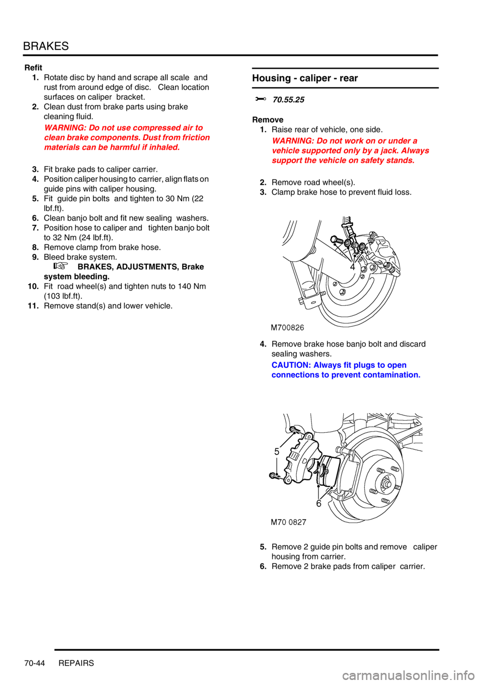
4.Remove brake hose banjo bolt and discard
sealing washers.
CAUTION: Always fit plugs to open
connections to prevent contamination.
5.Remove 2 guide pin bolts and remove caliper
housing from carrier.
6.Remove 2 brake pads from caliper carrier.
Page 1090 of 1672
BRAKES
REPAIRS 70-45
Refit
1.Rotate disc by hand and scrape all scale and
rust from around edge of disc. Clean location
surfaces on caliper bracket.
2.Clean dust from brake parts using brake
cleaning fluid.
WARNING: Do not use compressed air to
clean brake components. Dust from friction
materials can be harmful if inhaled.
3.Fit brake pads to caliper carrier.
4.Position caliper housing to carrier, align flats on
guide pins with caliper housing.
5.Fit guide pin bolts and tighten to 30 Nm (22
lbf.ft).
6.Clean banjo bolt and fit new sealing washers.
7.Position hose to caliper and tighten banjo bolt
to 32 Nm (24 lbf.ft).
8.Remove clamp from brake hose.
9.Bleed brakes.
+ BRAKES, ADJUSTMENTS, Brake
system bleeding.
10.Fit road wheel(s) and tighten nuts to 140 Nm
(103 lbf.ft).
11.Remove stand(s) and lower vehicle.
ECU - Self levelling and anti locking
brakes (SLABS)
$% 70.65.01
Remove
1.Remove BCU.
+ BODY CONTROL UNIT, REPAIRS,
Body control unit (BCU).
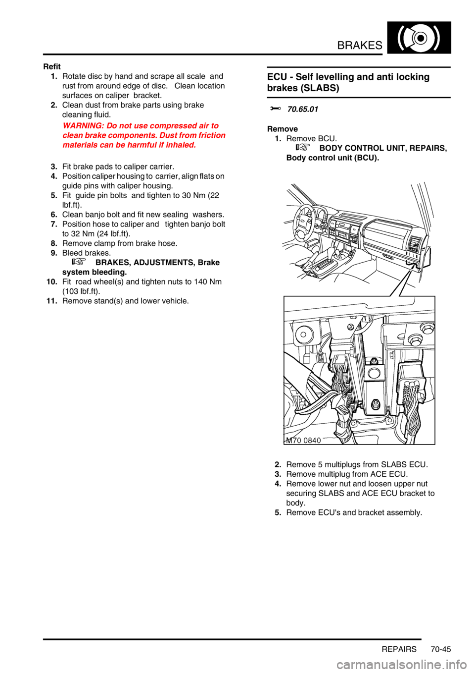
2.Remove 5 multiplugs from SLABS ECU.
3.Remove multiplug from ACE ECU.
4.Remove lower nut and loosen upper nut
securing SLABS and ACE ECU bracket to
body.
5.Remove ECU's and bracket assembly.
Page 1286 of 1672
PANEL REPAIRS
REPAIRS 77-2-37
Sill outer assembly
Remove
1.Disconnect both battery leads, negative lead
first.
2.Disconnect leads/multiplug from alternator.
3.Remove RH or LH front wing.
+ EXTERIOR FITTINGS, REPAIRS,
Wing - front - up to 03MY.
4.Remove RH or LH front door.
+ DOORS, REPAIRS, Door - front.
5.Remove RH or LH rear door.
+ DOORS, REPAIRS, Door - rear.
6.Remove RH or LH sill finisher.
7.Remove RH or LH 'A' post inner lower
finishers.
8.Remove RH or LH front seat.
+ SEATS, REPAIRS, Seat - front.
9. LH side: Remove power amplifier and EAT
ECU.
+ IN CAR ENTERTAINMENT,
REPAIRS, Amplifier - power.
10. RH side: Remove CD autochanger.
+ IN CAR ENTERTAINMENT,
REPAIRS, CD autochanger.
11.Remove rear seats.
+ SEATS, REPAIRS, Seat - rear.
12.Remove RH or LH front seat belt.
+ RESTRAINT SYSTEMS, REPAIRS,
Seat belt - front.
13.Remove tread plates from front and rear door
apertures.
14.Release carpet and position aside.
15.Remove front and rear door aperture seals.
16.Release relevant wiring from 'A' post, 'B/C' post
and sill areas, and position aside.
17.Remove loadspace lower trim casing.
+ INTERIOR TRIM COMPONENTS,
REPAIRS, Trim casing - side - loadspace.
18. RH side: Remove lower ACE accelerometer.
+ FRONT SUSPENSION, REPAIRS,
Accelerometer - ACE - lower.
19. LH side: Remove SLS air compressor unit.
+ REAR SUSPENSION, REPAIRS,
Compressor unit - air - SLS.
20. Models with rear A/C: Recover refrigerant
from A/C system and remove A/C pipes from
LH sill.
+ AIR CONDITIONING, REFRIGERANT
RECOVERY, RECYCLING AND
RECHARGING, Refrigerant recovery,
recycling and recharging.
21.Remove 2 bolts securing body to chassis.Repair
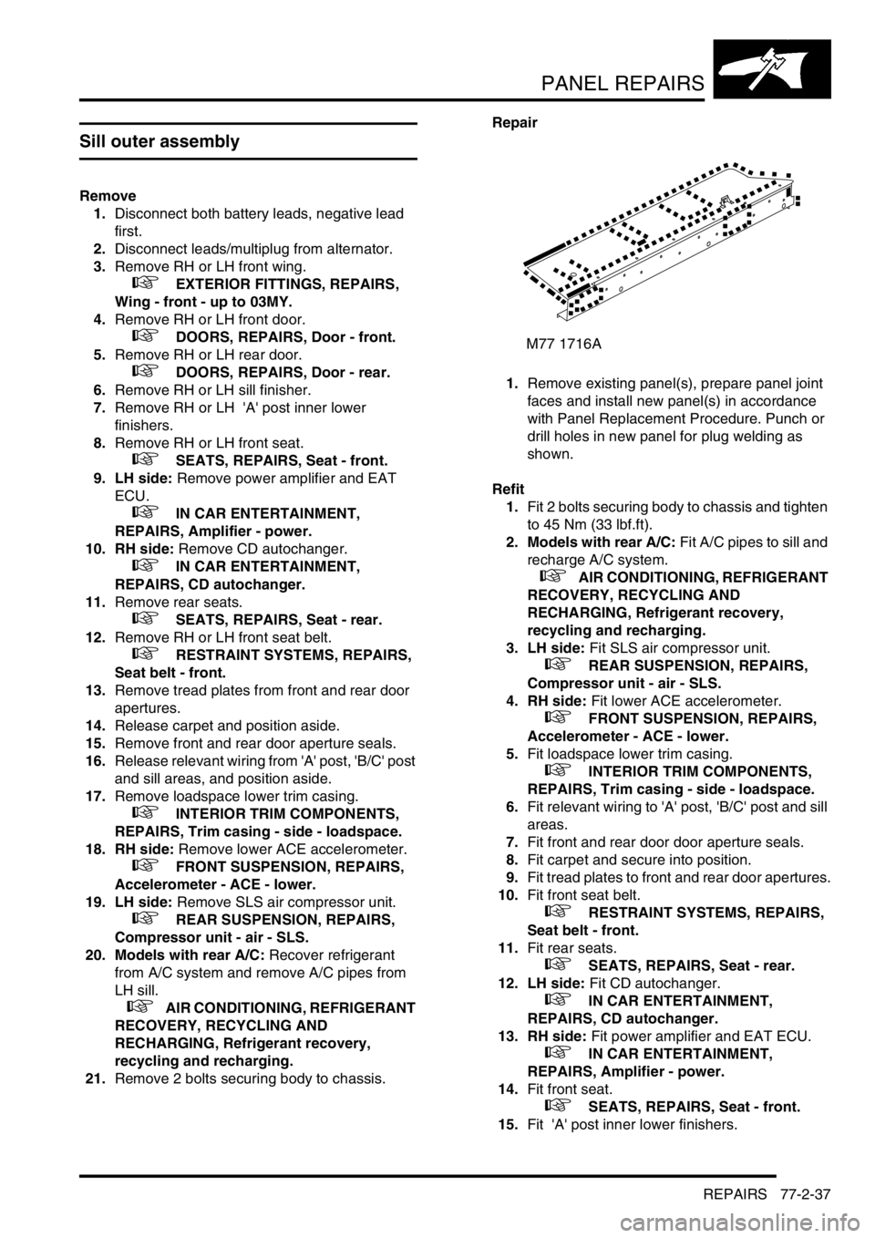
1.Remove existing panel(s), prepare panel joint
faces and install new panel(s) in accordance
with Panel Replacement Procedure. Punch or
drill holes in new panel for plug welding as
shown.
Refit
1.Fit 2 bolts securing body to chassis and tighten
to 45 Nm (33 lbf.ft).
2. Models with rear A/C: Fit A/C pipes to sill and
recharge A/C system.
+ AIR CONDITIONING, REFRIGERANT
RECOVERY, RECYCLING AND
RECHARGING, Refrigerant recovery,
recycling and recharging.
3. LH side: Fit SLS air compressor unit.
+ REAR SUSPENSION, REPAIRS,
Compressor unit - air - SLS.
4. RH side: Fit lower ACE accelerometer.
+ FRONT SUSPENSION, REPAIRS,
Accelerometer - ACE - lower.
5.Fit loadspace lower trim casing.
+ INTERIOR TRIM COMPONENTS,
REPAIRS, Trim casing - side - loadspace.
6.Fit relevant wiring to 'A' post, 'B/C' post and sill
areas.
7.Fit front and rear door door aperture seals.
8.Fit carpet and secure into position.
9.Fit tread plates to front and rear door apertures.
10.Fit front seat belt.
+ RESTRAINT SYSTEMS, REPAIRS,
Seat belt - front.
11.Fit rear seats.
+ SEATS, REPAIRS, Seat - rear.
12. LH side: Fit CD autochanger.
+ IN CAR ENTERTAINMENT,
REPAIRS, CD autochanger.
13. RH side: Fit power amplifier and EAT ECU.
+ IN CAR ENTERTAINMENT,
REPAIRS, Amplifier - power.
14.Fit front seat.
+ SEATS, REPAIRS, Seat - front.
15.Fit 'A' post inner lower finishers.
M77 1716A
Page 1312 of 1672
BODY SEALING MATERIALS
MATERIALS AND APPLICATIONS 77-3-5
Cooper Pegler Falcon Junior Pneumatic Gun (Airless)
Intended primarily for applying transit wax, this pneumatic sprayer has a 5-litre container with integral hand pump and
provides an effective means of wax spraying without the need for compressed air or additional services.
A selection of nozzles, lances, hose lengths and a trigger valve assembly with integral filter allows flexibility in use.
Additional applications include general maintenance, wax injection and paint application. Heavy-bodied materials
may also be applied. All parts are fully replaceable and a wide range of nozzle configurations is available.
SATA Schutz Gun Model UBE
The SATA Schutz Gun is approved for the retreatment of vehicle underbody areas with protective coatings as
supplied in 1 litre, purpose-designed 'one-way' containers. The screw thread fitting (female on the gun) is standard
to most Schutz-type packs.
SATA HKD1 Wax Injection Injection Equipment
This equipment is approved for carrying out cavity wax re-treatment. The SATA HKD1 set comprises a high quality
forged gun with 1-litre pressure feed container, a flexible nylon lance, a straight 1100 mm (43.307 in) steel lance and
hooked- wand lance. A quick-change coupling is provided as a standard fitting to allow lances to be easily
interchanged. Each lance has an integral, machined nozzle with specialised spray characteristics to suit the type of
box section to be treated.
NOTE: Always clean gun after use with appropriate solvent to maintain efficiency.
Specifications of Model UBE:
Air consumption 7 ft
3/min (200 litres/min) @ 45 lbf.in2
Weight: 23.3oz (220 grams)
Page 1313 of 1672
BODY SEALING MATERIALS
77-3-6 MATERIALS AND APPLICATIONS
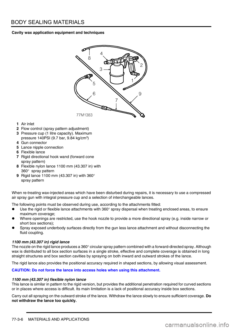
Cavity wax application equipment and techniques
1Air inlet
2Flow control (spray pattern adjustment)
3Pressure cup (1 litre capacity). Maximum
pressure 140PSI (9.7 bar, 9.84 kg/cm
3)
4Gun connector
5Lance nipple connection
6Flexible lance
7Rigid directional hook wand (forward cone
spray pattern)
8Flexible nylon lance 1100 mm (43.307 in) with
360
° spray pattern
9Rigid lance 1100 mm (43.307 in) with 360
°
spray pattern
When re-treating wax-injected areas which have been disturbed during repairs, it is necessary to use a compressed
air spray gun with integral pressure cup and a selection of interchangeable lances.
The following points must be observed during use, according to the attachments fitted:
lUse the rigid or flexible lance attachments with 360
° spray dispersal when treating enclosed areas, to ensure
maximum coverage;
lWhere openings are restricted, use the hook nozzle to provide a more directional spray (e.g. inside narrow or
short box sections);
lSpray exposed underbody surfaces directly from the gun less lance attachment and without disconnecting the
fluid coupling.
1100 mm (43.307 in) rigid lance
The nozzle on the rigid lance produces a 360
° circular spray pattern combined with a forward-directed spray. Although
wax is distributed to all box section surfaces in a single stroke, effective and complete coverage is obtained in long
straight structures and box section cavities by spraying on both inward and outward strokes of the lance.
The rigid lance also provides the positional accuracy required in shaped sections, by allowing visual assessment.
CAUTION: Do not force the lance into access holes when using this attachment.
1100 mm (43.307 in) flexible nylon lance
This lance is similar in pattern to the rigid version, but provides the additional penetration required for curved sections
or in places where access is difficult. Its main limitation is a lack of positional accuracy inside box sections.
Carry out all spraying on the outward stroke of the lance. Withdraw the lance slowly to ensure sufficient coverage. Do
not withdraw the lance too quickly.
Page 1322 of 1672

CORROSION PREVENTION AND SEALING
CORROSION PREVENTION 77-4-7
The checks described above are intended to be visual only. It is not intended that the operator should remove trim
panels, finishers, rubbing strips or sound-deadening materials when checking the vehicle for corrosion and paint
damage.
With the vehicle on a lift, and using an inspection or spot lamp, visually check for the following:
lCorrosion damage and damaged paintwork, condition of underbody sealer on front and rear lower panels, sills
and wheel arches;
lDamage to underbody sealer. Corrosion in areas adjacent to suspension mountings and fuel tank fixings.
NOTE: The presence of small blisters in the underbody sealer is acceptable, providing they do not expose bare metal.
Pay special attention to signs of damage caused to panels or corrosion protection material by incorrect jack
positioning.
WARNING: It is essential to follow the correct jacking and lifting procedures.
With the vehicle lowered, visually check for evidence of damage and corrosion on all visible painted areas, in
particular the following:
lFront edge of bonnet;
lVisible flanges in engine compartment;
lLower body and door panels.
Rectify any bodywork damage or evidence of corrosion found during inspection as soon as is practicable, both to
minimise the extent of the damage and to ensure the long term effectiveness of the factory-applied corrosion
prevention treatment. Where the cost of rectification work is the owner's responsibility, the Dealer must advise the
owner and endorse the relevant documentation accordingly.
Where corrosion has become evident and is emanating from beneath a removable component (e.g. trim panel,
window glass, seat etc.), remove the component as required to permit effective rectification.
Underbody protection repairs
Whenever body repairs are carried out, ensure that full sealing and corrosion protection treatments are reinstated.
This applies both to the damaged areas and also to areas where protection has been indirectly impaired, as a result
either of accident damage or repair operations.
Remove corrosion protection from the damaged area before straightening or panel beating. This applies in particular
to panels coated with wax, PVC underbody sealer, sound deadening pads etc.
WARNING: DO NOT use oxy-acetylene gas equipment to remove corrosion prevention materials. Large
volumes of fumes and gases are liberated by these materials when they burn.
NOTE: Equipment for the removal of tough anti-corrosion sealers offers varying degrees of speed and effectiveness.
The compressed air-operated scraper (NOT an air chisel) offers a relatively quiet mechanical method using an
extremely rapid reciprocating action. Move the operating end of the tool along the work surface to remove the material.
The most common method of removal is by means of a hot air blower with integral scraper.
Another tool, and one of the most efficient methods, is the rapid-cutting 'hot knife'. This tool uses a wide blade and is
quick and versatile, able to be used easily in profiled sections where access is otherwise difficult.
Use the following procedure when repairing underbody coatings:
1Remove existing underbody coatings
2After panel repair, clean the affected area with a solvent wipe, and treat bare metal with an etch phosphate
material
3Re-prime the affected area
CAUTION: DO NOT, under any circumstances, apply underbody sealer directly to bare metal surfaces.
4Replace all heat-fusible plugs which have been disturbed. Where such plugs are not available use rubber
grommets of equivalent size, ensuring that they are embedded in sealer
5Mask off all mounting faces from which mechanical components, hoses and pipe clips, have been removed.
Underbody sealer must be applied before such components are refitted
6Brush sealer into all exposed seams
7Spray the affected area with an approved service underbody sealer
8Remove masking from component mounting faces, and touch-in where necessary. Allow adequate drying time
before applying underbody wax
Page 1323 of 1672
CORROSION PREVENTION AND SEALING
77-4-8 CORROSION PREVENTION
After refitting mechanical components, including hoses and pipes and other fixtures, mask off the brake discs and
apply a coat of approved underbody wax.
NOTE: Where repairs include the application of finish paint coats in the areas requiring underbody wax, carry out paint
operations before applying wax.
Cavity wax injection
Areas treated with cavity wax are shown in the previous figures. After repairs, always re-treat these areas with an
approved cavity wax. In addition, treat all interior surfaces which have been disturbed during repairs whether they
have been treated in production or not. This includes all box members, cavities and door interiors. It is permissible to
drill extra holes for access where necessary, provided these are not positioned in load-bearing members. Ensure that
such holes are treated with a suitable zinc rich primer, brushed with wax and then sealed with a rubber grommet.
Before wax injection, ensure that the cavity to be treated is free from any contamination or foreign matter. Where
necessary, clear out any debris using compressed air.
Ensure that cavity wax is applied AFTER the final paint process and BEFORE refitting any trim components.
During application, ensure that the wax covers all flange and seam areas and that it is adequately applied to all
repaired areas of both new and existing panels.
It should be noted that new panel assemblies and complete body shells are supplied without wax injection treatment.
Ensure that such treatment is carried out after repairs.
Effective cavity wax protection is vital. Always observe the following points:
lComplete all paint refinish operations before wax application;
lClean body panel areas and blow-clean cavities if necessary, before treatment;
lMaintain a temperature of 18
° C (64° F) during application and drying;
lCheck the spray pattern of injection equipment;
lMask off all areas not to be wax coated and which could be contaminated by wax overspray;
lRemove body fixings, such as seat belt retractors, if contamination is at all likely;
lMove door glasses to fully closed position before treating door interiors;
lTreat body areas normally covered by trim before refitting items;
lCheck that body and door drain holes are clear after the protective wax has dried;
lKeep all equipment clean, especially wax injection nozzles.
Underbody wax
The underbody wax must be reinstated following all repairs affecting floor panels. The wax is applied over paints and
underbody sealers.
Remove old underbody wax completely from a zone extending at least 200 mm (7.874 in) beyond the area where new
underbody sealer is to be applied.
Engine bay wax
Reinstate all protective engine bay wax disturbed during repairs using an approved material.
Where repairs have involved replacement of engine bay panels, treat the entire engine compartment including all
components, clips and other fixtures with an approved underbonnet lacquer or wax.
+ BODY SEALING MATERIALS, MATERIALS AND APPLICATIONS, Approved materials.