2002 LAND ROVER DISCOVERY ac compre
[x] Cancel search: ac comprePage 1011 of 1672

REAR SUSPENSION
64-6 DESCRIPTION AND OPERATION
Description
General
The rear suspension comprises two dampers, two radius arms, a Watts linkage and an anti-roll bar assembly. On
vehicles without Self Levelling Suspension (SLS) coil springs are used. On vehicles with SLS air springs are used.
The anti-roll bar is an essential part of the rear suspension. On vehicles without ACE, a conventional 'passive' anti-
roll bar is fitted. On vehicles fitted with the ACE system, a thicker diameter anti-roll bar, known as a torsion bar, is used
with an actuator at one end.
+ FRONT SUSPENSION, DESCRIPTION AND OPERATION, Description - ACE.
The hydraulic dampers and springs provide springing for each rear wheel. The long travel dampers, springs and
radius arms provide maximum axle articulation and wheel travel for off-road driving. The rear axle is controlled
longitudinally by two forged steel radius arms and transversely by a Watts linkage.
Radius arms
Each radius arm is manufactured from forged steel. Two bushes are pressed into the rear of the radius arm. The rear
of the radius arm is located between a fabricated bracket on the axle and secured through the bushes with two bolts
and nuts. A bush is pressed into the forward end of the radius arm which is located in a fabricated bracket on each
chassis longitudinal and secured through the bush with a bolt and nut. Each radius arm is similar in its construction
to the front radius arms. The rear radius arms are shorter than the front and have a lug for attachment of the SLS
height sensor (when fitted).
The radius arms prevent longitudinal movement of the rear axle and because of their length allow maximum axle
articulation. The stiffness of the bushes in each radius arm also contributes to the vehicle roll stiffness.
Each radius arm has a notch on its lower edge which provides location for the vehicle jack.
Dampers
Two conventional telescopic dampers are used to control body/axle movement. The upper damper mounting is fitted
with a bush which locates in a bracket on the chassis longitudinal. The damper is secured with a bolt which screws
into a captive nut on the bracket. The lower damper mounting is also fitted with a bush and locates in a fabricated
bracket attached to the rear axle. The lower mounting is secured with a bolt which screws into a captive nut on the
bracket. The upper and lower bushes are replaceable items.
Air springs (vehicles with SLS)
On vehicles with SLS fitted, air springs are fitted between the rear axle and the chassis. Each spring is located at its
base on a fabricated platform on the rear axle. The top of the spring locates in a fabricated bracket attached to the
outside of each chassis longitudinal.
The plastic base of the air spring has two lugs which locate in a slotted hole in the rear axle platform. The spring is
secured by rotating the spring through 90
°, locating the lug in the platform. The plastic top of the air spring has two
grooved pins which locate in holes in the bracket on the chassis. Two spring clips locate on the grooved pins and
retain the top of the spring in position.
Each air spring comprises a top plate assembly, an air bag and a base piston. The air bag is attached to the top plate
and the piston with a crimped ring. The air bag is made from a flexible rubber material which allows the bag to expand
with air pressure and deform under load. The top plate assembly comprises the plastic top plate with two bonded
grooved pins on its top face. In the centre of the top face is a female connector which allows for the attachment of the
air hose from the SLS compressor. The piston is made from plastic and is shaped to allow the air bag to roll over its
outer diameter. The base of the piston is recessed with a boss moulded in the centre. The boss has two lugs which
provide attachment to the axle platform.
Page 1012 of 1672

REAR SUSPENSION
DESCRIPTION AND OPERATION 64-7
Coil springs (vehicles without SLS)
On vehicles without SLS fitted, coil springs are fitted between the rear axle and the chassis in place of the SLS air
springs. Each spring is located at its base by the lower spring seat which is secured to a fabricated platform on the
rear axle with two bolts. The top of each spring is located in the upper spring seat. The upper spring seat comprises
a pressed metal plate with an outer coating of natural rubber bonded to the plate. The upper spring seat is retained
in position by the compression of the spring.
Coil Spring Specifications – Models up to 03 Model Year
The rear coil springs are of the variable rate type and are manufactured from silicon manganese 16.5 mm (0.65 in.)
diameter bar. Each spring has 9 coils and a free length of 385 mm (15.1 in.). The variable rate of the spring is achieved
by the active coils at one end being closer together. The rear coil spring is identified by a purple stripe painted on a
number of coils.
Coil Spring Specifications – Models From 03 Model Year
The introduction of the 03MY vehicle introduced a range of additional rear coil spring fitments. These were introduced
as a package to optimise vehicle trim heights.
The coil springs are manufactured from silicon manganese 16.35 mm (0.64 in.) diameter bar for springs on five seater
models and 16.57 mm (0.65 in.) diameter bar on seven seater models. The following spring data table shows the
colour codes, number of coils and spring free length.
Spring Data
The following table shows spring fitment applicability.
Spring Fitment Applicability
Watts linkage
A Watts linkage is used to ensure that the rear axle remains centrally located. The Watts linkage comprises two
transverse links and a pivot housing. The transverse links and pivot housing allow the rear axle to move vertically
without any transverse movement.
The transverse links are made from fabricated and welded steel. Each transverse link has a bush press fitted into a
housing at one end. The opposite end has a forked bracket with two cross holes.
The pivot housing is made from cast iron. Three bushes are press fitted in the housing, one in the centre and one at
each end.
Colour Code Total No. of Coils Free Length Model
Brown/Orange 8.73 384.7 mm (15.14 in) 5 Seat
Grey/Orange 8.73 392 mm (15.43 in) 5 Seat
Yellow/Grey 8.73 376.6 mm (14.82 in) 5 Seat
Pink/Grey 8.73 400.3 mm (15.75 in) 5 Seat
Blue/Grey 9.10 387.8 mm (15.26 in) 7 Seat
Green/Grey 9.10 395.2 mm (15.55 in) 7 Seat
White/Grey 9.10 380.6 mm (14.98 in) 7 Seat
Left Hand Drive Right Hand Drive
Both Sides RH Side LH Side
Brown/Orange Grey/Orange Yellow/Grey
Grey Orange Pink/Grey Brown/Orange
Blue/Grey Green/Grey White/Grey
Page 1018 of 1672

REAR SUSPENSION
DESCRIPTION AND OPERATION 64-13
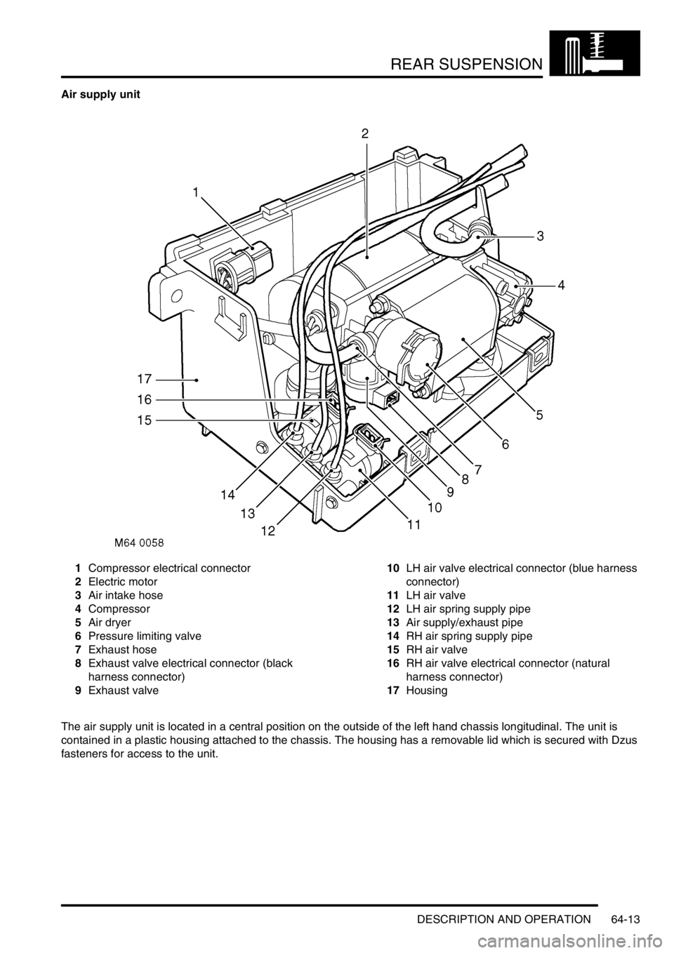
Air supply unit
1Compressor electrical connector
2Electric motor
3Air intake hose
4Compressor
5Air dryer
6Pressure limiting valve
7Exhaust hose
8Exhaust valve electrical connector (black
harness connector)
9Exhaust valve10LH air valve electrical connector (blue harness
connector)
11LH air valve
12LH air spring supply pipe
13Air supply/exhaust pipe
14RH air spring supply pipe
15RH air valve
16RH air valve electrical connector (natural
harness connector)
17Housing
The air supply unit is located in a central position on the outside of the left hand chassis longitudinal. The unit is
contained in a plastic housing attached to the chassis. The housing has a removable lid which is secured with Dzus
fasteners for access to the unit.
Page 1019 of 1672

REAR SUSPENSION
64-14 DESCRIPTION AND OPERATION
The air supply unit comprises a 12 V electric motor, a compressor and air dryer unit, a pressure limiting valve, an
exhaust valve and two air supply control valves. The exhaust and control valves are solenoid operated responding to
signals from the SLABS ECU. The electric motor, compressor, air dryer and pressure limiting and exhaust valve are
mounted on flexible rubber mountings to reduce operating noise.
The electric motor drives a crank with an eccentric pin to which a connecting rod is attached. The connecting rod has
a piston which fits in the bore of the compressor. Operation of the motor rotates the crank, moving the piston in the
bore of the compressor.
The compressor is attached with Allen bolts to the motor housing and sealed with an O-ring. Attached to the
compressor is the air dryer which contains a silicate box for removing moisture from the compressed air. Air supplied
to inflate the air springs passes through the air dryer. When the air springs are deflated, the exhaust air also passes
through the air dryer, removing the moisture from the unit and expelling it to atmosphere.
Attached to end of the air dryer unit is the pressure limiting valve. The valve protects the air springs from over inflation.
The pressure limiting valve also operates when the exhaust valve is opened. The valve is pneumatically operated,
responding to air pressure applied to it.
The exhaust valve is also located with the pressure limiting valve. The exhaust valve is solenoid operated by the ECU
and directs air from the air springs and control valves to atmosphere when required.
The two air control valves for the LH and RH air springs are located at the forward end of the housing. Each valve is
connected to the compressor/air dryer unit through a shared single pipe which directs air to and from the air springs.
Each control valve is individually operated by the ECU.
All air connections to and from the air supply unit are made through the SLS air harness which is located along the
left hand chassis longitudinal.
If faults occur with the air supply unit, fault codes are stored in the SLABS ECU. These fault codes cover the
compressor power supply and the LH and RH air control valves and the exhaust valve. The current and past fault
codes can be retrieved with TestBook. TestBook can also be used to operate the compressor and the valves for
diagnostic purposes.
Air intake filter
The air intake filter is located in the left hand 'E' post, behind the tail lamp assembly. The filter comprises a plastic
moulded housing which contains two filters of differing density to remove particulate matter from the air drawn in by
the compressor. The air intake filter has a pipe which is connected to the SLS air harness by a quick release
connector. The air intake filter must be replaced as an assembly.
Air intake/Exhaust silencer
The air intake/exhaust silencer is located on the outside of the left hand chassis longitudinal, behind the air supply
unit. The silencer is an integral part of the SLS air harness and cannot be serviced individually.
The intake and exhaust air to and from the compressor passes through the silencer. The plastic moulded silencer has
two chambers. One chamber reduces system exhaust noise and the other dampens intake air pulses produced by
the compressor.
Page 1022 of 1672

REAR SUSPENSION
DESCRIPTION AND OPERATION 64-17
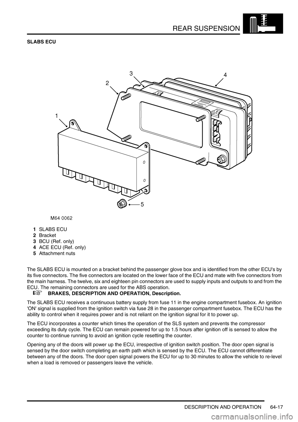
SLABS ECU
1SLABS ECU
2Bracket
3BCU (Ref. only)
4ACE ECU (Ref. only)
5Attachment nuts
The SLABS ECU is mounted on a bracket behind the passenger glove box and is identified from the other ECU's by
its five connectors. The five connectors are located on the lower face of the ECU and mate with five connectors from
the main harness. The twelve, six and eighteen pin connectors are used to supply inputs and outputs to and from the
ECU. The remaining connectors are used for the ABS operation.
+ BRAKES, DESCRIPTION AND OPERATION, Description.
The SLABS ECU receives a continuous battery supply from fuse 11 in the engine compartment fusebox. An ignition
'ON' signal is supplied from the ignition switch via fuse 28 in the passenger compartment fusebox. The ECU has the
ability to control when it requires power and is not reliant on the ignition signal for it to power up.
The ECU incorporates a counter which times the operation of the SLS system and prevents the compressor
exceeding its duty cycle. The ECU can remain powered for up to 1.5 hours after ignition off is sensed to allow the
counter to continue running to avoid an ignition cycle resetting the counter.
Opening any of the doors will power up the ECU, irrespective of ignition switch position. The door open signal is
sensed by the door switch completing an earth path which is sensed by the ECU. The ECU cannot differentiate
between any of the doors. The door open signal powers the ECU for up to 30 minutes to allow the vehicle to re-level
when a load is removed or passengers leave the vehicle.
Page 1023 of 1672

REAR SUSPENSION
64-18 DESCRIPTION AND OPERATION
The ECU supplies a 5 V current to each of the height sensors. Each height sensor uses the current to supply an
analogue input to the ECU. The ECU can calculate from the input received from each height sensor the height of the
vehicle and can then power the air supply unit as necessary to raise or lower one or both air springs to level the
vehicle.
When SLS compressor operation is required, the ECU provides a battery supply to energise the SLS relay located in
the engine compartment fusebox. When the relay contacts close, a 12 V supply passes through fusible link 9 in the
engine compartment fusebox, through the relay contacts and operates the air supply unit compressor. The ECU will
then supply power to operate one or both air control valve solenoids and/or the exhaust valve solenoid to inflate or
deflate the air springs as required. The compressor does not need to be powered to deflate the air springs.
The ECU also controls the operation of the SLS audible warning, the SLS warning lamp and the ORM warning lamp.
When the ignition is switched to position II, the ECU performs a three second bulb check and illuminates the SLS and
ORM warning lamps in the instrument pack to check for operation. When the system is operating or a fault is sensed
by the ECU, the ECU will operate the appropriate warning lamp and audible warning as required. The audible warning
is operated by the Body Control Unit (BCU) when it receives a signal from the SLABS ECU. The audible warning is
emitted from a speaker at the rear of the instrument pack.
Depressing the ORM switch for a minimum of 0.5 seconds, completes an earth which the ECU uses as a signal to
initiate the ORM if conditions allow. When the ECU starts ORM, the same earth that was completed by the ORM
switch is pulled to earth by the ECU to activate the ORM warning lamp. The ECU checks for a further operation of the
ORM switch by continuously and very quickly removing the earth for the ORM warning lamp. If the ORM switch is
operated for more than 0.5 seconds, the ECU will detect this and de-activate the ORM.
The SLS part of the SLABS ECU also uses the road speed data generated within the SLABS ECU by the ABS system.
Operation of ORM and extended mode are road speed sensitive and use the ABS signal to monitor the vehicle speed.
When the accessory remote handset is used for the SLS lower and raise functions, the handset transmits RF signals
which are received by the same RF receiver used for the alarm/remote door locking system. The RF receiver passes
this data as a 25 Hz PWM signal to the BCU. The BCU then transmits this data to the SLABS ECU as raise or lower
data. TestBook is required to program the BCU for remote handset operation.
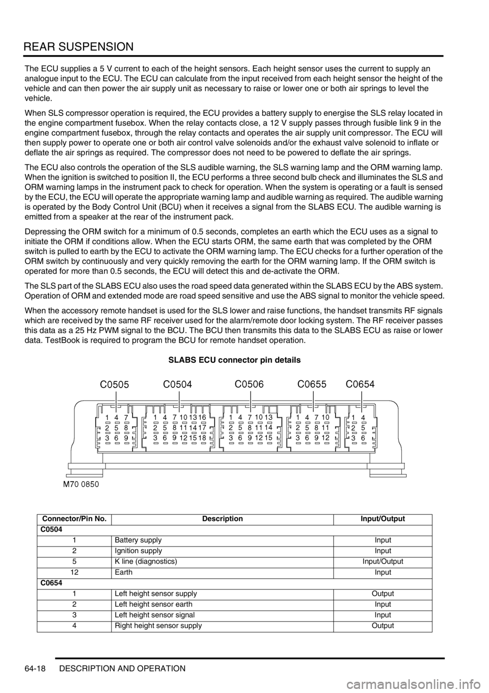
SLABS ECU connector pin details
Connector/Pin No. Description Input/Output
C0504
1 Battery supply Input
2 Ignition supply Input
5 K line (diagnostics) Input/Output
12 EarthInput
C0654
1 Left height sensor supply Output
2 Left height sensor earth Input
3 Left height sensor signal Input
4 Right height sensor supply Output
Page 1024 of 1672

REAR SUSPENSION
DESCRIPTION AND OPERATION 64-19
Failure modes
Failures are indicated by the SLS warning lamp in the bottom left corner of the instrument pack illuminating
continuously in an amber colour. The following tables show the type of system failures and their effects on the system
operation.
Height sensors
Door Switch Inputs
SLS off-road mode switch
Air supply unit air control valves
Air supply unit compressor
5 Right height sensor earth Input
6 Right height sensor signal Input
C0655
1 Driver's door switch Input
2 Passenger and tail door switches Input
3 Left air valve Output
4 Right air valve Output
5 Exhaust valve Output
6 Air compressor (SLS relay) Output
7 Audible warning Output
8 SLS warning lamp Output
11 ORM switch/ORM warning lamp Input/Output
12 Remote handset raise/lower signal Input
Connectors and pins not listed are either not used or used by the brakes system.
+ BRAKES, DESCRIPTION AND OPERATION, Description.
Failure Effect
Sensor output stuck at 5 V Vehicle will not level
Sensor output stuck at 0 V Vehicle will not level
Mechanical link between radius arm and sensor broken Vehicle will not level
Failure Effect
Harness leads for open doors are are broken or shorted to
V Batt.Air suspension levels when one or more doors are open
Harness leads to door(s) shorted to earth Air suspension will not level
Failure Effect
Fault in wiring harness Off-road mode cannot be selected
Failure of off-road mode switch Off-road mode is activated when switch has not been
selected
Failure Effect
Valves open or short circuit Vehicle does not level or levels unevenly
Failure Effect
Faulty relay, harness fault or compressor fault Vehicle does not level upwards
Page 1025 of 1672

REAR SUSPENSION
64-20 DESCRIPTION AND OPERATION
Operation
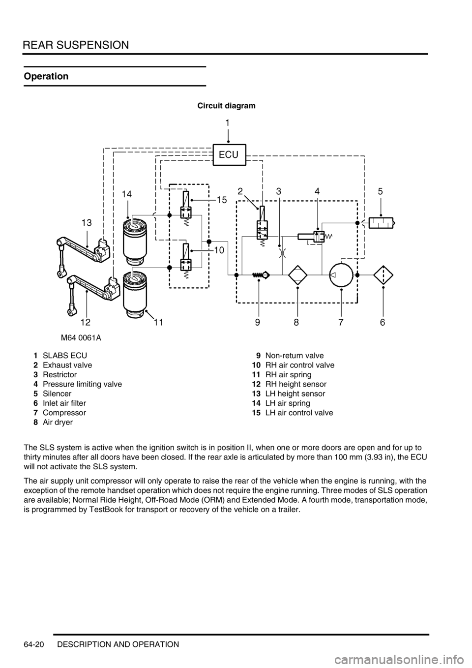
Circuit diagram
1SLABS ECU
2Exhaust valve
3Restrictor
4Pressure limiting valve
5Silencer
6Inlet air filter
7Compressor
8Air dryer9Non-return valve
10RH air control valve
11RH air spring
12RH height sensor
13LH height sensor
14LH air spring
15LH air control valve
The SLS system is active when the ignition switch is in position II, when one or more doors are open and for up to
thirty minutes after all doors have been closed. If the rear axle is articulated by more than 100 mm (3.93 in), the ECU
will not activate the SLS system.
The air supply unit compressor will only operate to raise the rear of the vehicle when the engine is running, with the
exception of the remote handset operation which does not require the engine running. Three modes of SLS operation
are available; Normal Ride Height, Off-Road Mode (ORM) and Extended Mode. A fourth mode, transportation mode,
is programmed by TestBook for transport or recovery of the vehicle on a trailer.