Page 629 of 1672

MANIFOLDS AND EXHAUST SYSTEMS - TD5
30-1-8 REPAIRS
Gasket - exhaust manifold
$% 30.15.12
Remove
Note: The following procedure covers engines
fitted with or without an EGR cooler. The EGR
cooler is bolted to the front of the cylinder head.
1.Remove turbocharger.
+ ENGINE MANAGEMENT SYSTEM -
Td5, REPAIRS, Turbocharger.
2. Models with air conditioning: Remove
auxiliary drive belt.
+ CHARGING AND STARTING,
REPAIRS, Belt - auxiliary drive.
3. Models with air conditioning: Remove 4 bolts
securing compressor and move to one side.
4.Remove and discard 2 Allen screws securing
EGR pipe to exhaust manifold.
Note: Engine with EGR cooler illustrated.5.Remove 10 nuts securing exhaust manifold to
cylinder head.
6.Remove exhaust manifold and gasket.
Refit
1.Clean exhaust manifold and mating faces.
2.Fit new gasket.Fit exhaust manifold and,
working from the centre outwards, tighten nuts
to 25 Nm (18 lbf.ft) .
3. Models with air conditioning:
Positioncompressor and tighten bolts to 25 Nm
(18 lbf.ft).
4.Position EGR valve pipe, fit new Allen screws
and tighten to 9 Nm (7 lbf.ft).
5.Fit turbocharger.
+ ENGINE MANAGEMENT SYSTEM -
Td5, REPAIRS, Turbocharger.
6. Models with air conditioning: Fit auxiliary
drive belt.
+ CHARGING AND STARTING,
REPAIRS, Belt - auxiliary drive.
Page 659 of 1672

CLUTCH - TD5
33-1-8 DESCRIPTION AND OPERATION
The dual mass flywheel is used to insulate the gearbox from torsional and transient vibrations produced by the engine.
The flywheel comprises primary and secondary flywheels with the drive between the two transferred by a torsional
damper which comprises four coil springs. The springs are located in the inside diameter of the primary flywheel. Two
of the springs are of smaller diameter and fit inside the larger diameter springs.
The primary flywheel locates the ring gear and is attached to the crankshaft flange with eight bolts. The two pairs of
coil springs are located in a recess in the flywheel between two riveted retainers. A roller bearing is pressed onto the
central boss of the primary flywheel and retained with a riveted plate. The bearing provides the mounting for the
secondary flywheel.
The secondary flywheel comprises two parts; an outer flywheel which provides the friction surface for the clutch drive
plate and an inner drive plate which transfers the drive from the primary flywheel, via the coil springs, to the outer
flywheel. The two components of the secondary flywheel are secured to each other with rivets. The inner drive plate
is located between the two pairs of coil springs and can rotate on the ball bearing in either direction against the
combined compression force of the four coil springs. Under high torque loading conditions the secondary flywheel can
rotate in either direction up to 70
° in relation to the primary flywheel.
The operating face of the secondary flywheel is machined to provide a smooth surface for the drive plate to engage
on. Three dowels and six studs and nuts provide for the location and attachment of the pressure plate.
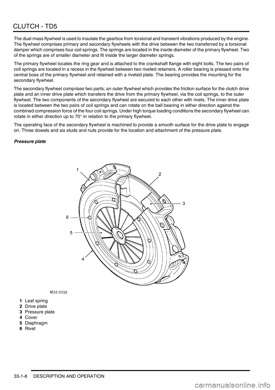
Pressure plate
1Leaf spring
2Drive plate
3Pressure plate
4Cover
5Diaphragm
6Rivet
Page 676 of 1672

CLUTCH - V8
DESCRIPTION AND OPERATION 33-2-9
The drive plate is of the spring centred type and is sandwiched between the pressure plate and the flywheel. The drive
plate has a splined hub which engages with the splines on the primary drive shaft from the gearbox. The hub is located
in an inner plate which contains six compression damper springs. A spring retainer plate and a disc adaptor are
secured together with stop pins which limit the angular deflection of the disc adaptor. Engine power is transmitted from
the disc adaptor to the damper springs. The damper springs then transfer the power to the retainer plate and the hub.
Friction washers are located between the hub, retainer plate and disc adaptor and provide further damping.
A spring steel plate is riveted to the disc adaptor and provides the attachment surface for the drive plate friction
material. The friction material comprises discs which are secured with rivets to each side of the plate. The rivets are
installed through recessed holes in the disc and emerge in recessed holes in the opposite disc. The drive plate is 267
mm (10.5 in) diameter and has a friction material manufactured from APTEC T385.
Page 776 of 1672

TRANSFER BOX - LT230SE
OVERHAUL 41-43
4.Remove 3 bolts securing differential lock
selector housing and remove housing.
5.Remove and discard 'O' ring from selector
housing.
6.Remove Allen plug and remove detent spring
and ball.
7.Remove differential lock warning lamp switch
and locknut.
Note: Locknut is only fitted to switches up to 03
MY, a modified switch and sealing washer is
fitted from 03 MY onwards.
8.03 MY onwards: Remove differential lock
warning lamp switch from end of front output
shaft housing, discard sealing washer.
9.Compress differential lock selector fork spring
and remove retaining clips from each end of
spring.
10.Withdraw differential lock selector shaft from
front output housing, recover spring and
remove selector fork.
Note: Carry out the following operations for all
transfer boxes.11.Position tool LRT-51-003 to output shaft drive
flange, remove and discard nut, steel and felt
washers; remove output shaft drive flange.
12.Using a copper mallet, drive output shaft from
housing, recover bearing spacer.
13. If fitted: Noting its fitted position, remove dog
clutch from output shaft.
Page 781 of 1672

TRANSFER BOX - LT230SE
41-48 OVERHAUL
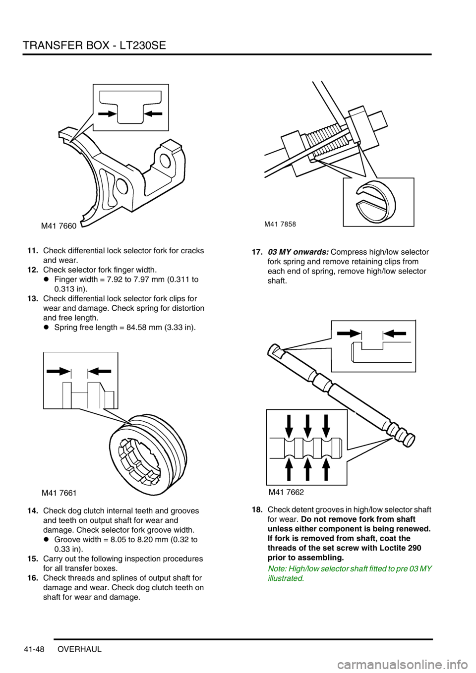
11.Check differential lock selector fork for cracks
and wear.
12.Check selector fork finger width.
lFinger width = 7.92 to 7.97 mm (0.311 to
0.313 in).
13.Check differential lock selector fork clips for
wear and damage. Check spring for distortion
and free length.
lSpring free length = 84.58 mm (3.33 in).
14.Check dog clutch internal teeth and grooves
and teeth on output shaft for wear and
damage. Check selector fork groove width.
lGroove width = 8.05 to 8.20 mm (0.32 to
0.33 in).
15.Carry out the following inspection procedures
for all transfer boxes.
16.Check threads and splines of output shaft for
damage and wear. Check dog clutch teeth on
shaft for wear and damage.17.03 MY onwards: Compress high/low selector
fork spring and remove retaining clips from
each end of spring, remove high/low selector
shaft.
18.Check detent grooves in high/low selector shaft
for wear. Do not remove fork from shaft
unless either component is being renewed.
If fork is removed from shaft, coat the
threads of the set screw with Loctite 290
prior to assembling.
Note: High/low selector shaft fitted to pre 03 MY
illustrated.
Page 788 of 1672

TRANSFER BOX - LT230SE
OVERHAUL 41-55
37.Heat the front output housing to 100°C (210°F)
and fit new output shaft bearing using tool
LRT-41-011.
38.Allow housing to air cool.
39.Fit new bearing retaining circlip ensuring that
circlip is fully seated.
40.Using tool LRT-41-012, fit new output shaft oil
seal. Check that oil seal is just contacting
circlip. 41.Position selected shim in front output housing
and using tool LRT-54-003, fit new differential
front bearing track.
42.Fit bearing spacer to output shaft with chamfer
on spacer towards threaded end.
43. If fitted: Fit dog clutch with flange on clutch
facing towards splined end.
44.Using a copper mallet, drive output shaft into
bearing.
Note: Carry out the following operations for
transfer boxes fitted with differential lock.
45.Compress differential lock selector spring and
fit selector fork.
46.Position selector fork to groove in dog clutch.
47.Fit selector shaft and locate in housing recess,
rotate shaft until the two flats for retaining clips
are at right angles to the cover plate mating
face.
Page 789 of 1672

TRANSFER BOX - LT230SE
41-56 OVERHAUL
48.Compress selector spring and fit retaining clips
at each end of spring.
CAUTION: Ensure ends of spring are fully
seated in recess of clips.
49.Fit detent ball and spring.
50.Apply Loctite 290 to threads of detent plug.
51.Fit and tighten detent plug, then loosen 2
complete turns.
52.Fit new 'O' ring to differential lock selector
housing.
53.Fit selector housing, ensure selector finger is
located in shaft recess.
54.Apply Loctite 290 to threads of bolts, and
tighten selector housing bolts to 25 Nm (18
lbf.ft).
55.Clean threads of differential lock warning lamp
switch(es).
56.Up to 03 MY: Fit nut to switch head with
counterbore positioned towards switch head.
The nut acts as a spacer to ensure that
switch setting is correct. Always ensure
that nut is fully tightened to switch head (no
gap).
57.Apply Hylomar PL 32 sealant to threads of
differential warning lamp switch(es).
58.Up to 03 MY: Position switch into front output
housing until nut bottoms out on housing;
tighten nut to 11 Nm (8 lbf.ft)
59.03 MY onwards: Fit new sealing washers to
switches, fit switches in front output housing
and tighten to 25Nm (18 lbf.ft).
Note: Carry out the following operations for all
transfer boxes.
60.Apply sealant, Part No. STC 3254 to front
output shaft housing. 61.Position housing ensuring that output shaft and
dog clutch splines - if fitted are correctly
engaged.
62.Clean output housing bolt threads.
63.Apply Loctite 290 to threads of bolts.
64.Fit output shaft housing bolts and tighten in a
diagonal sequence to 45 Nm (33 lbf.ft).
65.Fit output flange, new felt washer, steel washer
and new retaining nut.
66.Using tool LRT-51-003 to restrain flange,
tighten output flange nut to 162 Nm (119 lbf.ft).
67. If fitted - Operate differential lock selector
lever and check that detent ball can be felt to
positively engage/disengage with grooves in
shaft. Screw plug in or out until setting is
correct.
68.Fit high/low selector shaft detent ball and
spring.
69.Apply Loctite 290 sealant to threads of high/low
selector shaft detent plug.
70.Fit and tighten plug, then loosen 2 complete
turns.
71. Operate high/low selector lever and check that
detent ball can be felt to positively engage/
disengage with grooves in shaft. Screw plug in
or out until setting is correct.
72.Fit intermediate gear cluster.
+ TRANSFER BOX - LT230SE,
OVERHAUL, Intermediate gear assembly.
Page 790 of 1672

TRANSFER BOX - LT230SE
OVERHAUL 41-57
Dog clutch - differential lock
$% 41.20.23
Disassembly
1.Remove 6 bolts securing high/low cross shaft
housing to front output shaft housing and
remove housing.
2.Note position of longest bolt and remove 8
bolts securing front output shaft housing to
main casing and remove housing.
3.Remove 3 bolts securing differential lock
selector housing and remove housing. 4.Remove and discard 'O' ring from selector
housing.
5.Remove differential warning lamp switch and
locknut.
Note: Locknut is only fitted to switches up to 03
MY, a modified switch and sealing washer is
fitted from 03 MY onwards..
6.03 MY onwards: Remove differential lock
warning lamp switch from end of front output
shaft housing, discard sealing washer.
7.Remove Allen plug and remove detent spring
and ball.
8.Compress differential lock selector fork spring
and remove retaining clips from each end of
spring.
9.Withdraw differential lock selector shaft from
front output housing, recover spring and
remove selector fork.