2002 LAND ROVER DISCOVERY ac compre
[x] Cancel search: ac comprePage 1391 of 1672

AIR CONDITIONING
82-18DESCRIPTION AND OPERATION
Operation
General
While the system is on, the ATC ECU operates the refrigerant system and the inlet air, blower speed, air temperature
and air distribution functions to produce the conditions requested on the control panel. When the system is first
switched on, the ATC ECU resumes the control outputs in use when the system was last switched off. If conditions
have changed, or a different mode is selected to switch the system on, the control outputs are then changed to
produce the required new settings.
The system operates in automatic, economy and defrost modes, with manual overrides of the inlet air source, blower
speed and air distribution. The air temperature is automatically controlled in all operating modes.
In the automatic mode, the ATC ECU operates the system to warm-up or cool down the cabin to establish and
maintain the temperature selections on the control panel, while directing the air to those outlets most comfortable for
the occupant(s). If a difference between the LH and RH temperature selections causes a conflict of the required inlet
air source, blower speed or air distribution settings, priority is given to achieving the temperature requested on the
driver's side of the control panel.
The ATC ECU enters the economy mode when the refrigerant compressor is selected off while the system is in the
automatic mode, which reduces the load on the engine. Economy mode operation is similar to the automatic mode,
but without the ability to cool the cabin if the ambient temperature is higher than the temperature selections made on
the control panel, or to dehumidify the air in the cabin.
In the defrost mode, the ATC ECU sets the inlet air source to fresh air, the blower to maximum speed, the air
distribution to windscreen and side windows, and outputs signals to the BCU to operate the rear window heater and
(where fitted) the windscreen heater. The BCU starts or, if the heaters are already on, resets the heater timers and
energises the rear window and windscreen heaters for a complete on cycle.
Air temperature control
To determine the amount of heat or cooling required by the cabin, the ATC ECU uses the sensor inputs and the
temperatures selected on the control panel to calculate target air outlet temperatures for the driver's and the front
passenger's side of the heater assembly. The ATC ECU then signals the servo motors controlling the respective blend
flaps in the heater assembly to move to the flaps to the appropriate position. The target temperatures are constantly
updated and, in the automatic mode, also used in further calculations to determine the inlet air source, the blower
speed and the air distribution.
Inlet air control
The inlet air source is automatically controlled while the system is off or on. While the system is on, the inlet air source
can also be manually controlled to give timed recirculated air or latched recirculated air.
While the system is off, the ATC ECU uses vehicle speed to determine the inlet air source. With the vehicle at rest,
the inlet air source is set to recirculated air. When vehicle speed reaches 17.5 mph (28 km/h), the inlet air source
changes to fresh air. The inlet air source then remains at fresh air until the vehicle speed decreases to 5 mph (8 km/
h), when it returns to recirculated air.
While the system is on, the ATC ECU uses the LH and RH temperature selections, vehicle speed, ambient air
temperature and coolant temperature to determine the inlet air source. In the automatic mode:
lIf one temperature selection is set to LO and one is set to a specific temperature or HI, the inlet air is set to
recirculated air.
lIf one temperature selection is set to HI and one is set to a specific temperature or HI, the inlet air is set to fresh
air.
lWhen specific LH and RH temperature selections are set, the inlet air source remains at fresh air except when
the air distribution function is set to face level only or face level and footwell outlets. If the air distribution function
is set to face level only or face level and footwell outlets, at 56 mph (90 km/h) the inlet air source changes to
recirculated air (to exclude ram effect, which becomes excessive at speed). When the vehicle speed decreases
to 37.5 mph (60 km/h), the inlet air source returns to fresh air.
Page 1393 of 1672

AIR CONDITIONING
82-20DESCRIPTION AND OPERATION
Air distribution control
To control the air distribution within the cabin the ATC ECU signals the servo motor controlling the distribution flaps
in the heater assembly to move to the flaps to the appropriate position.
In the automatic and economy modes, if the LH or RH temperature selections are set to LO or HI, air distribution is
fixed as follows:
lIf one is set to LO and one is set to a specific temperature, to face level only.
lIf one is set to HI and one is set to a specific temperature, to footwells only.
lIf one is set to LO and one is set to HI, to face level and footwells.
When specific LH and RH temperature selections are set, air distribution is determined from the target air outlet
temperatures. For higher target air outlet temperatures, air distribution is set to footwells only. For lower target air
outlet temperatures, air distribution is set to face level only. For intermediate target air outlet temperatures, air
distribution is set to face level and footwells. When the air distribution is set to face level and footwells, the ATC ECU
varies the bias between the footwells and the face level outlets, in three stages, to provide a gradual transition of air
distribution from footwells only to face level only. The three stages of bias are also employed when the air distribution
is manually selected to face level and footwells.
During warm-up, the air distribution changes to face level and footwells for a period, then reverts to footwells only.
The period of air distribution at face level and footwells can be cancelled by pressing and holding the on/off and defrost
mode switches, then turning the ignition switch from off to on. Pressing and holding the AUTO and defrost switches,
then turning the ignition switch from off to on, restores the period of air distribution at face level and footwells.
Compressor control
To engage the compressor clutch, the ATC ECU outputs a compressor clutch request to the ECM, which then
energises the A/C compressor clutch relay. Compressor operation is governed by the evaporator outlet air
temperature, at one of two settings, dependent on the amount of cooling required. When more cooling is required, the
compressor clutch request is output if evaporator outlet air temperature increases to 4
°C (39 °F) and cancelled when
it decreases to 3
°C (37 °F). When less cooling is required, the compressor clutch request is output if evaporator outlet
air temperature increases to 11
°C (52 °F) and cancelled when it decreases to 10 °C (50 °F).
Engine cooling fan control
While the A/C system is on, operation of the electric engine cooling fan, to assist refrigerant condenser operation, is
determined by a combination of vehicle speed and external air temperature. When cooling fan operation is required,
the ATC ECU outputs a cooling fan request to the ECM, which then energises the cooling fan relay. The cooling fan
request is output if vehicle speed is 80 km/h or less while the external air temperature is 28
°C (82 °F) or more. The
request is cancelled, and the cooling fan switched off, if either the vehicle speed increases to 100 km/h, or the external
air temperature decreases to 25
°C (77 °F).
Default settings
If the battery power supply to the ATC ECU is disrupted for any reason, e.g. battery disconnected, the system reverts
to default settings when the battery power supply is restored. Default settings are:
lTemperature indications in
°C (in some markets a conversion connector is fitted to the ATC ECU to change the
default temperature scale to
°F).
lLH and RH outlet temperatures of 22
°C (72 °F).
laudible warning switched on.
lWarm-up air distribution (to face level and footwells) function switched on.
lIf the system is first switched on using the A/C on/off switch, the automatic mode is engaged, regardless of the
settings in use when the battery was disconnected.
Page 1404 of 1672
AIR CONDITIONING
REPAIRS 82-31
REPAIRS
Compressor - diesel
$% 82.10.20
Remove
1.Remove engine acoustic cover.
2.Depressurise air conditioning system.
+ AIR CONDITIONING, REFRIGERANT
RECOVERY, RECYCLING AND
RECHARGING, Refrigerant recovery,
recycling and recharging.
3.Remove auxiliary drive belt.
+ CHARGING AND STARTING,
REPAIRS, Belt - auxiliary drive.
4.Drain cooling system.
+ COOLING SYSTEM - Td5,
ADJUSTMENTS, Drain and refill.
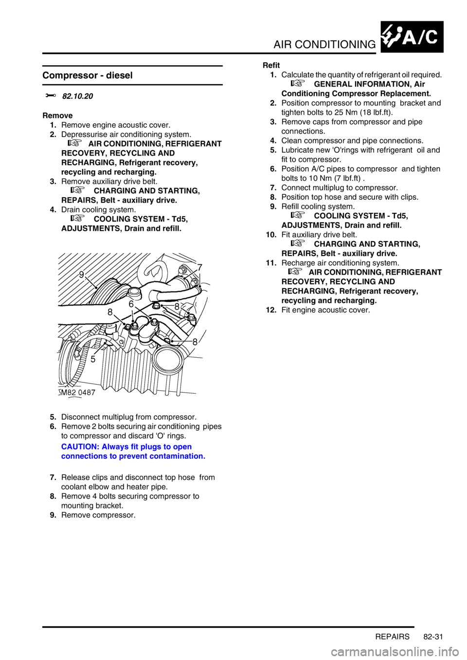
5.Disconnect multiplug from compressor.
6.Remove 2 bolts securing air conditioning pipes
to compressor and discard 'O' rings.
CAUTION: Always fit plugs to open
connections to prevent contamination.
7.Release clips and disconnect top hose from
coolant elbow and heater pipe.
8.Remove 4 bolts securing compressor to
mounting bracket.
9.Remove compressor.Refit
1.Calculate the quantity of refrigerant oil required.
+ GENERAL INFORMATION, Air
Conditioning Compressor Replacement.
2.Position compressor to mounting bracket and
tighten bolts to 25 Nm (18 lbf.ft).
3.Remove caps from compressor and pipe
connections.
4.Clean compressor and pipe connections.
5.Lubricate new 'O'rings with refrigerant oil and
fit to compressor.
6.Position A/C pipes to compressor and tighten
bolts to 10 Nm (7 lbf.ft) .
7.Connect multiplug to compressor.
8.Position top hose and secure with clips.
9.Refill cooling system.
+ COOLING SYSTEM - Td5,
ADJUSTMENTS, Drain and refill.
10.Fit auxiliary drive belt.
+ CHARGING AND STARTING,
REPAIRS, Belt - auxiliary drive.
11.Recharge air conditioning system.
+ AIR CONDITIONING, REFRIGERANT
RECOVERY, RECYCLING AND
RECHARGING, Refrigerant recovery,
recycling and recharging.
12.Fit engine acoustic cover.
Page 1405 of 1672
AIR CONDITIONING
82-32REPAIRS
Compressor - V8
$% 82.10.20
Remove
1.Depressurise air conditioning system.
+ AIR CONDITIONING, REFRIGERANT
RECOVERY, RECYCLING AND
RECHARGING, Refrigerant recovery,
recycling and recharging.
2.Remove auxiliary drive belt.
+ CHARGING AND STARTING,
REPAIRS, Belt - auxiliary drive.
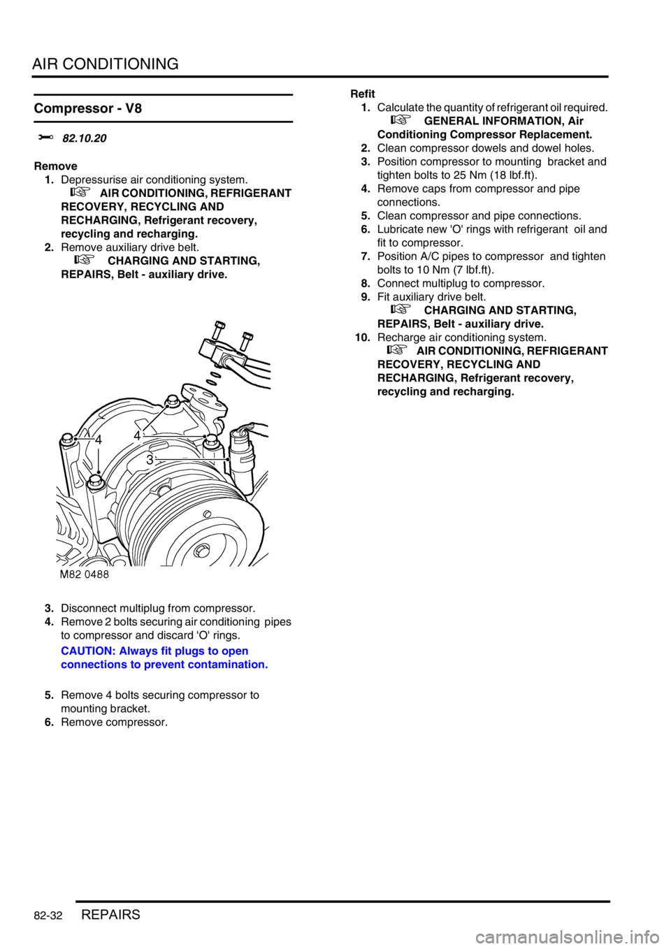
3.Disconnect multiplug from compressor.
4.Remove 2 bolts securing air conditioning pipes
to compressor and discard 'O' rings.
CAUTION: Always fit plugs to open
connections to prevent contamination.
5.Remove 4 bolts securing compressor to
mounting bracket.
6.Remove compressor.Refit
1.Calculate the quantity of refrigerant oil required.
+ GENERAL INFORMATION, Air
Conditioning Compressor Replacement.
2.Clean compressor dowels and dowel holes.
3.Position compressor to mounting bracket and
tighten bolts to 25 Nm (18 lbf.ft).
4.Remove caps from compressor and pipe
connections.
5.Clean compressor and pipe connections.
6.Lubricate new 'O' rings with refrigerant oil and
fit to compressor.
7.Position A/C pipes to compressor and tighten
bolts to 10 Nm (7 lbf.ft).
8.Connect multiplug to compressor.
9.Fit auxiliary drive belt.
+ CHARGING AND STARTING,
REPAIRS, Belt - auxiliary drive.
10.Recharge air conditioning system.
+ AIR CONDITIONING, REFRIGERANT
RECOVERY, RECYCLING AND
RECHARGING, Refrigerant recovery,
recycling and recharging.
Page 1580 of 1672
HARNESSES
REPAIRS 86-7-9
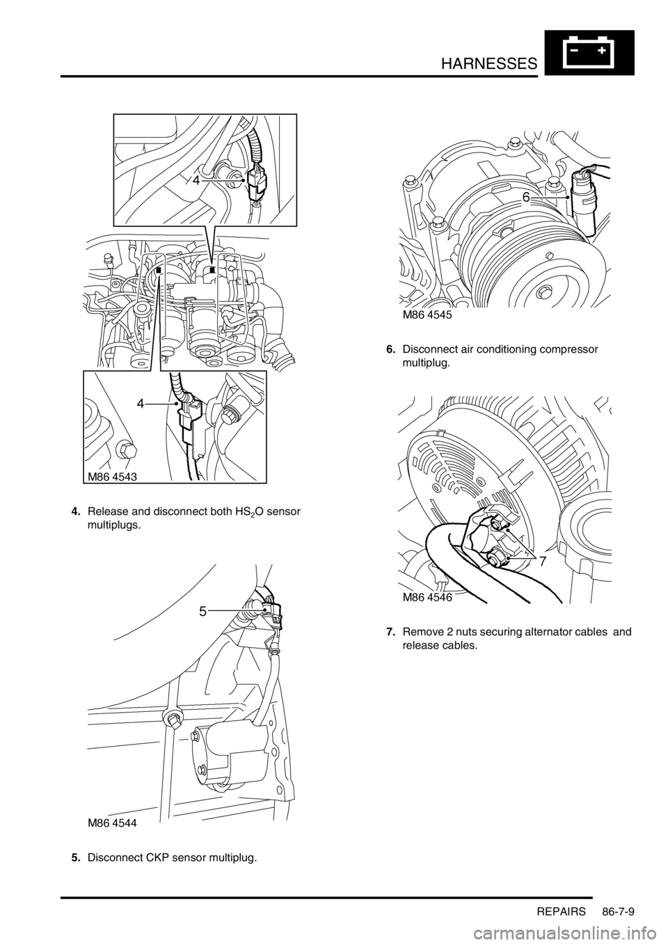
4.Release and disconnect both HS2O sensor
multiplugs.
5.Disconnect CKP sensor multiplug. 6.Disconnect air conditioning compressor
multiplug.
7.Remove 2 nuts securing alternator cables and
release cables.
Page 1583 of 1672

HARNESSES
86-7-12 REPAIRS
24.Remove bolt securing harness clip to LH side of
engine.
25.Disconnect camshaft sensor and oil pressure
switch multiplugs.
26.Remove engine harness. Refit
1.Position engine harness around engine.
2.Connect oil pressure switch and camshaft
sensor multiplugs.
3.Fit and tighten bolt securing harness to LH side
of engine.
4.Connect both knock sensor multiplugs.
5.Connect battery cable and solenoid cable to
starter motor.
6.Position starter heat shield and secure with
bolt.
7.Clean exhaust flange mating faces, using a
new gasket align exhaust fit nuts and tighten to
60 Nm (44 lbf.ft).
8.Remove stand(s) and lower vehicle.
9.Position harness into footwell and secure
grommet.
10.Connect ECM multiplugs.
11.Position toe board and secure with trim fixings.
12.Connect engine harness to main harness
multiplug and secure earth lead.
13.Connect EVAP solenoid multiplug.
14.Connect both fuse box multiplugs.
15.Position starter lead to fuse box and secure
screw.
16.Fit fuse box cover.
17.Position battery positive lead to battery and
secure nut.
18.Secure harness to coolant rail.
19.Position alternator cables and tighten terminal
B+ to 18 Nm (13 lbf.ft) and terminal D+ to 5 Nm
(3.7 lbf.ft)
20.Connect coolant temperature sensor multiplug.
21.Connect A/C compressor multiplug.
22.Secure harness clip to rear of LH cylinder head.
23.Connect CKP sensor multiplug.
24.Secure injector harness and connect injector
multiplugs.
25.Connect coil multiplugs.
26.Connect and secure HS
2O sensor multiplug
27.Fit upper inlet manifold.
+ MANIFOLDS AND EXHAUST
SYSTEMS - V8, REPAIRS, Gasket - inlet
manifold - upper - Without Secondary Air
Injection.
28.Connect battery earth lead.
Page 1586 of 1672
HARNESSES
REPAIRS 86-7-15
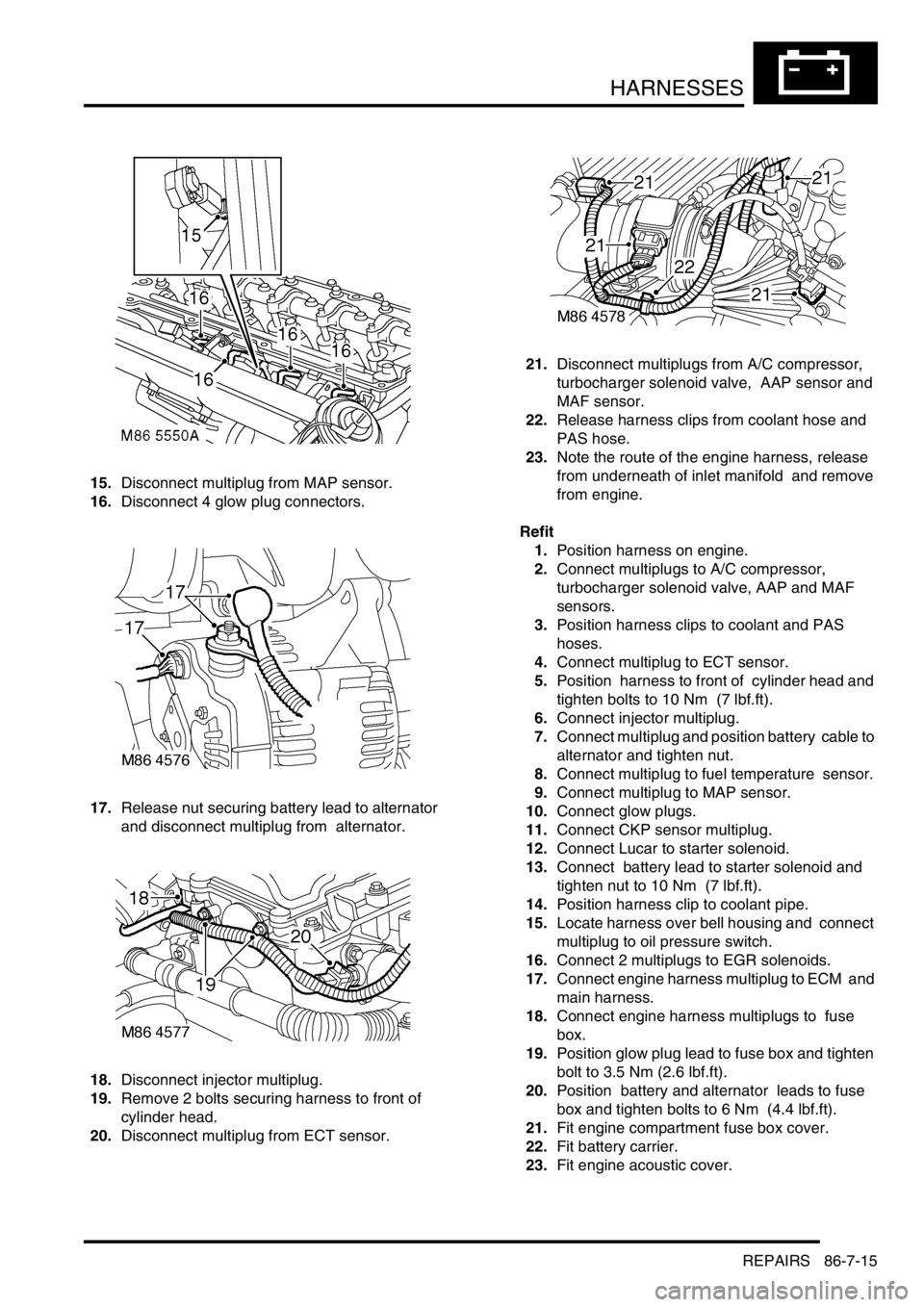
15.Disconnect multiplug from MAP sensor.
16.Disconnect 4 glow plug connectors.
17.Release nut securing battery lead to alternator
and disconnect multiplug from alternator.
18.Disconnect injector multiplug.
19.Remove 2 bolts securing harness to front of
cylinder head.
20.Disconnect multiplug from ECT sensor. 21.Disconnect multiplugs from A/C compressor,
turbocharger solenoid valve, AAP sensor and
MAF sensor.
22.Release harness clips from coolant hose and
PAS hose.
23.Note the route of the engine harness, release
from underneath of inlet manifold and remove
from engine.
Refit
1.Position harness on engine.
2.Connect multiplugs to A/C compressor,
turbocharger solenoid valve, AAP and MAF
sensors.
3.Position harness clips to coolant and PAS
hoses.
4.Connect multiplug to ECT sensor.
5.Position harness to front of cylinder head and
tighten bolts to 10 Nm (7 lbf.ft).
6.Connect injector multiplug.
7.Connect multiplug and position battery cable to
alternator and tighten nut.
8.Connect multiplug to fuel temperature sensor.
9.Connect multiplug to MAP sensor.
10.Connect glow plugs.
11.Connect CKP sensor multiplug.
12.Connect Lucar to starter solenoid.
13.Connect battery lead to starter solenoid and
tighten nut to 10 Nm (7 lbf.ft).
14.Position harness clip to coolant pipe.
15.Locate harness over bell housing and connect
multiplug to oil pressure switch.
16.Connect 2 multiplugs to EGR solenoids.
17.Connect engine harness multiplug to ECM and
main harness.
18.Connect engine harness multiplugs to fuse
box.
19.Position glow plug lead to fuse box and tighten
bolt to 3.5 Nm (2.6 lbf.ft).
20.Position battery and alternator leads to fuse
box and tighten bolts to 6 Nm (4.4 lbf.ft).
21.Fit engine compartment fuse box cover.
22.Fit battery carrier.
23.Fit engine acoustic cover.
Page 1606 of 1672
DRIVING AIDS
DESCRIPTION AND OPERATION 86-8-7
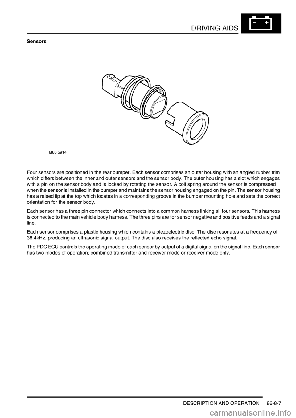
Sensors
Four sensors are positioned in the rear bumper. Each sensor comprises an outer housing with an angled rubber trim
which differs between the inner and outer sensors and the sensor body. The outer housing has a slot which engages
with a pin on the sensor body and is locked by rotating the sensor. A coil spring around the sensor is compressed
when the sensor is installed in the bumper and maintains the sensor housing engaged on the pin. The sensor housing
has a raised lip at the top which locates in a corresponding groove in the bumper mounting hole and sets the correct
orientation for the sensor body.
Each sensor has a three pin connector which connects into a common harness linking all four sensors. This harness
is connected to the main vehicle body harness. The three pins are for sensor negative and positive feeds and a signal
line.
Each sensor comprises a plastic housing which contains a piezoelectric disc. The disc resonates at a frequency of
38.4kHz, producing an ultrasonic signal output. The disc also receives the reflected echo signal.
The PDC ECU controls the operating mode of each sensor by output of a digital signal on the signal line. Each sensor
has two modes of operation; combined transmitter and receiver mode or receiver mode only.