2002 LAND ROVER DISCOVERY ac compre
[x] Cancel search: ac comprePage 1339 of 1672

CORROSION PREVENTION AND SEALING
77-4-24 SEALING
Water leaks
Where water leakage is involved, always adopt a logical approach to the problem using a combination of skill,
experience and intuition. Do not reach a conclusion based only on visual evidence, such as assuming that a wet
footwell is caused by a leak emanating from the windscreen. It will often be found that the source of the leak is
elsewhere. Use of the correct procedure will increase the chance of locating a leak, however obscure it may seem.
Tools and equipment
The following tools and equipment are recommended for the purpose of detection and rectification of water leaks:
1Garden sprayer (hand-operated)
2Wet/dry vacuum cleaner
3Dry, absorbent cloths
4Battery torch
5Small mirror
6Weatherstrip locating tool
7Trim panel remover
8Small wooden or plastic wedges
9Dry compressed air supply
10Hot air blower
11Sealer applicators
12Ultrasonic leak detector
During leak detection, the vehicle should be considered in three basic sections:
lThe front interior space;
lThe rear passenger space;
lThe loadspace or boot.
Testing
From the information supplied by the customer it should be possible for the bodyshop operator to locate the starting
point from which the leak may be detected. After the area of the leak has been identified, find the actual point of entry
into the vehicle.
A simple and effective means in the first instance is an ordinary garden spray with provision for pressure and jet
adjustment, which will allow water to be directed in a jet or turned into a fine spray. Use a mirror and a battery-powered
torch (NOT a mains voltage inspection lamp) to see into dark corners.
The sequence of testing is particularly important. Start at the lowest point and work slowly upwards, to avoid testing
in one area while masking the leak in another. For example, if testing started at the level of the windscreen, any water
cascading into the plenum chamber could leak through a bulkhead grommet and into the footwells. Even at this point
it could still be wrongly assumed that the windscreen seal was at fault.
Another important part of identifying a water leak is by visual examination of door aperture seals, grommets and
weatherstrips for damage, deterioration or misalignment, together with the fit of the door itself against the seals.
Sealing
When the point of the leak has been detected, it will then be necessary to rectify it using the following procedure:
1Renew all door aperture seals and weatherstrips which have suffered damage, misalignment or deterioration
2Check all body seals to ensure that they are correctly located on their mounting flanges/faces using a lipping
tool if necessary
3Dry out body seams to be treated using compressed air and/or a hot air blower as necessary
4Apply sealant on the outside of the joint wherever possible to ensure the exclusion of water
5When rectifying leaks between a screen glass and it's weatherstrip (or in the case of direct glazing, between the
glass and bodywork), avoid removing the glass if possible. Apply the approved material at the appropriate
location (i.e. glass to weatherstrip or glass to body)
Page 1374 of 1672

AIR CONDITIONING
DESCRIPTION AND OPERATION 82-1
AIR CONDITIONING DESCRIPTION AND OPERAT ION
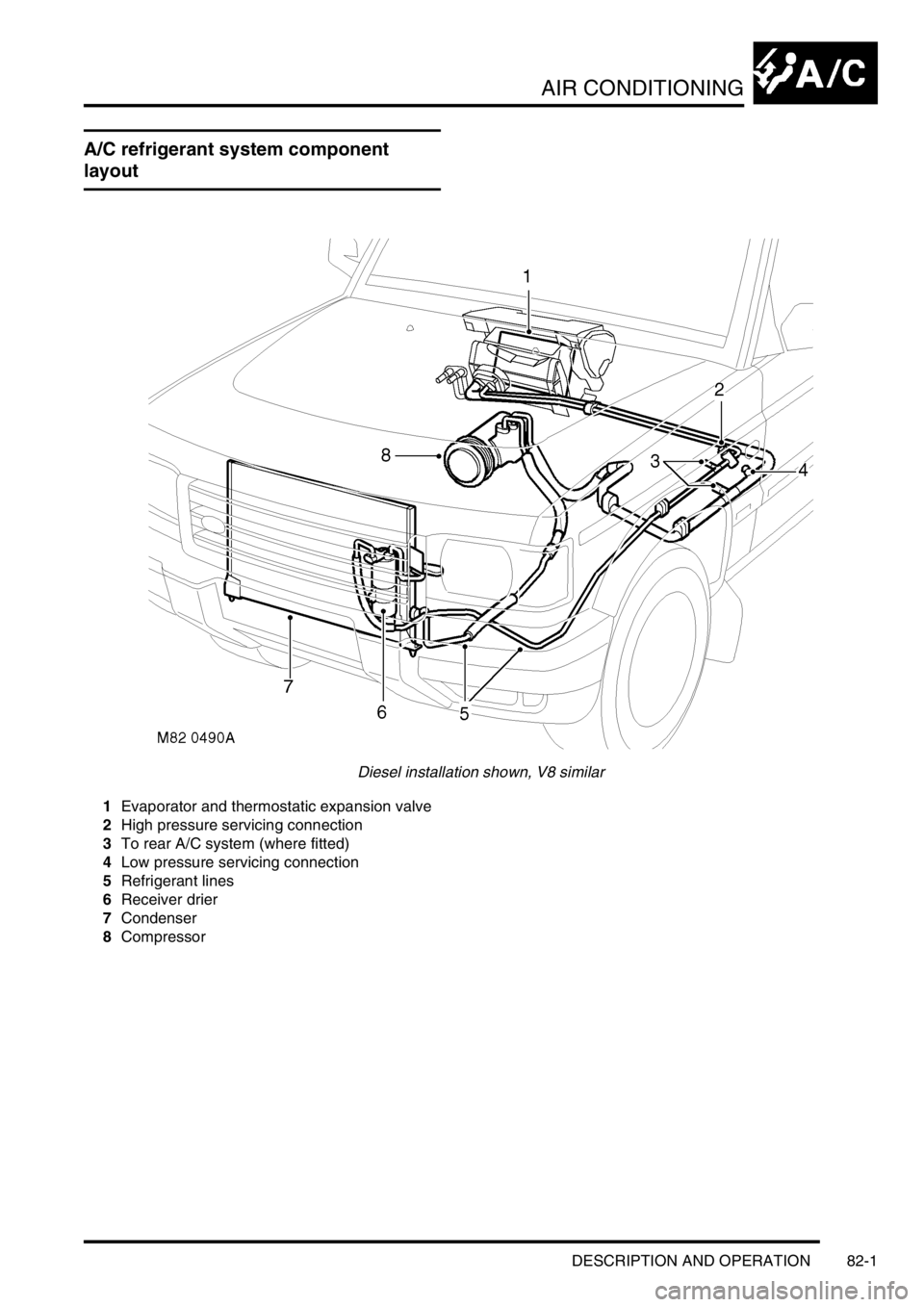
A/C refrigerant system component
layout
Diesel installation shown, V8 similar
1Evaporator and thermostatic expansion valve
2High pressure servicing connection
3To rear A/C system (where fitted)
4Low pressure servicing connection
5Refrigerant lines
6Receiver drier
7Condenser
8Compressor
Page 1377 of 1672

AIR CONDITIONING
82-4DESCRIPTION AND OPERATION
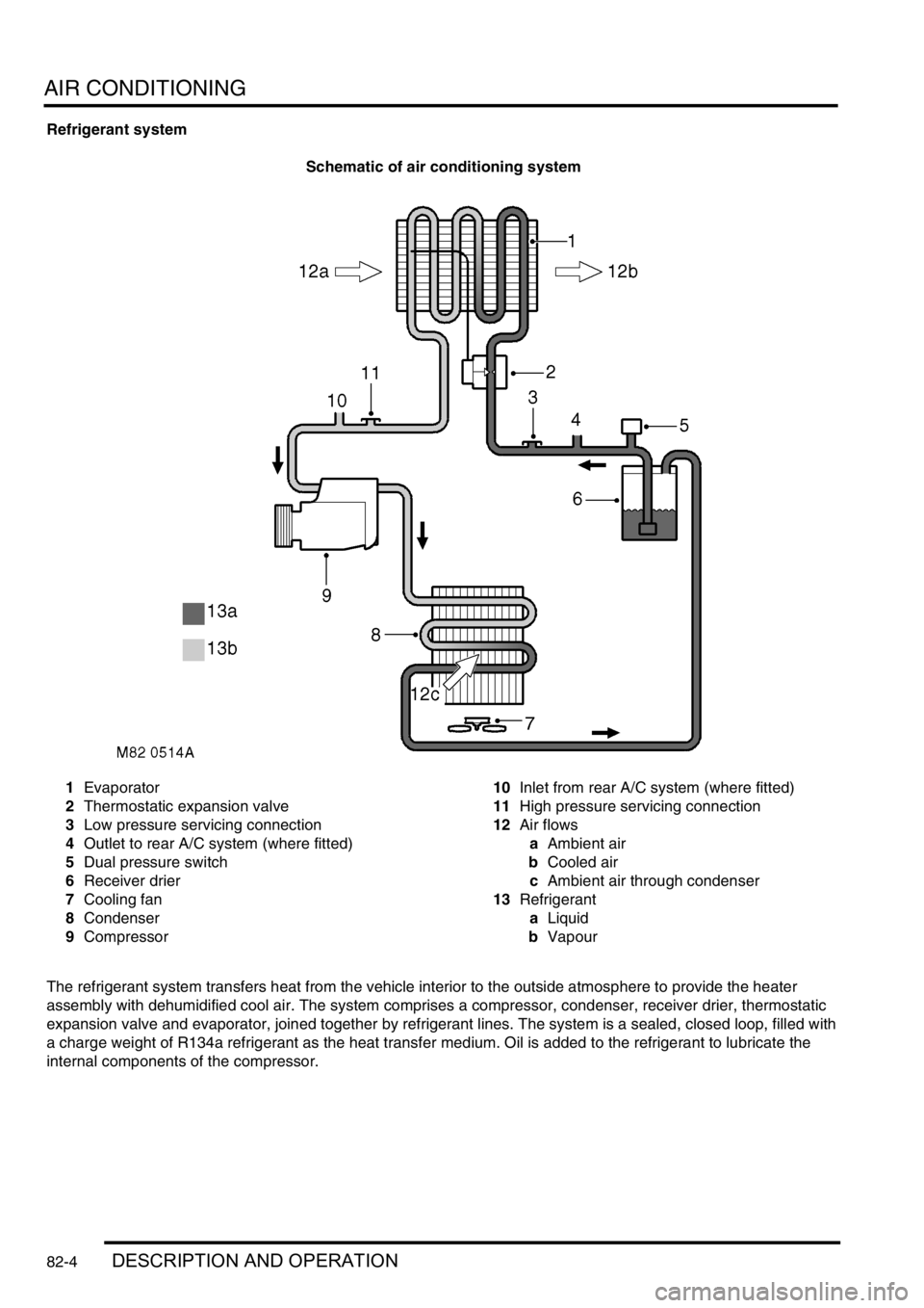
Refrigerant system
Schematic of air conditioning system
1Evaporator
2Thermostatic expansion valve
3Low pressure servicing connection
4Outlet to rear A/C system (where fitted)
5Dual pressure switch
6Receiver drier
7Cooling fan
8Condenser
9Compressor10Inlet from rear A/C system (where fitted)
11High pressure servicing connection
12Air flows
aAmbient air
bCooled air
cAmbient air through condenser
13Refrigerant
aLiquid
bVapour
The refrigerant system transfers heat from the vehicle interior to the outside atmosphere to provide the heater
assembly with dehumidified cool air. The system comprises a compressor, condenser, receiver drier, thermostatic
expansion valve and evaporator, joined together by refrigerant lines. The system is a sealed, closed loop, filled with
a charge weight of R134a refrigerant as the heat transfer medium. Oil is added to the refrigerant to lubricate the
internal components of the compressor.
Page 1378 of 1672

AIR CONDITIONING
DESCRIPTION AND OPERATION 82-5
To accomplish the transfer of heat, the refrigerant is circulated around the system, where it passes through two
pressure/temperature regimes. In each of the pressure/temperature regimes, the refrigerant changes state, during
which process maximum heat absorption or release occurs. The low pressure/temperature regime is from the
thermostatic expansion valve, through the evaporator to the compressor; the refrigerant decreases in pressure and
temperature at the thermostatic expansion valve, then changes state from liquid to vapour in the evaporator, to absorb
heat. The high pressure/temperature regime is from the compressor, through the condenser and receiver drier to the
thermostatic expansion valve; the refrigerant increases in pressure and temperature as it passes through the
compressor, then releases heat and changes state from vapour to liquid in the condenser.
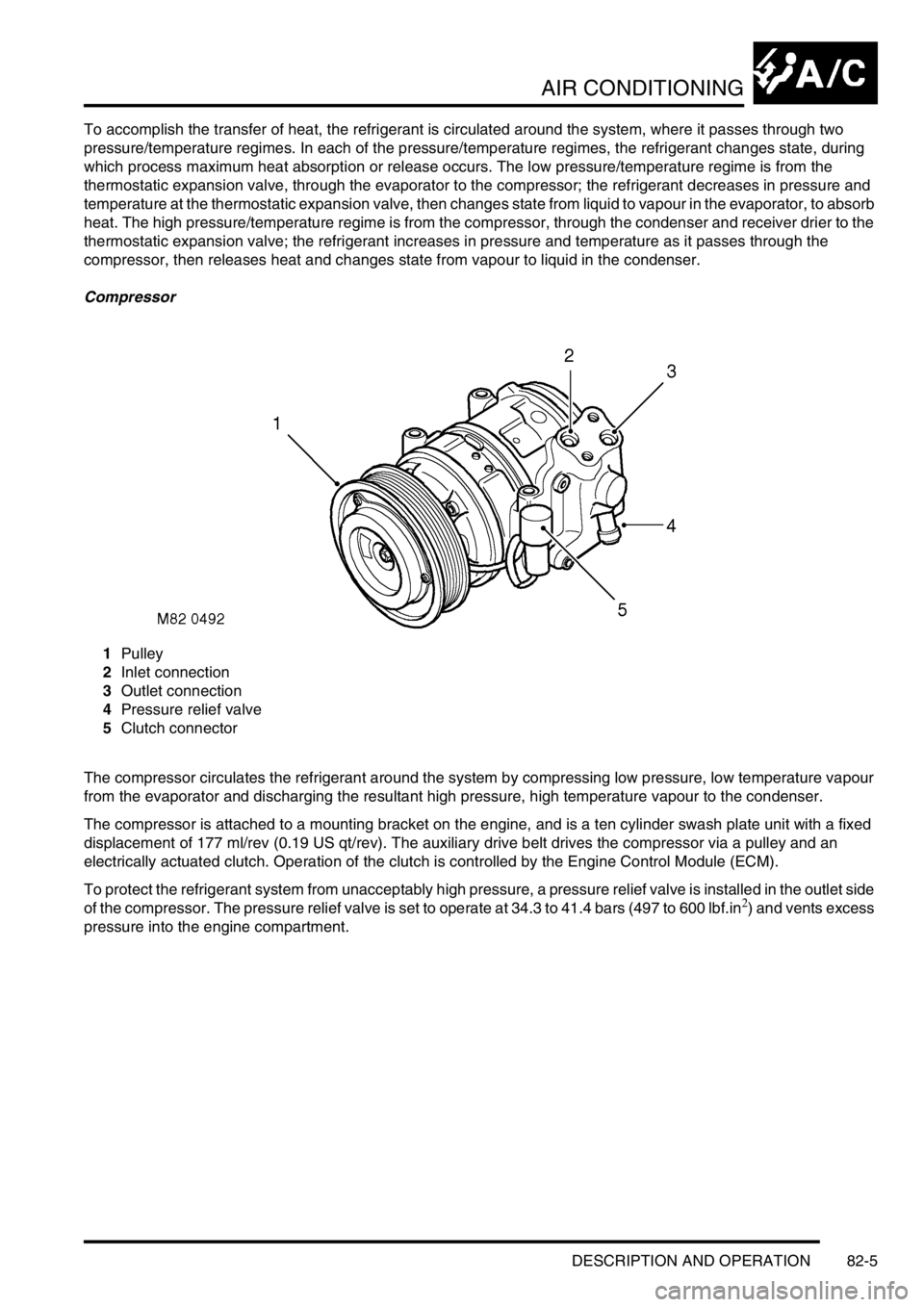
Compressor
1Pulley
2Inlet connection
3Outlet connection
4Pressure relief valve
5Clutch connector
The compressor circulates the refrigerant around the system by compressing low pressure, low temperature vapour
from the evaporator and discharging the resultant high pressure, high temperature vapour to the condenser.
The compressor is attached to a mounting bracket on the engine, and is a ten cylinder swash plate unit with a fixed
displacement of 177 ml/rev (0.19 US qt/rev). The auxiliary drive belt drives the compressor via a pulley and an
electrically actuated clutch. Operation of the clutch is controlled by the Engine Control Module (ECM).
To protect the refrigerant system from unacceptably high pressure, a pressure relief valve is installed in the outlet side
of the compressor. The pressure relief valve is set to operate at 34.3 to 41.4 bars (497 to 600 lbf.in
2) and vents excess
pressure into the engine compartment.
Page 1386 of 1672

AIR CONDITIONING
DESCRIPTION AND OPERATION 82-13
3 Hand of drive Input
4 Distribution flaps position Input
5 Heater coolant temperature Input
6 External air temperature Input
7 In-car air temperature Input
8 Blower power transistor collector voltage Input
9 Not used-
10 Not used-
11 Windscreen heater status Input
12 Rear screen heater status Input
13 Not connected -
14 Driver's blend flaps position Input
15 Passenger's blend flaps position Input
16 LH solar heating load Input
17 RH solar heating load Input
18 Evaporator Input
19 Not used-
20 Not used-
C0793
1 Blower power transistor base current Output
2 Blower relay Output
3 Windscreen heater request Output
4 Rear screen heater request Output
5 Passenger's blend flaps servo motor, drive to hot Output
6 Driver's blend flaps servo motor, drive to hot Output
7 Distribution flaps servo motor, drive to windscreen and side
windows demistOutput
8 Fresh/Recirculated air servo motor, drive to recirculated air Output
9 Cooling fan request (diesel models) Output
10 Power relay Output
11 Compressor clutch request Output
12 Cooling fan request (V8 models) Output
13 Passenger's blend flaps servo motor, drive to cold Output
14 Driver's blend flaps servo motor, drive to cold Output
15 Distribution flaps servo motor, drive to footwells Output
16 Fresh/Recirculated air servo motor, drive to fresh air Output Connector/Pin No. Description Input/Output
Page 1388 of 1672

AIR CONDITIONING
DESCRIPTION AND OPERATION 82-15
Distribution switch. Enabled only while the system is on. Provides manual control of air distribution:
lEach press changes the air distribution, in sequence, through footwells only, footwells and windscreen/side
windows demist, windscreen/side windows demist only, face level only, face level and footwells.
lIf the switch is kept depressed, after 1 second subsequent distribution changes occur every 0.4 seconds until
distribution reaches face level and footwells. Releasing and then pressing the switch again changes distribution
back to footwells only.
External air temperature (EXT) switch. Enabled while the system is on or off. Switches the external temperature output
on and off:
lIf the system is already on, the temperature output overrides the system outputs for approximately 7 seconds,
then the display reverts to system outputs.
lIf the system is switched on while the external temperature output is on, the system outputs override the external
temperature output.
Fresh/Recirculated air switch. Enabled only while the system is on. Provides manual control of inlet air selection.
Defrost mode switch. Starts the system in, or switches the system to and from, defrost mode.
Automatic mode (AUTO) switch. Starts the system in, or switches the system to and from, the automatic mode.
Economy mode (ECON) switch. Enabled only while the system is on. Provides manual on/off control of the refrigerant
system compressor, to reduce fuel consumption when there is no requirement for cool or dehumidified air, e.g. when
the ambient temperature is lower than the LH and RH temperature settings.
Temperature settings: The LH and RH temperature settings are reference inputs used by the control system and give
an approximation of the temperatures that will be established in the cabin. They are not necessarily actual distribution
outlet temperatures, or the temperatures at specific points in the cabin.
Audible warning: A 'beep' is emitted from the ATC ECU each time it receives a control switch input. This audible
warning can be switched off and on by pressing and holding the AUTO switch, then pressing and holding the A/C on/
off switch until the audible warning sounds (approximately 3 seconds). While switched off, the audible warning still
sounds when:
lSwitching between
°F and °C on the display.
lSwitching the audible warning from off to on.
lSwitching the timed feet function on and off.
lSwitching the timed recirculated inlet air on and off.
lSwitching the latched recirculated inlet air on and off.
lWhen there is a fault warning.
lRunning the self diagnostic routine.
Page 1389 of 1672

AIR CONDITIONING
82-16DESCRIPTION AND OPERATION
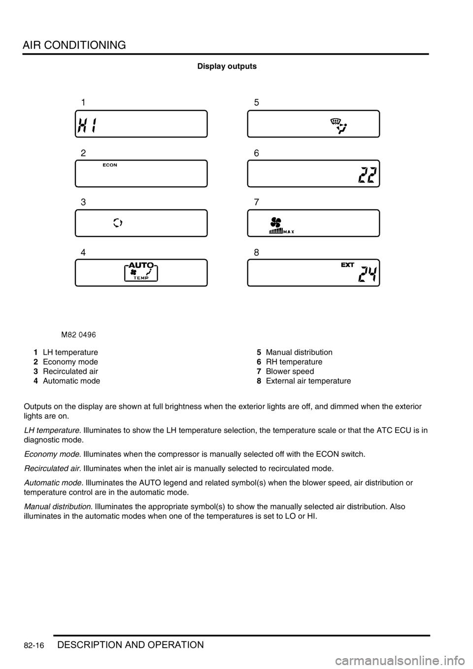
Display outputs
1LH temperature
2Economy mode
3Recirculated air
4Automatic mode5Manual distribution
6RH temperature
7Blower speed
8External air temperature
Outputs on the display are shown at full brightness when the exterior lights are off, and dimmed when the exterior
lights are on.
LH temperature. Illuminates to show the LH temperature selection, the temperature scale or that the ATC ECU is in
diagnostic mode.
Economy mode. Illuminates when the compressor is manually selected off with the ECON switch.
Recirculated air. Illuminates when the inlet air is manually selected to recirculated mode.
Automatic mode. Illuminates the AUTO legend and related symbol(s) when the blower speed, air distribution or
temperature control are in the automatic mode.
Manual distribution. Illuminates the appropriate symbol(s) to show the manually selected air distribution. Also
illuminates in the automatic modes when one of the temperatures is set to LO or HI.
Page 1390 of 1672

AIR CONDITIONING
DESCRIPTION AND OPERATION 82-17
RH temperature. Illuminates to show the RH temperature selection, external air temperature or diagnostic fault code.
Blower speed. Illuminates when the blower speed is manually selected. Also illuminates in the automatic modes when
one of the temperatures is set to LO or HI.
External air temperature. EXT illuminates to show that external air temperature is selected on.
All temperature indications on the display are in either
°C or °F. For 1 second after the system is first switched on, the
display shows only
°C or °F, in the LH temperature window, to indicate which temperature scale is in use. After 1
second, the
°C or °F indication goes off and the display shows all relevant outputs.
Temperature conversion: While the system is on, the temperature indications on the display can be switched between
the two scales by pressing and holding the fresh/recirculated air switch, then pressing and holding the A/C on/off
switch until the audible warning sounds (approximately 3 seconds).
Dual pressure switch
The dual pressure switch protects the refrigerant system from extremes of pressure. The normally closed switch is
installed in the top of the receiver drier. If minimum or maximum pressure limits are exceeded the switch contacts
open, causing the compressor clutch to be disengaged. The minimum pressure limit protects the compressor, by
preventing operation of the system unless there is a minimum refrigerant pressure (and thus refrigerant and
lubricating oil) in the system. The maximum pressure limit keeps the refrigerant system within a safe operating
pressure.
Dual pressure switch nominal operating pressures
Evaporator temperature sensor
The evaporator temperature sensor is an encapsulated thermistor that provides the ATC ECU with an input of the
evaporator air outlet temperature. The evaporator temperature sensor is installed in a clip which locates in the
evaporator matrix in the heater assembly. The ATC ECU uses the input to prevent the formation of ice on the
evaporator.
In-car temperature sensor
The in-car temperature sensor is an encapsulated thermistor that provides the ATC ECU with an input of cabin air
temperature. The sensor is integrated into the inlet of an electric fan, which is installed behind a grille in the fascia
outboard of the steering column. The fan runs continuously, while the ignition is on, to draw air through the grille and
across the sensor.
Sunlight sensor
The sunlight sensor consists of two diodes that provide the ATC ECU with inputs of light intensity, one as sensed
coming from the left of the vehicle and one as sensed coming from the right. The inputs are used as a measure of the
solar heating effect on vehicle occupants. The sensor is installed in the centre of the fascia upper surface.
Heater coolant temperature sensor
The heater coolant temperature sensor is an encapsulated thermistor that provides the ATC ECU with an input related
to heater matrix coolant temperature. The sensor is installed in the casing of the heater assembly and presses against
the end tank of the heater matrix.
Ambient temperature sensor
The ambient temperature sensor is an encapsulated thermistor that provides the ATC ECU with an input of external
air temperature. The sensor is attached to the cooling fan mounting bracket in front of the condenser.
Limit Opening pressure, bar (lbf.in2) Closing pressure, bar (lbf.in2)
Minimum 2.0 (29.0), pressure decreasing 2.3 (33.4), pressure increasing
Maximum 32 (464), pressure increasing 26 (377), pressure decreasing