2002 JEEP LIBERTY door panel removal
[x] Cancel search: door panel removalPage 1605 of 1803
EXTERIOR
TABLE OF CONTENTS
page page
BODY SIDE MOLDINGS
REMOVAL............................140
INSTALLATION........................140
COWL GRILLE
REMOVAL............................140
INSTALLATION........................140
EXTERIOR NAME PLATES
REMOVAL............................140
INSTALLATION........................141
FRONT FENDER
REMOVAL............................141
INSTALLATION........................141
FUEL FILL DOOR/HOUSING
REMOVAL............................141
INSTALLATION........................141
GRILLE
REMOVAL............................142
INSTALLATION........................142
GRILLE OPENING REINFORCEMENT
REMOVAL............................142
INSTALLATION........................142FRONT WHEELHOUSE SPLASH SHIELD
REMOVAL............................143
INSTALLATION........................143
LUGGAGE RACK
REMOVAL............................144
INSTALLATION........................144
REAR WHEELHOUSE SPLASH SHIELD
REMOVAL............................144
INSTALLATION........................144
SIDE VIEW MIRROR
REMOVAL............................145
INSTALLATION........................145
FRONT WHEEL OPENING FLARE MOLDINGS
REMOVAL............................145
INSTALLATION........................145
REAR WHEEL OPENING FLARE MOLDINGS
REMOVAL............................145
INSTALLATION........................145
RADIATOR CROSSMEMBER
REMOVAL............................146
INSTALLATION........................146
BODY SIDE MOLDINGS
REMOVAL
(1) Using a trim stick C-4755 or equivalent,
remove and discard the molding from the outside of
the door.
INSTALLATION
(1) Thoroughly clean all residue from the body side
molding attachment area of the door.
(2) Wipe area clean with a 50% solution of water
and alcohol and wipe dry.
(3) Apply new body side molding using the locators
in the door and apply pressure of approximately 40
p.s.i. over the entire surface of the molding.
COWL GRILLE
REMOVAL
(1) Remove the hood seal.
(2) Remove the wiper arms. (Refer to 8 - ELEC-
TRICAL/WIPERS/WASHERS/WIPER ARMS -
REMOVAL)
(3) Remove the four plastic retainers and remove
the cowl grill.
INSTALLATION
(1) Position the cowl grill and engage the nine
clips to the bottom of the windshield.
(2) Install the five plastic retainers.
(3) Install the wiper arms. (Refer to 8 - ELECTRI-
CAL/WIPERS/WASHERS/WIPER ARMS - INSTAL-
LATION)
(4) Install the hood seal.
EXTERIOR NAME PLATES
REMOVAL
NOTE: Exterior nameplates are attached to body
panels with adhesive tape.
(1) Apply a length of masking tape on the body,
parallel to the top edge of the nameplate to use as a
guide, if necessary.
(2) If temperature is below 21ÉC (70ÉF) warm
emblem with a heat lamp or gun. Do not exceed 52ÉC
(120ÉF) when heating emblem.
(3) Using a trim stick C-4755 or equivalent, behind
the emblem to separate the adhesive backing from
the body.
23 - 140 EXTERIORKJ
Page 1610 of 1803
SIDE VIEW MIRROR
REMOVAL
(1) Remove the trim panel. (Refer to 23 - BODY/
DOOR - FRONT/TRIM PANEL - REMOVAL)
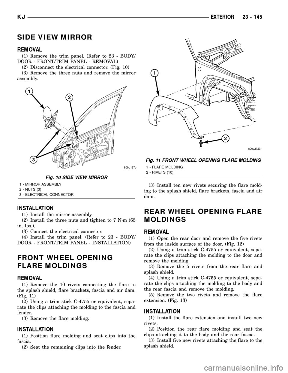
(2) Disconnect the electrical connector. (Fig. 10)
(3) Remove the three nuts and remove the mirror
assembly.
INSTALLATION
(1) Install the mirror assembly.
(2) Install the three nuts and tighten to 7 N´m (65
in. lbs.).
(3) Connect the electrical connector.
(4) Install the trim panel. (Refer to 23 - BODY/
DOOR - FRONT/TRIM PANEL - INSTALLATION)
FRONT WHEEL OPENING
FLARE MOLDINGS
REMOVAL
(1) Remove the 10 rivets connecting the flare to
the splash shield, flare brackets, fascia and air dam.
(Fig. 11)
(2) Using a trim stick C-4755 or equivalent, sepa-
rate the clips attaching the molding to the fascia and
fender.
(3) Remove the flare molding.
INSTALLATION
(1) Position flare molding and seat clips into the
fascia.
(2) Seat the remaining clips into the fender.(3) Install ten new rivets securing the flare mold-
ing to the splash shield, flare brackets, fascia and air
dam.
REAR WHEEL OPENING FLARE
MOLDINGS
REMOVAL
(1) Open the rear door and remove the five rivets
from the inside surface of the door. (Fig. 12)
(2) Using a trim stick C-4755 or equivalent, sepa-
rate the clips attaching the molding to the door and
remove the molding.
(3) Remove the 5 rivets from the rear flare and
splash shield.
(4) Using a trim stick C-4755 or equivalent, sepa-
rate the clips attaching the molding to the body and
the rear fascia and remove the molding.
(5) Remove the two rivets and remove the flare
extension. (Fig. 13)
INSTALLATION
(1) Install the flare extension and install two new
rivets.
(2) Position the rear flare molding and seat the
clips attaching it to the body and the rear fascia.
(3) Install five new rivets attaching the flare to the
splash shield.
Fig. 10 SIDE VIEW MIRROR
1 - MIRROR ASSEMBLY
2 - NUTS (3)
3 - ELECTRICAL CONNECTOR
Fig. 11 FRONT WHEEL OPENING FLARE MOLDING
1 - FLARE MOLDING
2 - RIVETS (10)
KJEXTERIOR 23 - 145
Page 1618 of 1803
INSTALLATION
WARNING: ON VEHICLES EQUIPPED WITH AIR-
BAGS, DISABLE THE AIRBAG SYSTEM BEFORE
ATTEMPTING ANY STEERING WHEEL, STEERING
COLUMN, SEAT BELT TENSIONER, OR INSTRU-
MENT PANEL COMPONENT DIAGNOSIS OR SER-
VICE. DISCONNECT AND ISOLATE THE BATTERY
NEGATIVE (GROUND) CABLE, THEN WAIT TWO
MINUTES FOR THE AIRBAG SYSTEM CAPACITOR
TO DISCHARGE BEFORE PERFORMING FURTHER
DIAGNOSIS OR SERVICE. THIS IS THE ONLY SURE
WAY TO DISABLE THE AIRBAG SYSTEM. FAILURE
TO TAKE THE PROPER PRECAUTIONS COULD
RESULT IN ACCIDENTAL AIRBAG DEPLOYMENT
AND POSSIBLE PERSONAL INJURY.
(1) Position the top cover and seat the clips fully.
(2) Install the a-pillar trim panels. (Refer to 23 -
BODY/INTERIOR/A-PILLAR TRIM AND GRAB
HANDLE - INSTALLATION)
INSTRUMENT PANEL END CAP
REMOVAL
WARNING: ON VEHICLES EQUIPPED WITH AIR-
BAGS, DISABLE THE AIRBAG SYSTEM BEFORE
ATTEMPTING ANY STEERING WHEEL, STEERING
COLUMN, SEAT BELT TENSIONER, OR INSTRU-
MENT PANEL COMPONENT DIAGNOSIS OR SER-
VICE. DISCONNECT AND ISOLATE THE BATTERY
NEGATIVE (GROUND) CABLE, THEN WAIT TWO
MINUTES FOR THE AIRBAG SYSTEM CAPACITOR
TO DISCHARGE BEFORE PERFORMING FURTHER
DIAGNOSIS OR SERVICE. THIS IS THE ONLY SURE
WAY TO DISABLE THE AIRBAG SYSTEM. FAILURE
TO TAKE THE PROPER PRECAUTIONS COULD
RESULT IN ACCIDENTAL AIRBAG DEPLOYMENT
AND POSSIBLE PERSONAL INJURY.
(1) Open the door.
(2) Using the finger indent, grasp and remove the
side cover. (Fig. 7)
INSTALLATION
WARNING: ON VEHICLES EQUIPPED WITH AIR-
BAGS, DISABLE THE AIRBAG SYSTEM BEFORE
ATTEMPTING ANY STEERING WHEEL, STEERING
COLUMN, SEAT BELT TENSIONER, OR INSTRU-
MENT PANEL COMPONENT DIAGNOSIS OR SER-
VICE. DISCONNECT AND ISOLATE THE BATTERY
NEGATIVE (GROUND) CABLE, THEN WAIT TWO
MINUTES FOR THE AIRBAG SYSTEM CAPACITOR
TO DISCHARGE BEFORE PERFORMING FURTHERDIAGNOSIS OR SERVICE. THIS IS THE ONLY SURE
WAY TO DISABLE THE AIRBAG SYSTEM. FAILURE
TO TAKE THE PROPER PRECAUTIONS COULD
RESULT IN ACCIDENTAL AIRBAG DEPLOYMENT
AND POSSIBLE PERSONAL INJURY.
(1) Position the side panels and seat the clips fully.
INSTRUMENT PANEL DRIVER
SIDE BEZELS
REMOVAL
WARNING: ON VEHICLES EQUIPPED WITH AIR-
BAGS, DISABLE THE AIRBAG SYSTEM BEFORE
ATTEMPTING ANY STEERING WHEEL, STEERING
COLUMN, SEAT BELT TENSIONER, OR INSTRU-
MENT PANEL COMPONENT DIAGNOSIS OR SER-
VICE. DISCONNECT AND ISOLATE THE BATTERY
NEGATIVE (GROUND) CABLE, THEN WAIT TWO
MINUTES FOR THE AIRBAG SYSTEM CAPACITOR
TO DISCHARGE BEFORE PERFORMING FURTHER
DIAGNOSIS OR SERVICE. THIS IS THE ONLY SURE
WAY TO DISABLE THE AIRBAG SYSTEM. FAILURE
TO TAKE THE PROPER PRECAUTIONS COULD
RESULT IN ACCIDENTAL AIRBAG DEPLOYMENT
AND POSSIBLE PERSONAL INJURY.
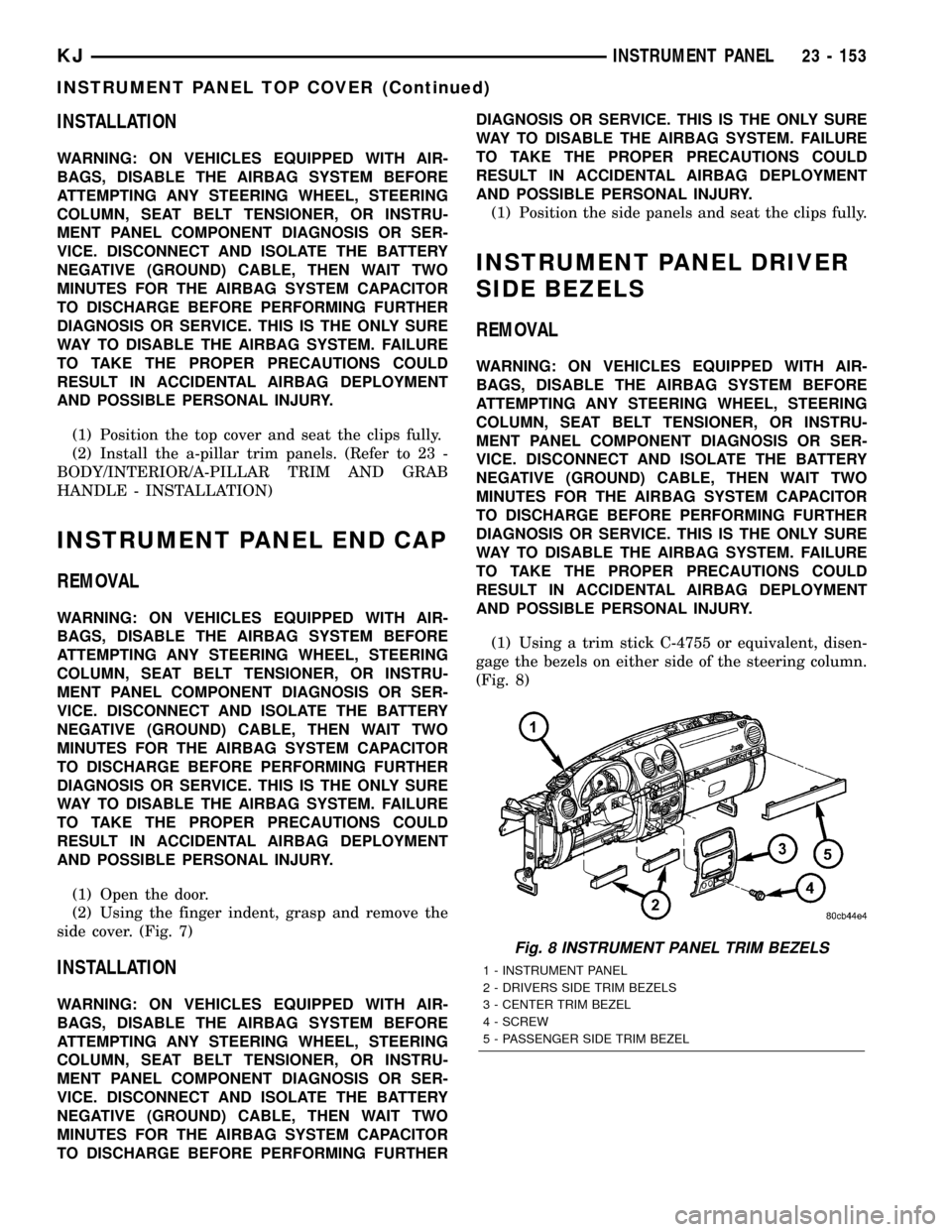
(1) Using a trim stick C-4755 or equivalent, disen-
gage the bezels on either side of the steering column.
(Fig. 8)
Fig. 8 INSTRUMENT PANEL TRIM BEZELS
1 - INSTRUMENT PANEL
2 - DRIVERS SIDE TRIM BEZELS
3 - CENTER TRIM BEZEL
4 - SCREW
5 - PASSENGER SIDE TRIM BEZEL
KJINSTRUMENT PANEL 23 - 153
INSTRUMENT PANEL TOP COVER (Continued)
Page 1621 of 1803
INTERIOR
TABLE OF CONTENTS
page page
4WD FLOOR SHIFT BOOT
REMOVAL............................156
INSTALLATION........................156
A-PILLAR TRIM AND GRAB HANDLE
REMOVAL............................156
INSTALLATION........................156
COWL TRIM COVER
REMOVAL............................157
INSTALLATION........................157
DOOR SILL SCUFF PLATE
REMOVAL............................157
INSTALLATION........................157
ASSIST HANDLE
REMOVAL............................157
INSTALLATION........................157
B-PILLAR LOWER TRIM
REMOVAL............................157
INSTALLATION........................157
B-PILLAR UPPER TRIM
REMOVAL............................157
INSTALLATION........................158
CARPETS AND FLOOR MATS
REMOVAL............................158
INSTALLATION........................158
SHIFT BEZEL
REMOVAL............................158
INSTALLATION........................158FLOOR CONSOLE
REMOVAL............................158
INSTALLATION........................158
FLOOR CONSOLE LID LATCH
REMOVAL............................158
INSTALLATION........................158
HEADLINER
REMOVAL............................159
INSTALLATION........................159
QUARTER TRIM PANEL
REMOVAL............................159
INSTALLATION........................159
REAR DOOR SCUFF PLATE
REMOVAL............................160
INSTALLATION........................160
SUN VISOR
REMOVAL............................160
INSTALLATION........................160
SUN VISOR SUPPORT
REMOVAL............................160
INSTALLATION........................160
REAR VIEW MIRROR
REMOVAL............................161
INSTALLATION
INSTALLATION......................161
INSTALLATION - REARVIEW MIRROR
SUPPORT BRACKET..................161
4WD FLOOR SHIFT BOOT
REMOVAL
(1) Remove the shift lever and remove the boot
from the lever. (Refer to 21 - TRANSMISSION/
TRANSAXLE/TRANSFER CASE/SHIFT LEVER -
REMOVAL)
INSTALLATION
(1) Install the shift boot onto the shift lever and
install the lever. (Refer to 21 - TRANSMISSION/
TRANSAXLE/TRANSFER CASE/SHIFT LEVER -
INSTALLATION)
A-PILLAR TRIM AND GRAB
HANDLE
REMOVAL
(1) Using a small pry tool or equivalent, remove
the grab handle trim plugs.
(2) Remove the two grab handle screws.
(3) Remove the grab handle and a-pillar trim from
the a-pillar.
INSTALLATION
(1) Snap a-pillar trim and grab handle into the
a-pillar.
(2) Install the two screws and install the grab han-
dle trim plugs.
23 - 156 INTERIORKJ
Page 1622 of 1803
COWL TRIM COVER
REMOVAL
(1) Remove the lower b-pillar trim. (Refer to 23 -
BODY/INTERIOR/B-PILLAR LOWER TRIM -
REMOVAL)
(2) Remove the cowl trim cover by pulling it away
from the a-pillar and releasing the clips.
INSTALLATION
(1) Install the cowl trim cover and seat the retain-
ing clips.
(2) Install the lower b-pillar trim. (Refer to 23 -
BODY/INTERIOR/B-PILLAR LOWER TRIM -
INSTALLATION)
DOOR SILL SCUFF PLATE
REMOVAL
(1) Using a trim stick C-4755 or equivalent, pry up
the scuff plate releasing the retaining clips.
INSTALLATION
(1) Position the scuff plate and seat the retaining
clips.
ASSIST HANDLE
REMOVAL
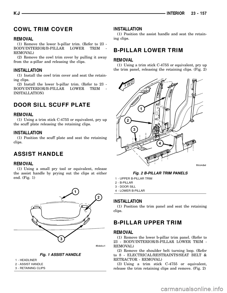
(1) Using a small pry tool or equivalent, release
the assist handle by prying out the clips at either
end. (Fig. 1)
INSTALLATION
(1) Position the assist handle and seat the retain-
ing clips.
B-PILLAR LOWER TRIM
REMOVAL
(1) Using a trim stick C-4755 or equivalent, pry up
the trim panel, releasing the retaining clips. (Fig. 2)
INSTALLATION
(1) Position the trim panel and seat the retaining
clips.
B-PILLAR UPPER TRIM
REMOVAL
(1) Remove the lower b-pillar trim panel. (Refer to
23 - BODY/INTERIOR/B-PILLAR LOWER TRIM -
REMOVAL)
(2) Remove the shoulder belt turning loop. (Refer
to 8 - ELECTRICAL/RESTRAINTS/SEAT BELT &
RETRACTOR - REMOVAL)
(3) Using a trim stick C-4755 or equivalent,
release the trim retaining clips and remove. (Fig. 2)
Fig. 1 ASSIST HANDLE
1 - HEADLINER
2 - ASSIST HANDLE
3 - RETAINING CLIPS
Fig. 2 B-PILLAR TRIM PANELS
1 - UPPER B-PILLAR TRIM
2 - B-PILLAR
3 - DOOR SILL
4 - LOWER B-PILLAR
KJINTERIOR 23 - 157
Page 1625 of 1803
(3) Install the belt access panel.
(4) Install the seat belt anchor and pivot. (Refer to
8 - ELECTRICAL/RESTRAINTS/SEAT BELT &
RETRACTOR - INSTALLATION)
(5) Install the hook pin type connector.
(6) Position the rear sill plate and seat the retain-
ing clips.
(7) Position the rear header trim and seat the
retaining clips.
REAR DOOR SCUFF PLATE
REMOVAL
(1) Using a trim stick C-4755 or equivalent,
release the retaining clips and remove the scuff
plate.
INSTALLATION
(1) Position the scuff plate and seat the retaining
clips.
SUN VISOR
REMOVAL
(1) Remove the screws at the visor pivot.
(2) Disconnect the electrical connector and remove
the visor.
INSTALLATION
(1) Connect the electrical connector and install the
visor.
(2) Install the screws at the visor pivots.
SUN VISOR SUPPORT
REMOVAL
(1) Using a small pry tool or equivalent, release
the support retaining clip by prying out and remove
the support. (Fig. 5)
INSTALLATION
(1) Position the visor support and seat the retain-
ing clip.
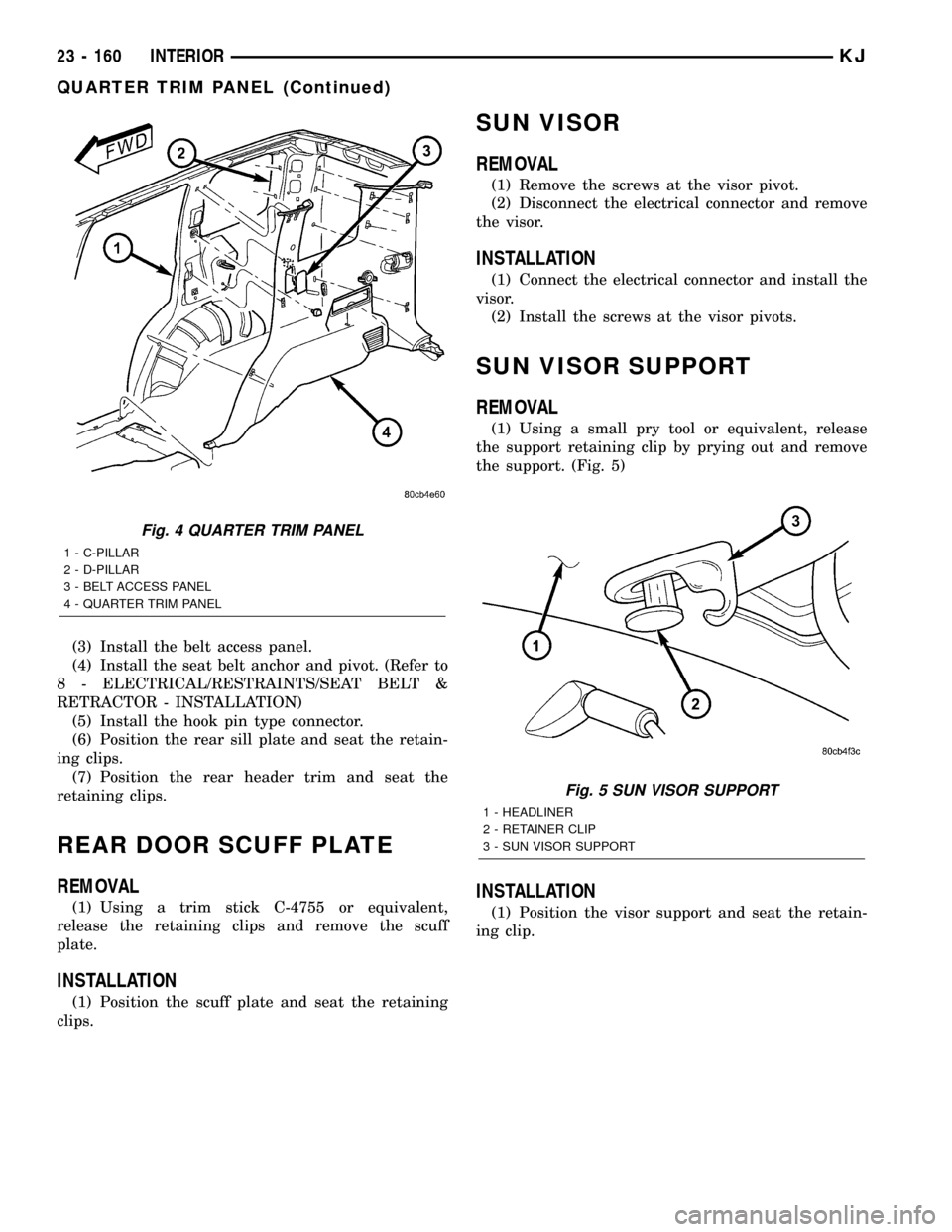
Fig. 4 QUARTER TRIM PANEL
1 - C-PILLAR
2 - D-PILLAR
3 - BELT ACCESS PANEL
4 - QUARTER TRIM PANEL
Fig. 5 SUN VISOR SUPPORT
1 - HEADLINER
2 - RETAINER CLIP
3 - SUN VISOR SUPPORT
23 - 160 INTERIORKJ
QUARTER TRIM PANEL (Continued)
Page 1650 of 1803

WEATHERSTRIP/SEALS
TABLE OF CONTENTS
page page
A-PILLAR SEAL
REMOVAL............................185
INSTALLATION........................185
COWL WEATHERSTRIP
REMOVAL............................185
INSTALLATION........................185
DOOR PRIMARY WEATHERSTRIP
REMOVAL............................185
INSTALLATION........................185
DOOR LOWER WEATHERSTRIP
REMOVAL............................186
INSTALLATION........................186
FRONT DOOR OUTER BELT MOLDING
REMOVAL............................186
INSTALLATION........................186
SWING GATE BELTLINE WEATHERSTRIP
REMOVAL............................186
INSTALLATION........................186
SWING GATE OPENING WEATHERSTRIP
REMOVAL............................186INSTALLATION........................186
REAR DOOR OUTER BELT MOLDING
REMOVAL............................186
INSTALLATION........................186
SIDE RAIL WEATHERSTRIP/RETAINER
REMOVAL............................186
INSTALLATION........................186
WINDSHIELD A-PILLAR WEATHERSTRIP/
RETAINER
REMOVAL............................186
INSTALLATION........................187
COWL/PLENUM SEAL
REMOVAL............................187
INSTALLATION........................187
COWL/PLENUM WINDOW BAFFLE SEAL
REMOVAL............................187
INSTALLATION........................187
A-PILLAR SEAL
REMOVAL
(1) Open the doors and peal the seal away from
the a-pillar/windshield and the side rail weather
strip flanges.
INSTALLATION
(1) Position the a-pillar seal over the windshield/a-
pillar and the side rail weatherstrip flanges and seat
fully.
COWL WEATHERSTRIP
REMOVAL
(1) Open the hood and peal the cowl seal from the
cowl panel and cowl flange.
INSTALLATION
(1) Position the weatherstrip over the cowl flange
and the cowl grille and seat fully.
DOOR PRIMARY
WEATHERSTRIP
REMOVAL
(1) Remove the lower b-pillar trim. (Refer to 23 -
BODY/INTERIOR/B-PILLAR LOWER TRIM -
REMOVAL)
(2) Peal seal off of the door opening flange.
INSTALLATION
(1) Position the seal to the bottom of the door
opening, with bulb facing outboard, starting the
installation at the center of the lower flange. Press
the seal onto the sill flange and work around the
perimeter of the door opening until fully seated.
Work in one direction, smoothing the seal to avoid
puckers or wrinkles.
(2) Install the lower b-pillar trim. (Refer to 23 -
BODY/INTERIOR/B-PILLAR LOWER TRIM -
INSTALLATION)
(3) When installing a new weatherstrip on the
front door opening, remove the tear strip starting at
the splice and moving around the front of the door to
the back of the opening.
KJWEATHERSTRIP/SEALS 23 - 185
Page 1651 of 1803
(4) When installing a new weatherstrip on the rear
door opening, remove the tear strip starting at the
splice and moving around the back of the door to the
front of the opening.
DOOR LOWER WEATHERSTRIP
REMOVAL
(1) Carefully disengage the push pin fasteners and
remove the seal.
INSTALLATION
(1) Position the seal and seat the push pin fasten-
ers.
FRONT DOOR OUTER BELT
MOLDING
REMOVAL
(1) Lower the window.
(2) Pull the outer belt molding off of the door
flange starting at the rear and moving forward.
INSTALLATION
(1) Press the belt molding onto the outer door win-
dow flange starting at the rear and working forward.
SWING GATE BELTLINE
WEATHERSTRIP
REMOVAL
(1) Remove the swing gate trim panel. (Refer to 23
- BODY/SWING GATE/TRIM PANEL - REMOVAL)
(2) Pull seal away from the corner tabs and
remove from the swing gate flange.
INSTALLATION
(1) Install the seal over the swing gate flange and
seat the corner tabs.
(2) Install the swing gate trim panel. (Refer to 23 -
BODY/SWING GATE/TRIM PANEL - INSTALLA-
TION)
SWING GATE OPENING
WEATHERSTRIP
REMOVAL
(1) Open the swing gate and peal seal off of the
gate opening flange.
INSTALLATION
(1) Position the seal to the bottom of the gate
opening starting the installation at the center of the
flange. Press the seal onto the sill flange and work
around the perimeter of the door opening until fully
seated. Work in one direction, smoothing the seal to
avoid puckers or wrinkles.
REAR DOOR OUTER BELT
MOLDING
REMOVAL
(1) Lower the window.
(2) Pull the outer belt molding off of the door
flange starting at the rear and moving forward.
INSTALLATION
(1) Press the belt molding onto the outer door win-
dow flange starting at the front and working back.
SIDE RAIL WEATHERSTRIP/
RETAINER
REMOVAL
(1) Remove the windshield weatherstrip retainer.
(Refer to 23 - BODY/WEATHERSTRIP/SEALS/
WINDSHIELD A-PILLAR WEATHERSTRIP/RE-
TAINER - REMOVAL)
(2) Remove the two screws.
(3) Using a trim stick C-4755 or equivalent,
release the push in fasteners and remove the weath-
erstrip.
INSTALLATION
(1) Position the weatherstrip and seat the push in
fasteners.
(2) Install the two screws.
(3) Install the windshield weatherstrip. (Refer to
23 - BODY/WEATHERSTRIP/SEALS/WINDSHIELD
A-PILLAR WEATHERSTRIP/RETAINER - INSTAL-
LATION)
WINDSHIELD A-PILLAR
WEATHERSTRIP/RETAINER
REMOVAL
(1) Open the doors and peal the a-pillar seal away
from the a-pillar/windshield and the side rail
weather strip flanges.
(2) Remove the seven screws and remove the
weatherstrip.
23 - 186 WEATHERSTRIP/SEALSKJ
DOOR PRIMARY WEATHERSTRIP (Continued)