2002 JEEP LIBERTY fuel cap release
[x] Cancel search: fuel cap releasePage 762 of 1803

8W-02 COMPONENT INDEX
Component Page
A/C Compressor Clutch Relay........... 8Wa-42
A/C Compressor Clutch................ 8Wa-42
A/C-Heater Control................... 8Wa-42
A/C High Pressure Switch.............. 8Wa-42
A/C Low Pressure Switch............... 8Wa-42
A/C Pressure Transducer............... 8Wa-42
Accelerator Pedal Position Sensor........ 8Wa-30
Airbag Control Module................. 8Wa-43
Ambient Temperature Sensor............ 8Wa-45
Antenna Module...................... 8Wa-47
Antenna............................ 8Wa-47
Ash Receiver Lamp................... 8Wa-44
Auto Shut Down Relay................. 8Wa-30
Back-Up Lamp Switch................. 8Wa-31
Battery Temperature Sensor......... 8Wa-20, 30
Battery............................. 8Wa-20
Blend Door Actuator................... 8Wa-42
Blower Motor Relay................... 8Wa-42
Blower Motor Resistor Block............ 8Wa-42
Blower Motor........................ 8Wa-42
Body Control Module.................. 8Wa-45
Boost Pressure Sensor................. 8Wa-30
Brake Lamp Switch................... 8Wa-33
Brake Pressure Switch................. 8Wa-35
Cabin Heater Relay................... 8Wa-42
Cabin Heater........................ 8Wa-42
Camshaft Position Sensor.............. 8Wa-30
Capacitor........................... 8Wa-30
Cargo Lamp......................... 8Wa-44
CD Changer......................... 8Wa-47
Center High Mounted Stop Lamp........ 8Wa-51
Cigar Lighter........................ 8Wa-41
Circuit Breakers...................... 8Wa-12
Clockspring................. 8Wa-33, 41, 43, 47
Clutch Interlock Switch................ 8Wa-21
Clutch Switch Override Relay........... 8Wa-21
Coil On Plugs........................ 8Wa-30
Coil Rail............................ 8Wa-30
Compass Mini-Trip Computer........... 8Wa-49
Controller Antilock Brake.............. 8Wa-35
Courtesy Lamps...................... 8Wa-44
Crankshaft Position Sensor............. 8Wa-30
Curtain Airbags...................... 8Wa-43
Cylinder Lock Switches................ 8Wa-61
Data Link Connector.................. 8Wa-18
Daytime Running Lamp Relay........... 8Wa-50
Defogger Relay....................... 8Wa-48
Diagnostic Junction Port............... 8Wa-18
Dome Lamp......................... 8Wa-44
Door Ajar Switches.................... 8Wa-45
Door Lock Motor/Ajar Switches.......... 8Wa-61
Door Lock Relay...................... 8Wa-61Component Page
Door Lock Switches................... 8Wa-61
Door Speakers....................... 8Wa-47
Driver Airbag Squib 1................. 8Wa-43
Driver Airbag Squib 2................. 8Wa-43
Driver Door Unlock Relay.............. 8Wa-61
Driver Seat Belt Switch................ 8Wa-40
Driver Seat Belt Tensioner.............. 8Wa-43
EGR Solenoid........................ 8Wa-30
Electric Brake Provision................ 8Wa-54
Engine Control Module................ 8Wa-30
Engine Coolant Level Sensor............ 8Wa-40
Engine Coolant Temperature Sensor...... 8Wa-30
Engine Oil Pressure Sensor............. 8Wa-30
EVAP/Purge Solenoid.................. 8Wa-30
Flip-Up Glass Release Motor............ 8Wa-61
Flip-Up Glass Release Switch........... 8Wa-61
Fog Lamps.......................... 8Wa-50
Front Fog Lamp Relay................. 8Wa-50
Front Wiper Motor.................... 8Wa-53
Fuel Heater Relay.................... 8Wa-30
Fuel Heater......................... 8Wa-30
Fuel Injectors........................ 8Wa-30
Fuel Pressure Sensor.................. 8Wa-30
Fuel Pressure Solenoid................. 8Wa-30
Fuel Pump Module.................... 8Wa-30
Fuel Pump Relay..................... 8Wa-30
Fuses........................... 8Wa-10, 12
Fusible Link......................... 8Wa-20
Grounds............................ 8Wa-15
Generator........................... 8Wa-20
Glow Plugs.......................... 8Wa-30
Hazard Switch/Combination Flasher...... 8Wa-52
Headlamp Leveling Switch.............. 8Wa-50
Headlamps.......................... 8Wa-50
Heated Seats........................ 8Wa-63
High Beam Relay..................... 8Wa-50
Horns.............................. 8Wa-41
Hood Ajar Switch..................... 8Wa-45
Idle Air Control Motor................. 8Wa-30
Ignition Switch....................... 8Wa-10
Impact Sensors....................... 8Wa-43
Input Speed Sensor................... 8Wa-31
Instrument Cluster................... 8Wa-40
Instrument Panel Speakers............. 8Wa-47
Intake Air Temperature Sensor.......... 8Wa-30
Intrusion Sensor..................... 8Wa-49
Junction Block....................... 8Wa-12
Knock Sensor........................ 8Wa-30
Leak Detection Pump.................. 8Wa-30
Leveling Motors...................... 8Wa-50
License Lamp........................ 8Wa-51
Line Pressure Sensor.................. 8Wa-31
KJ8W-02 COMPONENT INDEX8Wa-02-1
Page 830 of 1803

8W-15 GROUND DISTRIBUTION
Component Page
A/C Compressor Clutch...................8Wa-15-6
A/C Low Pressure Switch.................8Wa-15-3
A/C- Heater Control...................8Wa-15-7, 8
Airbag Control Module...................8Wa-15-7
Ash Receiver Lamp.....................8Wa-15-8
Battery.............................8Wa-15-2
Blend Door Actuator.....................8Wa-15-8
Blower Motor Relay.....................8Wa-15-4
Body Control Module....................8Wa-15-8
Brake Lamp Switch.....................8Wa-15-8
Cabin Heater.........................8Wa-15-6
Capacitor............................8Wa-15-2
Center High Mounted Stop Lamp...........8Wa-15-14
Cigar Lighter.........................8Wa-15-8
Compass Mini-Trip Computer..............8Wa-15-14
Controller Antilock Brake.................8Wa-15-2
Data Link Connector....................8Wa-15-2
Engine Control Module...................8Wa-15-7
Engine Coolant Level Sensor...............8Wa-15-6
Flip-Up Glass Release Motor..............8Wa-15-14
Front Wiper Motor......................8Wa-15-3
Fuel Heater..........................8Wa-15-6
Fuel Heater Relay......................8Wa-15-4
Fuel Pump Module.....................8Wa-15-15
G100.............................8Wa-15-2, 7
G101...............................8Wa-15-6
G102...............................8Wa-15-2
G103...............................8Wa-15-6
G104...............................8Wa-15-7
G105...............................8Wa-15-2
G106...............................8Wa-15-2
G110...............................8Wa-15-2
G111 .............................8Wa-15-3, 4
G112...............................8Wa-15-3
G200...............................8Wa-15-7
G201...............................8Wa-15-7
G202...............................8Wa-15-8
G300............................8Wa-15-9, 11
G301............................8Wa-15-9, 10
G302............................8Wa-15-9, 12
G310.........................8Wa-15-13, 14, 15
G311 ..............................8Wa-15-14
G312..............................8Wa-15-14
G320..............................8Wa-15-15
Hazard Switch/Combination Flasher..........8Wa-15-8
Headlamp Leveling Switch................8Wa-15-8
Heated Seat Module....................8Wa-15-10
High Note Horn.......................8Wa-15-3
Hood Ajar Switch.......................8Wa-15-4
Ignition Switch........................8Wa-15-8
Instrument Cluster.....................8Wa-15-8
Intrusion Sensor......................8Wa-15-14
Junction Block........................8Wa-15-8
Left Door Lock Switch...................8Wa-15-11
Left Fog Lamp........................8Wa-15-5
Left Front Door Ajar Switch...............8Wa-15-11
Left Front Door Lock Motor/Ajar Switch.......8Wa-15-11
Left Front Door Speaker..................8Wa-15-7
Left Front Park/Turn Signal Lamp...........8Wa-15-5
Left Headlamp........................8Wa-15-3
Left Heated Seat Assembly...............8Wa-15-10
Left Heated Seat Switch.................8Wa-15-10Component Page
Left Leveling Motor.....................8Wa-15-3
Left Position Lamp.....................8Wa-15-3
Left Power Mirror.....................8Wa-15-11
Left Power Seat Switch..................8Wa-15-10
Left Rear Door Ajar Switch...............8Wa-15-11
Left Rear Door Lock Motor/Ajar Switch.......8Wa-15-11
Left Side Impact Airbag Control Module........8Wa-15-9
Left Side Repeater Lamp..................8Wa-15-5
Left Tail/Stop Lamp....................8Wa-15-15
License Lamp........................8Wa-15-15
Line Pressure Sensor....................8Wa-15-2
Low Note Horn........................8Wa-15-3
Multi- Function Switch...................8Wa-15-8
Oxygen Sensor 1/2 Downstream.............8Wa-15-6
Oxygen Sensor 2/2 Downstream.............8Wa-15-6
Power Mirror Switch.................8Wa-15-11, 12
Power Outlet.........................8Wa-15-8
Power Steering Pressure Switch.............8Wa-15-6
Power Window Master Switch.............8Wa-15-10
Powertrain Control Module................8Wa-15-2
Radiator Fan Motor.....................8Wa-15-3
Radiator Fan Relay.....................8Wa-15-3
Radio..............................8Wa-15-7
Radio Choke..........................8Wa-15-9
Rear Power Outlet.....................8Wa-15-15
Rear Window Defogger..................8Wa-15-14
Rear Wiper Motor.....................8Wa-15-14
Red Brake Warning Indicator Switch..........8Wa-15-4
Right Door Lock Switch..................8Wa-15-12
Right Fog Lamp.......................8Wa-15-5
Right Front Door Ajar Switch..............8Wa-15-12
Right Front Door Lock Motor/Ajar Switch......8Wa-15-12
Right Front Door Speaker.................8Wa-15-7
Right Front Park/Turn Signal Lamp..........8Wa-15-5
Right Headlamp.......................8Wa-15-4
Right Heated Seat Assembly..............8Wa-15-10
Right Heated Seat Switch................8Wa-15-10
Right Leveling Motor....................8Wa-15-4
Right Position Lamp....................8Wa-15-4
Right Power Mirror....................8Wa-15-12
Right Power Seat Switch.................8Wa-15-10
Right Rear Door Ajar Switch..............8Wa-15-12
Right Rear Door Lock Motor/Ajar Switch......8Wa-15-12
Right Side Impact Airbag Control Module.......8Wa-15-9
Right Side Repeater Lamp.................8Wa-15-5
Right Tail/Stop Lamp...................8Wa-15-15
Sentry Key Immobilizer Module.............8Wa-15-8
Shifter Assembly.......................8Wa-15-9
Siren...............................8Wa-15-4
Speed Control Servo.....................8Wa-15-3
Starter Motor Relay.....................8Wa-15-4
Sunroof Motor........................8Wa-15-14
Tailgate Flip-Up Ajar Switch..............8Wa-15-14
Trailer Tow Brake Lamp Relay.............8Wa-15-13
Trailer Tow Connector...................8Wa-15-13
Trailer Tow Left Turn Relay...............8Wa-15-13
Trailer Tow Relay......................8Wa-15-13
Trailer Tow Right Turn Relay..............8Wa-15-13
Transmission Control Module...............8Wa-15-2
Transmission Control Relay................8Wa-15-4
Washer Fluid Level Switch................8Wa-15-3
KJ8W-15 GROUND DISTRIBUTION8Wa-15-1
Page 1057 of 1803
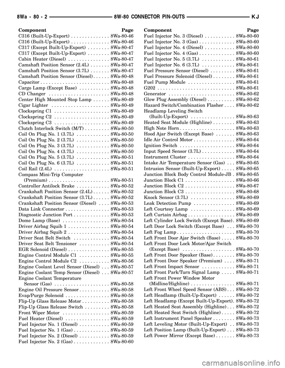
Component Page
C316 (Built-Up-Export).............. 8Wa-80-46
C316 (Built-Up-Export).............. 8Wa-80-46
C317 (Except Built-Up-Export)........ 8Wa-80-47
C317 (Except Built-Up-Export)........ 8Wa-80-47
Cabin Heater (Diesel)............... 8Wa-80-47
Camshaft Position Sensor (2.4L)....... 8Wa-80-47
Camshaft Position Sensor (3.7L)....... 8Wa-80-47
Camshaft Position Sensor (Diesel)...... 8Wa-80-48
Capacitor......................... 8Wa-80-48
Cargo Lamp (Except Base)........... 8Wa-80-48
CD Changer...................... 8Wa-80-48
Center High Mounted Stop Lamp...... 8Wa-80-49
Cigar Lighter..................... 8Wa-80-49
Clockspring C1.................... 8Wa-80-49
Clockspring C2.................... 8Wa-80-49
Clockspring C3.................... 8Wa-80-49
Clutch Interlock Switch (M/T)......... 8Wa-80-50
Coil On Plug No. 1 (3.7L)............ 8Wa-80-50
Coil On Plug No. 2 (3.7L)............ 8Wa-80-50
Coil On Plug No. 3 (3.7L)............ 8Wa-80-50
Coil On Plug No. 4 (3.7L)............ 8Wa-80-50
Coil On Plug No. 5 (3.7L)............ 8Wa-80-51
Coil On Plug No. 6 (3.7L)............ 8Wa-80-51
Coil Rail (2.4L).................... 8Wa-80-51
Compass Mini-Trip Computer
(Premium)...................... 8Wa-80-51
Controller Antilock Brake............ 8Wa-80-52
Crankshaft Position Sensor (2.4L)...... 8Wa-80-52
Crankshaft Position Sensor (3.7L)...... 8Wa-80-52
Crankshaft Position Sensor (Diesel).... 8Wa-80-53
Data Link Connector................ 8Wa-80-53
Diagnostic Junction Port............. 8Wa-80-53
Dome Lamp (Base)................. 8Wa-80-54
Driver Airbag Squib 1............... 8Wa-80-54
Driver Airbag Squib 2............... 8Wa-80-54
Driver Seat Belt Switch............. 8Wa-80-54
Driver Seat Belt Tensioner........... 8Wa-80-54
EGR Solenoid (Diesel)............... 8Wa-80-55
Engine Control Module C1........... 8Wa-80-55
Engine Control Module C2........... 8Wa-80-56
Engine Coolant Level Sensor (Diesel) . . . 8Wa-80-57
Engine Coolant Temp Sensor (Diesel) . . . 8Wa-80-57
Engine Coolant Temperature
Sensor (Gas).................... 8Wa-80-58
Engine Oil Pressure Sensor........... 8Wa-80-58
Evap/Purge Solenoid................ 8Wa-80-58
Flip-Up Glass Release Motor.......... 8Wa-80-58
Flip-Up Glass Release Switch......... 8Wa-80-58
Front Wiper Motor................. 8Wa-80-59
Fuel Heater (Diesel)................ 8Wa-80-59
Fuel Injector No. 1 (Diesel)........... 8Wa-80-59
Fuel Injector No. 1 (Gas)............. 8Wa-80-59
Fuel Injector No. 2 (Diesel)........... 8Wa-80-59
Fuel Injector No. 2 (Gas)............. 8Wa-80-60Component Page
Fuel Injector No. 3 (Diesel)........... 8Wa-80-60
Fuel Injector No. 3 (Gas)............. 8Wa-80-60
Fuel Injector No. 4 (Diesel)........... 8Wa-80-60
Fuel Injector No. 4 (Gas)............. 8Wa-80-60
Fuel Injector No. 5 (3.7L)............ 8Wa-80-61
Fuel Injector No. 6 (3.7L)............ 8Wa-80-61
Fuel Pressure Sensor (Diesel)......... 8Wa-80-61
Fuel Pressure Solenoid (Diesel)........ 8Wa-80-61
Fuel Pump Module................. 8Wa-80-61
G202............................ 8Wa-80-61
Generator........................ 8Wa-80-62
Glow Plug Assembly (Diesel).......... 8Wa-80-62
Hazard Switch/Combination Flasher.... 8Wa-80-62
Headlamp Leveling Switch
(Built-Up-Export)................ 8Wa-80-63
Heated Seat Module (Highline)........ 8Wa-80-63
High Note Horn.................... 8Wa-80-63
Hood Ajar Switch (Except Base)....... 8Wa-80-63
Idle Air Control Motor............... 8Wa-80-64
Ignition Switch.................... 8Wa-80-64
Input Speed Sensor (3.7L)............ 8Wa-80-64
Instrument Cluster................. 8Wa-80-64
Intake Air Temperature Sensor (Gas) . . . 8Wa-80-65
Intrusion Sensor (Built-Up-Export)..... 8Wa-80-65
Junction Block Body Control Module-JB . 8Wa-80-65
Junction Block C1.................. 8Wa-80-66
Junction Block C2.................. 8Wa-80-67
Junction Block C3.................. 8Wa-80-68
Knock Sensor (3.7L)................ 8Wa-80-69
Leak Detection Pump............... 8Wa-80-69
Left Courtesy Lamp................ 8Wa-80-69
Left Curtain Airbag................. 8Wa-80-69
Left Cylinder Lock Switch (Except Base) . 8Wa-80-69
Left Door Lock Switch (Except Base) . . . 8Wa-80-70
Left Fog Lamp..................... 8Wa-80-70
Left Front Door Ajar Switch (Base)..... 8Wa-80-70
Left Front Door Lock Motor/Ajar Switch
(Except Base)................... 8Wa-80-70
Left Front Door Speaker (Base)........ 8Wa-80-70
Left Front Door Speaker (Premium).... 8Wa-80-71
Left Front Impact Sensor............ 8Wa-80-71
Left Front Park/Turn Signal Lamp..... 8Wa-80-71
Left Front Power Window Motor
(Midline/Highline)................ 8Wa-80-71
Left Front Wheel Speed Sensor (ABS) . . . 8Wa-80-72
Left Headlamp (Built-Up-Export)...... 8Wa-80-72
Left Headlamp (Except Built-Up-Export) . 8Wa-80-72
Left Heated Seat Assembly (Highline) . . . 8Wa-80-72
Left Heated Seat Switch (Highline)..... 8Wa-80-72
Left Instrument Panel Speaker........ 8Wa-80-73
Left Leveling Motor (Built-Up-Export) . . 8Wa-80-73
Left Position Lamp (Built-Up-Export) . . . 8Wa-80-73
Left Power Mirror (Except Base)....... 8Wa-80-73
8Wa - 80 - 2 8W-80 CONNECTOR PIN-OUTSKJ
Page 1235 of 1803
Possible indications of the cylinder head gasket
leaking between adjacent cylinders are:
²Loss of engine power
²Engine misfiring
²Poor fuel economy
Possible indications of the cylinder head gasket
leaking between a cylinder and an adjacent water
jacket are:
²Engine overheating
²Loss of coolant
²Excessive steam (white smoke) emitting from
exhaust
²Coolant foaming
CYLINDER-TO-CYLINDER LEAKAGE TEST
To determine if an engine cylinder head gasket is
leaking between adjacent cylinders, follow the proce-
dures in Cylinder Compression Pressure Test (Refer
to 9 - ENGINE - DIAGNOSIS AND TESTING). An
engine cylinder head gasket leaking between adja-
cent cylinders will result in approximately a 50±70%
reduction in compression pressure.
CYLINDER-TO-WATER JACKET LEAKAGE TEST
WARNING: USE EXTREME CAUTION WHEN THE
ENGINE IS OPERATING WITH COOLANT PRES-
SURE CAP REMOVED.
VISUAL TEST METHOD
With the engine cool, remove the coolant pressure
cap. Start the engine and allow it to warm up until
thermostat opens.
If a large combustion/compression pressure leak
exists, bubbles will be visible in the coolant.
COOLING SYSTEM TESTER METHOD
WARNING: WITH COOLING SYSTEM TESTER IN
PLACE, PRESSURE WILL BUILD UP FAST. EXCES-
SIVE PRESSURE BUILT UP, BY CONTINUOUS
ENGINE OPERATION, MUST BE RELEASED TO A
SAFE PRESSURE POINT. NEVER PERMIT PRES-
SURE TO EXCEED 138 kPa (20 psi).
Install Cooling System Tester 7700 or equivalent to
pressure cap neck. Start the engine and observe the
tester's pressure gauge. If gauge pulsates with every
power stroke of a cylinder a combustion pressure
leak is evident.
CHEMICAL TEST METHOD
Combustion leaks into the cooling system can also
be checked by using Bloc-Chek Kit C-3685-A or
equivalent. Perform test following the procedures
supplied with the tool kit.
REMOVAL
(1) Disconnect the negative cable from the battery.
(2) Raise the vehicle on a hoist.
(3) Disconnect the exhaust pipe at the left side
exhaust manifold.
(4) Drain the engine coolant. Refer to COOLING
SYSTEM.
(5) Lower the vehicle.
(6) Remove the intake manifold. Refer to proce-
dure in this section.
(7) Remove the cylinder head cover. Refer to proce-
dure in this section.
(8) Remove the fan shroud and fan blade assembly.
Refer to COOLING SYSTEM.
(9) Remove accessory drive belt. Refer to COOL-
ING SYSTEM.
(10) Remove the power steering pump and set
aside.
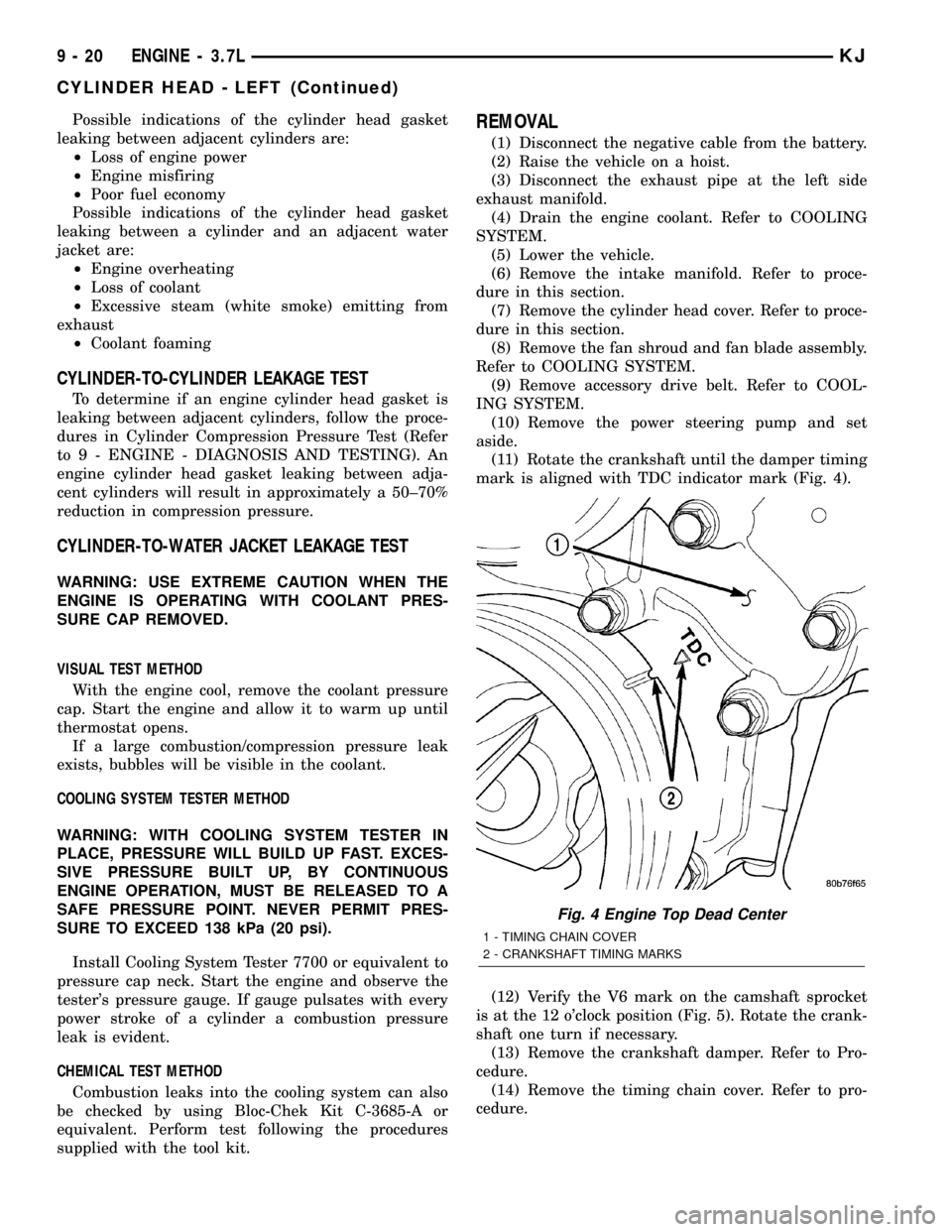
(11) Rotate the crankshaft until the damper timing
mark is aligned with TDC indicator mark (Fig. 4).
(12) Verify the V6 mark on the camshaft sprocket
is at the 12 o'clock position (Fig. 5). Rotate the crank-
shaft one turn if necessary.
(13) Remove the crankshaft damper. Refer to Pro-
cedure.
(14) Remove the timing chain cover. Refer to pro-
cedure.
Fig. 4 Engine Top Dead Center
1 - TIMING CHAIN COVER
2 - CRANKSHAFT TIMING MARKS
9 - 20 ENGINE - 3.7LKJ
CYLINDER HEAD - LEFT (Continued)
Page 1316 of 1803
AIR CLEANER ELEMENT
REMOVAL - 2.4L
Housing removal is not necessary for element (fil-
ter) replacement.
(1) Disconnect air intake duct at side of element
cover.
(2) Pry up 2 spring clips from front of housing
cover (spring clips retain cover to housing).
(3) Release housing cover from locating tabs
located on rear of housing, and remove cover.
(4) Remove air cleaner element (filter) from hous-
ing.
(5) Clean inside of housing before replacing ele-
ment.
INSTALLATION - 2.4L
(1) Install element into housing.
(2) Position housing cover into housing locating
tabs.
(3) Pry up spring clips and lock cover to housing.
(4) Connect air intake duct.
If any air filter, air resonator, air intake tubes or
air filter housing clamps had been loosened or
removed, tighten them to 5 N´m (40 in. lbs.) torque.
CYLINDER HEAD
DESCRIPTION
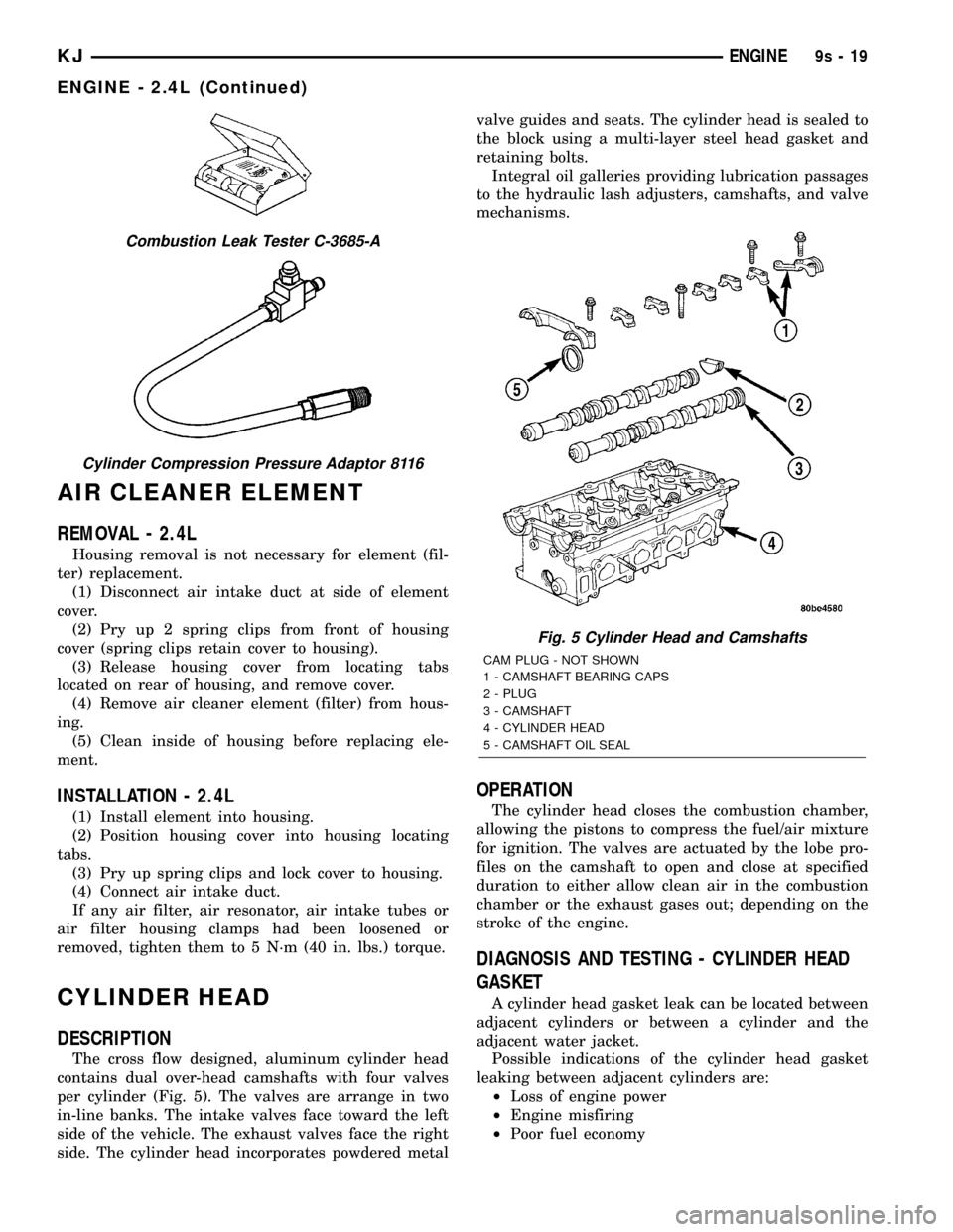
The cross flow designed, aluminum cylinder head
contains dual over-head camshafts with four valves
per cylinder (Fig. 5). The valves are arrange in two
in-line banks. The intake valves face toward the left
side of the vehicle. The exhaust valves face the right
side. The cylinder head incorporates powdered metalvalve guides and seats. The cylinder head is sealed to
the block using a multi-layer steel head gasket and
retaining bolts.
Integral oil galleries providing lubrication passages
to the hydraulic lash adjusters, camshafts, and valve
mechanisms.
OPERATION
The cylinder head closes the combustion chamber,
allowing the pistons to compress the fuel/air mixture
for ignition. The valves are actuated by the lobe pro-
files on the camshaft to open and close at specified
duration to either allow clean air in the combustion
chamber or the exhaust gases out; depending on the
stroke of the engine.
DIAGNOSIS AND TESTING - CYLINDER HEAD
GASKET
A cylinder head gasket leak can be located between
adjacent cylinders or between a cylinder and the
adjacent water jacket.
Possible indications of the cylinder head gasket
leaking between adjacent cylinders are:
²Loss of engine power
²Engine misfiring
²Poor fuel economy
Combustion Leak Tester C-3685-A
Cylinder Compression Pressure Adaptor 8116
Fig. 5 Cylinder Head and Camshafts
CAM PLUG - NOT SHOWN
1 - CAMSHAFT BEARING CAPS
2 - PLUG
3 - CAMSHAFT
4 - CYLINDER HEAD
5 - CAMSHAFT OIL SEAL
KJENGINE9s-19
ENGINE - 2.4L (Continued)
Page 1317 of 1803
Possible indications of the cylinder head gasket
leaking between a cylinder and an adjacent water
jacket are:
²Engine overheating
²Loss of coolant
²Excessive steam (white smoke) emitting from
exhaust
²Coolant foaming
CYLINDER-TO-CYLINDER LEAKAGE TEST
To determine if an engine cylinder head gasket is
leaking between adjacent cylinders, follow the proce-
dures in Cylinder Compression Pressure Test (Refer
to 9 - ENGINE - DIAGNOSIS AND TESTING). An
engine cylinder head gasket leaking between adja-
cent cylinders will result in approximately a 50±70%
reduction in compression pressure.
CYLINDER-TO-WATER JACKET LEAKAGE TEST
WARNING: USE EXTREME CAUTION WHEN THE
ENGINE IS OPERATING WITH COOLANT PRES-
SURE CAP REMOVED.
VISUAL TEST METHOD
With the engine cool, remove the coolant pressure
cap. Start the engine and allow it to warm up until
thermostat opens.
If a large combustion/compression pressure leak
exists, bubbles will be visible in the coolant.
COOLING SYSTEM TESTER METHOD
WARNING: WITH COOLING SYSTEM TESTER IN
PLACE, PRESSURE WILL BUILD UP FAST. EXCES-
SIVE PRESSURE BUILT UP, BY CONTINUOUS
ENGINE OPERATION, MUST BE RELEASED TO A
SAFE PRESSURE POINT. NEVER PERMIT PRES-
SURE TO EXCEED 138 kPa (20 psi).
Install Cooling System Tester 7700 or equivalent to
pressure cap neck. Start the engine and observe the
tester's pressure gauge. If gauge pulsates with every
power stroke of a cylinder a combustion pressure
leak is evident.
CHEMICAL TEST METHOD
Combustion leaks into the cooling system can also
be checked by using Bloc-Chek Kit C-3685-A or
equivalent. Perform test following the procedures
supplied with the tool kit.
REMOVAL - CYLINDER HEAD
(1) Perform fuel system pressure release procedure
before attempting any repairs.(Refer to 14 -FUEL SYSTEM/FUEL DELIVERY - SPECIFICA-
TIONS)
(2) Disconnect battery negative cable.
(3) Drain cooling system. (Refer to 7 - COOLING -
STANDARD PROCEDURE)
(4) Remove air filter housing and inlet tube.
(5) Remove intake manifold.
(6) Remove heater tube support bracket from cyl-
inder head.
(7) Disconnect radiator upper and heater supply
hoses from water outlet connections.
(8) Remove accessory drive belts. (Refer to 7 -
COOLING/ACCESSORY DRIVE/DRIVE BELTS -
REMOVAL)
(9) Raise vehicle and remove exhaust pipe from
manifold.
(10) Remove power steering pump and set aside.
Do not disconnect lines.
(11) Remove accessory drive bracket
(12) Remove ignition coil and wires from engine.
(13) Disconnect cam sensor and fuel injector wir-
ing connectors.
(14) Remove timing belt and camshaft sprockets.
(Refer to 9 - ENGINE/VALVE TIMING/TIMING
BELT/CHAIN AND SPROCKETS - REMOVAL)
(15) Remove timing belt idler pulley and rear tim-
ing belt cover. (Refer to 9 - ENGINE/VALVE TIM-
ING/TIMING BELT / CHAIN COVER(S) -
REMOVAL)
(16) Remove cylinder head cover. (Refer to 9 -
ENGINE/CYLINDER HEAD/CYLINDER HEAD
COVER(S) - REMOVAL)
(17) Remove camshafts (Refer to 9 - ENGINE/
CYLINDER HEAD/CAMSHAFT(S) - REMOVAL).
NOTE: Identify rocker arm position to ensure cor-
rect re-installation in original position, if reused.
(18) Remove rocker arms. (Refer to 9 - ENGINE/
CYLINDER HEAD/ROCKER ARMS - REMOVAL).
(19) Remove cylinder head bolts in REVERSE
sequence of tightening.
(20) Remove cylinder head from engine block.
(21) Inspect and clean cylinder head. (Refer to 9 -
ENGINE/CYLINDER HEAD - INSPECTION) (Refer
to 9 - ENGINE/CYLINDER HEAD - CLEANING)
CLEANING
To ensure engine gasket sealing, proper surface
preparation must be performed, especially with the
use of aluminum engine components and multi-layer
steel cylinder head gaskets.
NOTE: Multi-Layer Steel (MLS) head gaskets require
a scratch free sealing surface.
9s - 20 ENGINEKJ
CYLINDER HEAD (Continued)
Page 1383 of 1803
FUEL SYSTEM
TABLE OF CONTENTS
page page
FUEL DELIVERY..........................1FUEL INJECTION........................29
FUEL DELIVERY
TABLE OF CONTENTS
page page
FUEL DELIVERY
DESCRIPTION..........................2
OPERATION............................3
DIAGNOSIS AND TESTING - FUEL
PRESSURE LEAK DOWN TEST...........3
STANDARD PROCEDURE - FUEL SYSTEM
PRESSURE RELEASE...................4
SPECIFICATIONS
FUEL SYSTEM PRESSURE..............5
TORQUE.............................5
SPECIAL TOOLS
FUEL SYSTEM........................6
FLOW MANAGEMENT VALVE
DESCRIPTION..........................6
OPERATION............................6
REMOVAL.............................6
INSTALLATION..........................7
FUEL FILTER
DESCRIPTION..........................7
REMOVAL.............................7
INSTALLATION..........................8
FUEL LEVEL SENDING UNIT / SENSOR
DESCRIPTION..........................9
OPERATION............................9
DIAGNOSIS AND TESTING - FUEL LEVEL
SENDING UNIT........................9
REMOVAL.............................9
INSTALLATION.........................10
FUEL LINES
DESCRIPTION.........................10
QUICK CONNECT FITTING
DESCRIPTION.........................10
STANDARD PROCEDURE - QUICK-CONNECT
FITTINGS...........................10
FUEL PRESSURE REGULATOR
DESCRIPTION.........................13OPERATION...........................14
REMOVAL.............................14
INSTALLATION.........................14
FUEL PUMP
DESCRIPTION.........................15
OPERATION...........................15
DIAGNOSIS AND TESTING
DIAGNOSIS AND TESTING - FUEL PUMP
CAPACITY TEST......................15
DIAGNOSIS AND TESTING - FUEL PUMP
PRESSURE TEST.....................15
DIAGNOSIS AND TESTING - FUEL PUMP
AMPERAGE TEST.....................16
FUEL PUMP MODULE
DESCRIPTION.........................18
OPERATION...........................18
REMOVAL.............................18
INSTALLATION.........................19
FUEL RAIL
DESCRIPTION.........................21
OPERATION...........................21
REMOVAL.............................22
INSTALLATION.........................24
FUEL TANK
DESCRIPTION.........................24
OPERATION...........................24
REMOVAL.............................25
INSTALLATION.........................27
FUEL TANK CHECK VALVE
DESCRIPTION.........................28
OPERATION...........................28
REMOVAL.............................28
INSTALLATION.........................28
INLET FILTER
REMOVAL.............................28
INSTALLATION.........................28
KJFUEL SYSTEM 14 - 1
Page 1386 of 1803
(8) Pressure should not fall below30 psi for five
minutes.
(9) If pressure falls below 30 psi, it must be deter-
mined if a fuel injector, the check valve within the
fuel pump module, or a fuel tube/line is leaking.
(10) Again, start engine and bring to normal oper-
ating temperature.
(11) Shut engine off.
(12)Testing for fuel injector or fuel rail leak-
age:Clamp off the rubber hose portion of Adaptor
Tool between the fuel rail and the test port ªTº on
Adapter Tool. If pressure now holds at or above 30
psi, a fuel injector or the fuel rail is leaking.
(13)Testing for fuel pump check valve, filter,
regulator check valve or fuel tube/line leakage:
Clamp off the rubber hose portion of Adaptor Tool
between the vehicle fuel line and test port ªTº on
Adapter Tool. If pressure now holds at or above 30
psi, a leak may be found at a fuel tube/line. If no
leaks are found at fuel tubes or lines, one of the
check valves in either the electric fuel pump, fuel fil-
ter or fuel pressure regulator may be leaking.
Note: A quick loss of pressure usually indicates a
defective check valve in the pressure regulator. A
slow loss of pressure usually indicates a defective
check valve in the bottom of the fuel pump module.
The check valves are not serviced separately. Also,
the electric fuel pump is not serviced separately.
STANDARD PROCEDURE - FUEL SYSTEM
PRESSURE RELEASE
Use following procedure if the fuel injector
rail is, or is not equipped with a fuel pressure
test port.
(1) Remove fuel fill cap.
(2) Remove fuel pump relay from Power Distribu-
tion Center (PDC). For location of relay, refer to label
on underside of PDC cover.(3) Start and run engine until it stalls.
(4) Attempt restarting engine until it will no
longer run.
(5) Turn ignition key to OFF position.
CAUTION: Steps 1, 2, 3 and 4 must be performed to
relieve high pressure fuel from within fuel rail. Do
not attempt to use following steps to relieve this
pressure as excessive fuel will be forced into a cyl-
inder chamber.
(6) Unplug connector from any fuel injector.
(7) Attach one end of a jumper wire with alligator
clips (18 gauge or smaller) to either injector terminal.
(8) Connect other end of jumper wire to positive
side of battery.
(9) Connect one end of a second jumper wire to
remaining injector terminal.
CAUTION: Powering an injector for more than a few
seconds will permanently damage the injector.
(10) Momentarily touch other end of jumper wire
to negative terminal of battery for no more than a
few seconds.
(11) Place a rag or towel below fuel line quick-con-
nect fitting at fuel rail.
(12) Disconnect quick-connect fitting at fuel rail.
Refer to Quick-Connect Fittings.
(13) Return fuel pump relay to PDC.
(14) One or more Diagnostic Trouble Codes (DTC's)
may have been stored in PCM memory due to fuel
pump relay removal. The DRBtscan tool must be
used to erase a DTC.
14 - 4 FUEL DELIVERYKJ
FUEL DELIVERY (Continued)