2002 JEEP LIBERTY door panel removal
[x] Cancel search: door panel removalPage 1440 of 1803
KEY-IN IGNITION SWITCH
DESCRIPTION
The key-in ignition switch is integral to the igni-
tion switch, which is mounted on the left side of the
steering column, opposite the ignition lock cylinder.
It closes a path to ground for the instrument cluster
chime warning circuitry when the ignition key is
inserted in the ignition lock cylinder and the driver
door jamb switch is closed (driver door is open). The
key-in ignition switch opens the ground path when
the key is removed from the ignition lock cylinder.
The key-in ignition switch cannot be repaired and,
if faulty or damaged, the entire ignition switch must
be replaced. (Refer to 19 - STEERING/COLUMN/IG-
NITION SWITCH - REMOVAL).
DIAGNOSIS AND TESTING - KEY-IN IGNITION
SWITCH
For circuit descriptions and diagrams, Refer to the
appropriate sections on the individual components.
WARNING: ON VEHICLES EQUIPPED WITH AIR-
BAGS, REFER TO ELECTRICAL - PASSIVE
RESTRAINT SYSTEMS BEFORE ATTEMPTING ANY
STEERING WHEEL, STEERING COLUMN, OR
INSTRUMENT PANEL COMPONENT DIAGNOSIS OR
SERVICE. FAILURE TO TAKE THE PROPER PRE-
CAUTIONS COULD RESULT IN ACCIDENTAL AIR-
BAG DEPLOYMENT AND POSSIBLE PERSONAL
INJURY.
(1) Disconnect and isolate the battery negative
cable. Remove the steering column shrouds. Unplug
the key-in ignition switch wire harness connector
from the ignition switch.
(2) Check for continuity between the key-in switch
sense circuit and the left front door jamb switch
sense circuit terminals of the key-in ignition switch.
There should be continuity with the key in the igni-
tion lock cylinder, and no continuity with the key
removed from the ignition lock cylinder. If OK, go to
Step 3. If not OK, replace the faulty ignition switch
assembly.
(3) Check for continuity between the left front door
jamb switch sense circuit cavity of the key-in ignition
switch wire harness connector and a good ground.
There should be continuity with the driver door open,
and no continuity with the driver door closed. If OK,
see the diagnosis for Instrument Cluster in this
group. If not OK, repair the circuit to the driver door
jamb switch as required.
LOCK CYLINDER
REMOVAL
The ignition key must be in the key cylinder for
cylinder removal. The key cylinder must be removed
first before removing ignition switch.
(1) If equipped with an automatic transmission,
place shifter in PARK position.
(2) Remove the lower shroud cover.
(3) Remove the remote keyless entry (R.K.E.) mod-
ule.
(4) Remove the halo ring around the lock cylinder.
(5) Rotate key to ON position.
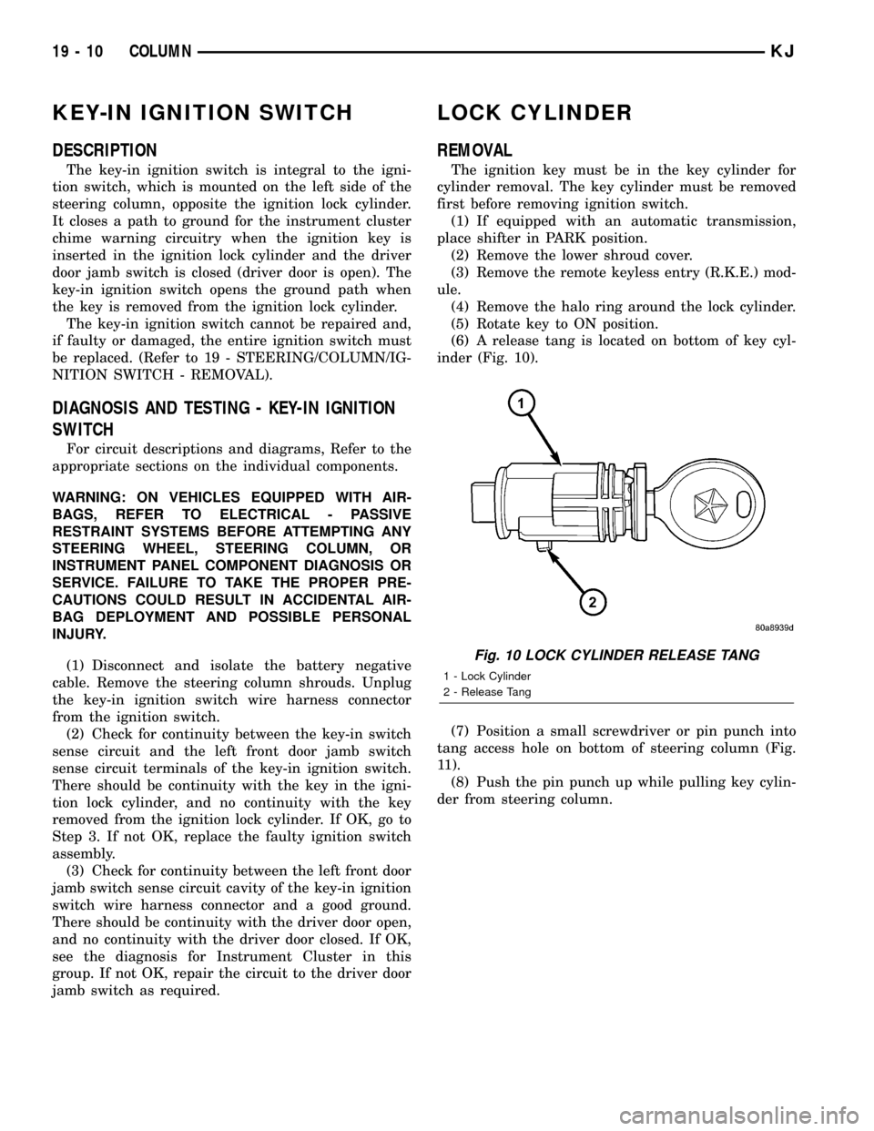
(6) A release tang is located on bottom of key cyl-
inder (Fig. 10).
(7) Position a small screwdriver or pin punch into
tang access hole on bottom of steering column (Fig.
11).
(8) Push the pin punch up while pulling key cylin-
der from steering column.
Fig. 10 LOCK CYLINDER RELEASE TANG
1 - Lock Cylinder
2 - Release Tang
19 - 10 COLUMNKJ
Page 1586 of 1803
DOOR - FRONT
TABLE OF CONTENTS
page page
CHECK STRAP
REMOVAL............................121
INSTALLATION........................121
DOOR
REMOVAL............................122
INSTALLATION........................122
DOOR GLASS
REMOVAL............................122
INSTALLATION........................122
EXTERIOR HANDLE
REMOVAL............................123
INSTALLATION........................123
GLASS RUN CHANNEL
REMOVAL............................123
INSTALLATION........................123
HINGE
REMOVAL............................123
INSTALLATION........................123
LATCH
REMOVAL............................124
INSTALLATION........................124ADJUSTMENTS
ADJUSTMENT.......................124
LATCH STRIKER
REMOVAL............................124
INSTALLATION........................124
LOCK CYLINDER
REMOVAL............................125
INSTALLATION........................125
TRIM PANEL
REMOVAL............................125
INSTALLATION........................126
WATERDAM
REMOVAL............................126
INSTALLATION........................126
WINDOW REGULATOR - MANUAL
REMOVAL............................126
INSTALLATION........................126
WINDOW REGULATOR - ELECTRIC
REMOVAL............................126
INSTALLATION........................126
CHECK STRAP
REMOVAL
(1) Remove the waterdam. (Refer to 23 - BODY/
DOOR - FRONT/WATERDAM - REMOVAL)
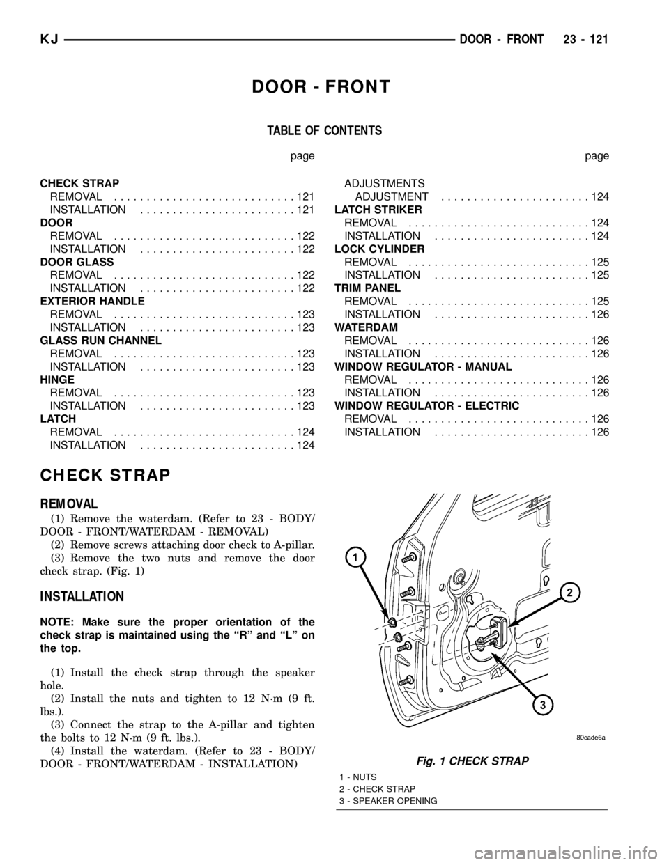
(2) Remove screws attaching door check to A-pillar.
(3) Remove the two nuts and remove the door
check strap. (Fig. 1)
INSTALLATION
NOTE: Make sure the proper orientation of the
check strap is maintained using the ªRº and ªLº on
the top.
(1) Install the check strap through the speaker
hole.
(2) Install the nuts and tighten to 12 N´m (9 ft.
lbs.).
(3) Connect the strap to the A-pillar and tighten
the bolts to 12 N´m (9 ft. lbs.).
(4) Install the waterdam. (Refer to 23 - BODY/
DOOR - FRONT/WATERDAM - INSTALLATION)
Fig. 1 CHECK STRAP
1 - NUTS
2 - CHECK STRAP
3 - SPEAKER OPENING
KJDOOR - FRONT 23 - 121
Page 1590 of 1803
LOCK CYLINDER
REMOVAL
(1) Remove the exterior handle. (Refer to 23 -
BODY/DOOR - FRONT/EXTERIOR HANDLE -
REMOVAL)
(2) Remove the clip and remove the lock cylinder
lever and switch, if equipped.
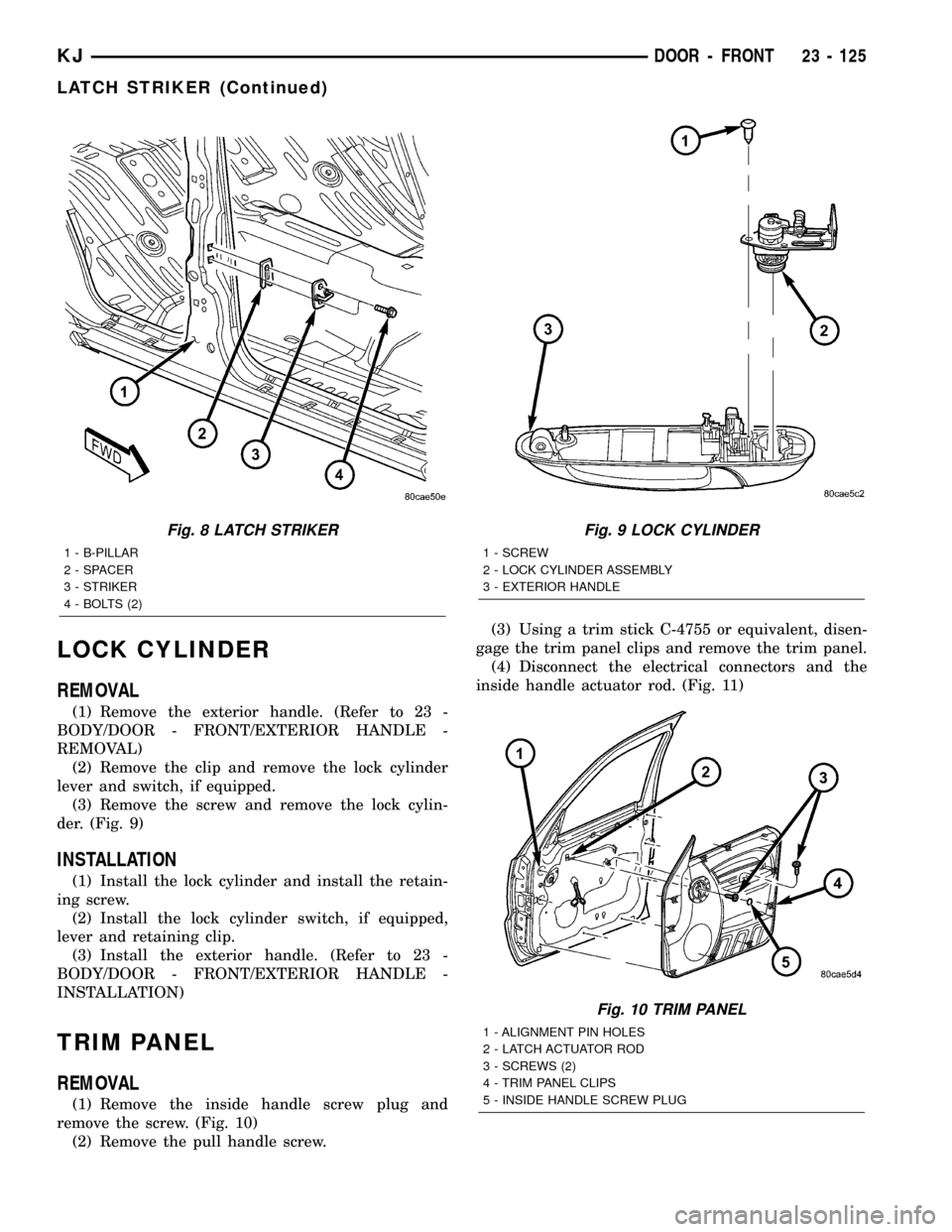
(3) Remove the screw and remove the lock cylin-
der. (Fig. 9)
INSTALLATION
(1) Install the lock cylinder and install the retain-
ing screw.
(2) Install the lock cylinder switch, if equipped,
lever and retaining clip.
(3) Install the exterior handle. (Refer to 23 -
BODY/DOOR - FRONT/EXTERIOR HANDLE -
INSTALLATION)
TRIM PANEL
REMOVAL
(1) Remove the inside handle screw plug and
remove the screw. (Fig. 10)
(2) Remove the pull handle screw.(3) Using a trim stick C-4755 or equivalent, disen-
gage the trim panel clips and remove the trim panel.
(4) Disconnect the electrical connectors and the
inside handle actuator rod. (Fig. 11)
Fig. 8 LATCH STRIKER
1 - B-PILLAR
2 - SPACER
3 - STRIKER
4 - BOLTS (2)
Fig. 9 LOCK CYLINDER
1 - SCREW
2 - LOCK CYLINDER ASSEMBLY
3 - EXTERIOR HANDLE
Fig. 10 TRIM PANEL
1 - ALIGNMENT PIN HOLES
2 - LATCH ACTUATOR ROD
3 - SCREWS (2)
4 - TRIM PANEL CLIPS
5 - INSIDE HANDLE SCREW PLUG
KJDOOR - FRONT 23 - 125
LATCH STRIKER (Continued)
Page 1591 of 1803
INSTALLATION
(1) Connect the inside handle actuator rod and the
electrical connectors.
(2) Position the trim panel and seat the clips fully.
(3) Instal the screws and install the screw plug.
WATERDAM
REMOVAL
(1) Remove the trim panel. (Refer to 23 - BODY/
DOOR - FRONT/TRIM PANEL - REMOVAL)
(2) Remove the door speaker.
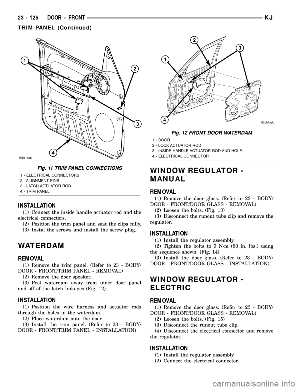
(3) Peal waterdam away from inner door panel
and off of the latch linkages (Fig. 12).
INSTALLATION
(1) Position the wire harness and actuator rods
through the holes in the waterdam.
(2) Place waterdam onto the door.
(3) Install the trim panel. (Refer to 23 - BODY/
DOOR - FRONT/TRIM PANEL - INSTALLATION)
WINDOW REGULATOR -
MANUAL
REMOVAL
(1) Remove the door glass. (Refer to 23 - BODY/
DOOR - FRONT/DOOR GLASS - REMOVAL)
(2) Loosen the bolts. (Fig. 13)
(3) Disconnect the runout tube clip and remove the
regulator.
INSTALLATION
(1) Install the regulator assembly.
(2) Tighten the bolts to 9 N´m (80 in. lbs.) using
the sequence shown. (Fig. 14)
(3) Install the door glass. (Refer to 23 - BODY/
DOOR - FRONT/DOOR GLASS - INSTALLATION)
WINDOW REGULATOR -
ELECTRIC
REMOVAL
(1) Remove the door glass. (Refer to 23 - BODY/
DOOR - FRONT/DOOR GLASS - REMOVAL)
(2) Loosen the bolts. (Fig. 15)
(3) Disconnect the runout tube clip.
(4) Disconnect the electrical connector and remove
the regulator.
INSTALLATION
(1) Install the regulator assembly.
(2) Connect the electrical connector.
Fig. 11 TRIM PANEL CONNECTIONS
1 - ELECTRICAL CONNECTORS
2 - ALIGNMENT PINS
3 - LATCH ACTUATOR ROD
4 - TRIM PANEL
Fig. 12 FRONT DOOR WATERDAM
1 - DOOR
2 - LOCK ACTUATOR ROD
3 - INSIDE HANDLE ACTUATOR ROD AND HOLE
4 - ELECTRICAL CONNECTOR
23 - 126 DOOR - FRONTKJ
TRIM PANEL (Continued)
Page 1593 of 1803
DOORS - REAR
TABLE OF CONTENTS
page page
CHECK STRAP
REMOVAL............................128
INSTALLATION........................128
DOOR
REMOVAL............................129
INSTALLATION........................129
DOOR GLASS
REMOVAL............................129
INSTALLATION........................129
EXTERIOR HANDLE
REMOVAL............................130
INSTALLATION........................130
GLASS RUN CHANNEL
REMOVAL............................130
INSTALLATION........................130
HINGE
REMOVAL............................131
INSTALLATION........................131
LATCH
REMOVAL............................131INSTALLATION........................131
ADJUSTMENTS
ADJUSTMENT.......................131
LATCH STRIKER
REMOVAL............................132
INSTALLATION........................132
TRIM PANEL
REMOVAL............................132
INSTALLATION........................132
WATERDAM
REMOVAL............................133
INSTALLATION........................133
WINDOW REGULATOR - MANUAL
REMOVAL............................133
INSTALLATION........................133
WINDOW REGULATOR - ELECTRIC
REMOVAL............................134
INSTALLATION........................134
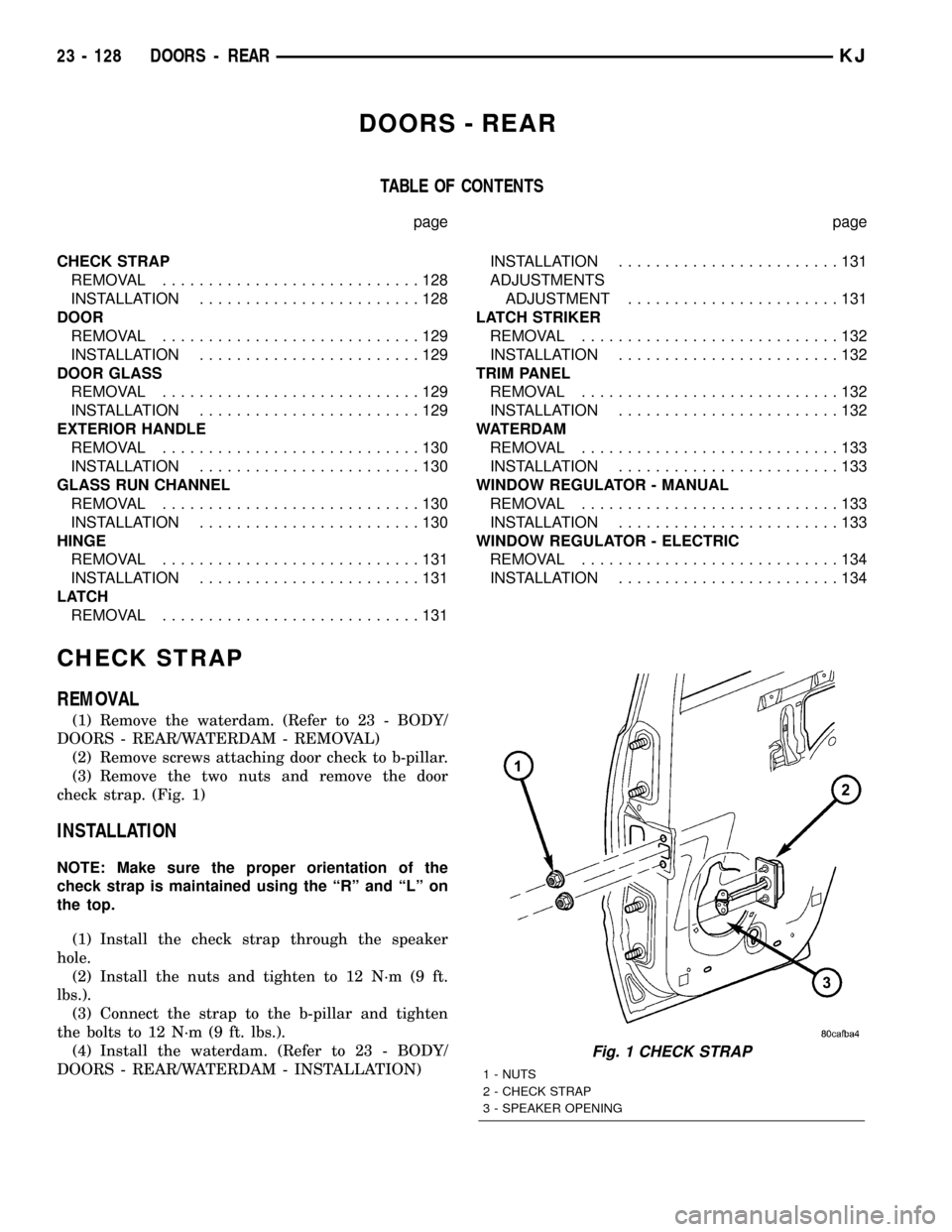
CHECK STRAP
REMOVAL
(1) Remove the waterdam. (Refer to 23 - BODY/
DOORS - REAR/WATERDAM - REMOVAL)
(2) Remove screws attaching door check to b-pillar.
(3) Remove the two nuts and remove the door
check strap. (Fig. 1)
INSTALLATION
NOTE: Make sure the proper orientation of the
check strap is maintained using the ªRº and ªLº on
the top.
(1) Install the check strap through the speaker
hole.
(2) Install the nuts and tighten to 12 N´m (9 ft.
lbs.).
(3) Connect the strap to the b-pillar and tighten
the bolts to 12 N´m (9 ft. lbs.).
(4) Install the waterdam. (Refer to 23 - BODY/
DOORS - REAR/WATERDAM - INSTALLATION)
Fig. 1 CHECK STRAP
1 - NUTS
2 - CHECK STRAP
3 - SPEAKER OPENING
23 - 128 DOORS - REARKJ
Page 1594 of 1803
DOOR
REMOVAL
(1) Disconnect the door wire harness electrical con-
nector at the b-pillar.
(2) Disconnect the check strap from the b-pillar.
(Refer to 23 - BODY/DOORS - REAR/CHECK STRAP
- REMOVAL)
(3) Support the door with a suitable lifting device.
NOTE: The epoxy washers should not be removed
from the hinge. If the washers are removed the door
may have to be re-adjusted.
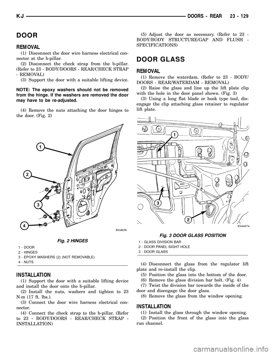
(4) Remove the nuts attaching the door hinges to
the door. (Fig. 2)
INSTALLATION
(1) Support the door with a suitable lifting device
and install the door onto the b-pillar.
(2) Install the nuts, washers and tighten to 23
N´m (17 ft. lbs.).
(3) Connect the door wire harness electrical con-
nector.
(4) Connect the check strap to the b-pillar. (Refer
to 23 - BODY/DOORS - REAR/CHECK STRAP -
INSTALLATION)(5) Adjust the door as necessary. (Refer to 23 -
BODY/BODY STRUCTURE/GAP AND FLUSH -
SPECIFICATIONS)
DOOR GLASS
REMOVAL
(1) Remove the waterdam. (Refer to 23 - BODY/
DOORS - REAR/WATERDAM - REMOVAL)
(2) Raise the glass and line up the lift plate clip
with the hole in the door panel shown. (Fig. 3)
(3) Using a long flat blade or hook type tool, dis-
engage the clip attaching glass retainer to regulator
lift plate.
(4) Disconnect the glass from the regulator lift
plate and re-install the clip.
(5) Position the glass into the bottom of the door.
(6) Remove the glass division bar bolt. (Fig. 4)
(7) Twist the division bar towards the inside of the
door and disengage the door glass.
(8) Remove the glass from the window opening.
INSTALLATION
(1) Install the glass through the window opening.
(2) Position the front of the glass into the glass
run channel.
Fig. 2 HINGES
1 - DOOR
2 - HINGES
3 - EPOXY WASHERS (2) (NOT REMOVABLE)
4 - NUTS
Fig. 3 DOOR GLASS POSITION
1 - GLASS DIVISION BAR
2 - DOOR PANEL SIGHT HOLE
3 - DOOR GLASS
KJDOORS - REAR 23 - 129
Page 1597 of 1803
LATCH STRIKER
REMOVAL
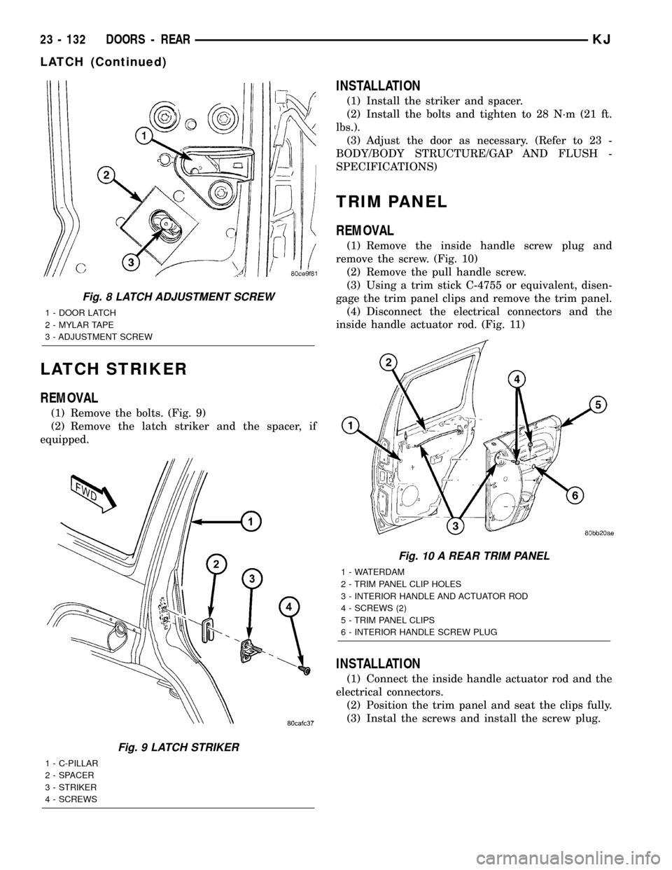
(1) Remove the bolts. (Fig. 9)
(2) Remove the latch striker and the spacer, if
equipped.
INSTALLATION
(1) Install the striker and spacer.
(2) Install the bolts and tighten to 28 N´m (21 ft.
lbs.).
(3) Adjust the door as necessary. (Refer to 23 -
BODY/BODY STRUCTURE/GAP AND FLUSH -
SPECIFICATIONS)
TRIM PANEL
REMOVAL
(1) Remove the inside handle screw plug and
remove the screw. (Fig. 10)
(2) Remove the pull handle screw.
(3) Using a trim stick C-4755 or equivalent, disen-
gage the trim panel clips and remove the trim panel.
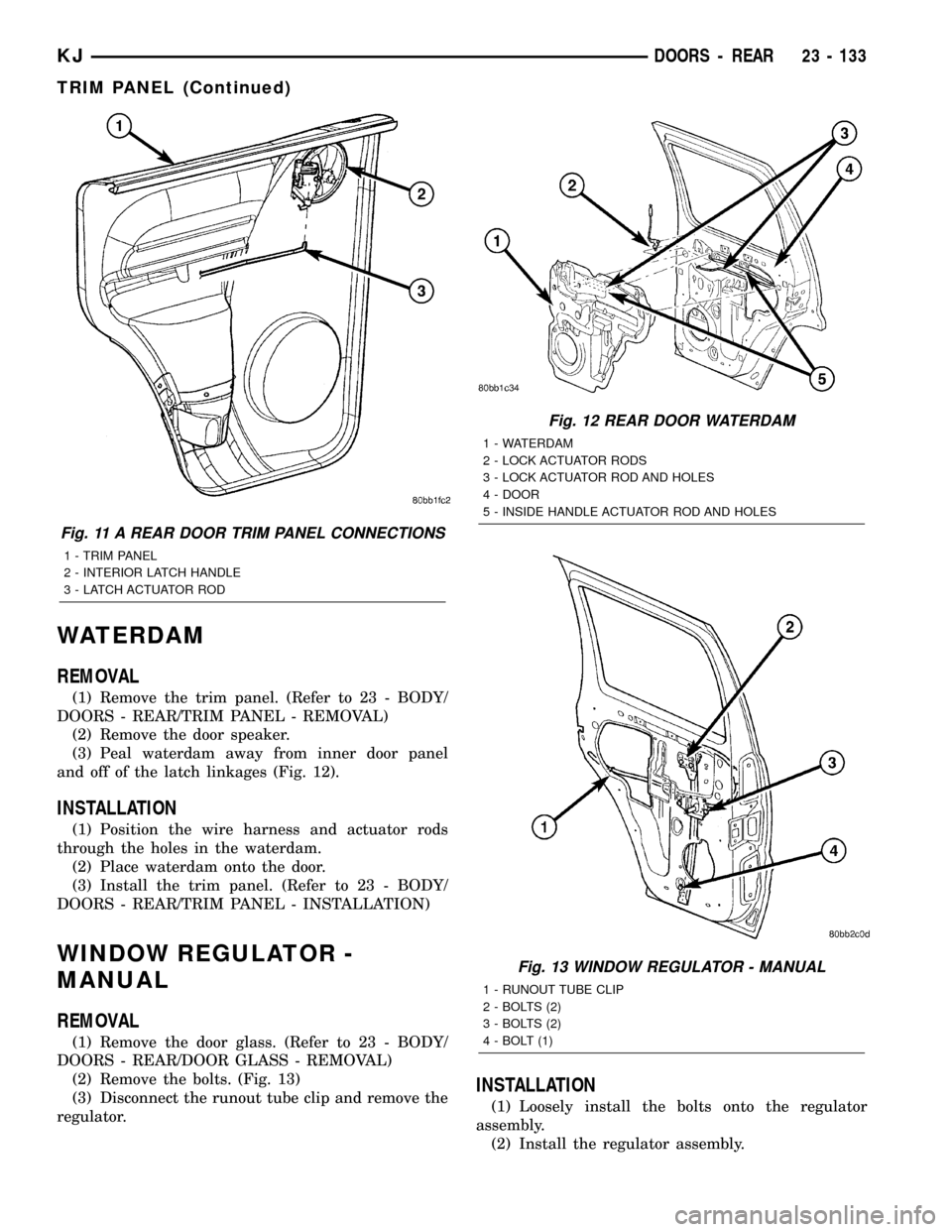
(4) Disconnect the electrical connectors and the
inside handle actuator rod. (Fig. 11)
INSTALLATION
(1) Connect the inside handle actuator rod and the
electrical connectors.
(2) Position the trim panel and seat the clips fully.
(3) Instal the screws and install the screw plug.
Fig. 8 LATCH ADJUSTMENT SCREW
1 - DOOR LATCH
2 - MYLAR TAPE
3 - ADJUSTMENT SCREW
Fig. 9 LATCH STRIKER
1 - C-PILLAR
2 - SPACER
3 - STRIKER
4 - SCREWS
Fig. 10 A REAR TRIM PANEL
1 - WATERDAM
2 - TRIM PANEL CLIP HOLES
3 - INTERIOR HANDLE AND ACTUATOR ROD
4 - SCREWS (2)
5 - TRIM PANEL CLIPS
6 - INTERIOR HANDLE SCREW PLUG
23 - 132 DOORS - REARKJ
LATCH (Continued)
Page 1598 of 1803
WATERDAM
REMOVAL
(1) Remove the trim panel. (Refer to 23 - BODY/
DOORS - REAR/TRIM PANEL - REMOVAL)
(2) Remove the door speaker.
(3) Peal waterdam away from inner door panel
and off of the latch linkages (Fig. 12).
INSTALLATION
(1) Position the wire harness and actuator rods
through the holes in the waterdam.
(2) Place waterdam onto the door.
(3) Install the trim panel. (Refer to 23 - BODY/
DOORS - REAR/TRIM PANEL - INSTALLATION)
WINDOW REGULATOR -
MANUAL
REMOVAL
(1) Remove the door glass. (Refer to 23 - BODY/
DOORS - REAR/DOOR GLASS - REMOVAL)
(2) Remove the bolts. (Fig. 13)
(3) Disconnect the runout tube clip and remove the
regulator.
INSTALLATION
(1) Loosely install the bolts onto the regulator
assembly.
(2) Install the regulator assembly.
Fig. 11 A REAR DOOR TRIM PANEL CONNECTIONS
1 - TRIM PANEL
2 - INTERIOR LATCH HANDLE
3 - LATCH ACTUATOR ROD
Fig. 12 REAR DOOR WATERDAM
1 - WATERDAM
2 - LOCK ACTUATOR RODS
3 - LOCK ACTUATOR ROD AND HOLES
4 - DOOR
5 - INSIDE HANDLE ACTUATOR ROD AND HOLES
Fig. 13 WINDOW REGULATOR - MANUAL
1 - RUNOUT TUBE CLIP
2 - BOLTS (2)
3 - BOLTS (2)
4 - BOLT (1)
KJDOORS - REAR 23 - 133
TRIM PANEL (Continued)