Page 1166 of 1803

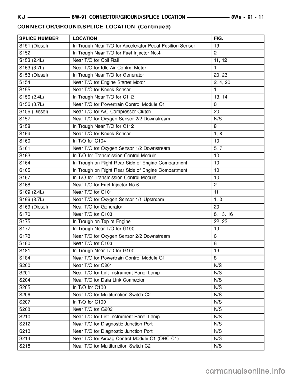
SPLICE NUMBER LOCATION FIG.
S151 (Diesel) In Trough Near T/O for Accelerator Pedal Position Sensor 19
S152 In Trough Near T/O for Fuel Injector No.4 2
S153 (2.4L) Near T/O for Coil Rail 11, 12
S153 (3.7L) Near T/O for Idle Air Control Motor 1
S153 (Diesel) In Trough Near T/O for Generator 20, 23
S154 Near T/O for Engine Starter Motor 2, 4, 20
S155 Near T/O for Knock Sensor 1
S156 (2.4L) In Trough Near T/O for C112 13, 14
S156 (3.7L) Near T/O for Powertrain Control Module C1 8
S156 (Diesel) Near T/O for A/C Compressor Clutch 20
S157 Near T/O for Oxygen Sensor 2/2 Downstream N/S
S158 In Trough Near T/O for C112 8
S159 Near T/O for Knock Sensor 1, 8
S160 In T/O for C104 10
S161 Near T/O for Oxygen Sensor 1/2 Downstream 5, 7
S163 In T/O for Transmission Control Module 10
S164 In Trough on Right Rear Side of Engine Compartment 10
S165 In Trough on Right Rear Side of Engine Compartment 10
S167 In T/O for Transmission Control Module 10
S168 Near T/O for Fuel Injector No.6 2
S169 (2.4L) Near T/O for C101 11
S169 (3.7L) Near T/O for Oxygen Sensor 1/1 Upstream 1, 3
S169 (Diesel) Near T/O for Generator 20
S170 Near T/O for C103 8, 13, 16
S175 In Trough on Top of Engine 22, 23
S177 In Trough Near T/O for G100 19
S178 Near T/O for Oxygen Sensor 2/2 Downstream 6
S180 Near T/O for C103 8
S181 In Trough Near T/O for G100 19
S184 Near T/O for Powertrain Control Module C1 8
S200 Near T/O for C201 N/S
S201 Near T/O for Left Instrument Panel Lamp N/S
S204 Near T/O for Data Link Connector N/S
S205 In T/O for C100 N/S
S206 Near T/O for Multifunction Switch C2 N/S
S207 In T/O for C100 N/S
S208 Near T/O for G202 N/S
S210 Near T/O for Left Instrument Panel Lamp N/S
S212 Near T/O for Diagnostic Junction Port N/S
S213 Near T/O for Diagnostic Junction Port N/S
S214 Near T/O for Airbag Control Module C1 (ORC C1) N/S
S215 Near T/O for Multifunction Switch C2 N/S
KJ8W-91 CONNECTOR/GROUND/SPLICE LOCATION8Wa-91-11
CONNECTOR/GROUND/SPLICE LOCATION (Continued)
Page 1173 of 1803
Fig. 5 LEFT SIDE TRANSMISSION, 3.7L
8Wa - 91 - 18 8W-91 CONNECTOR/GROUND/SPLICE LOCATIONKJ
CONNECTOR/GROUND/SPLICE LOCATION (Continued)
Page 1174 of 1803
Fig. 6 RIGHT SIDE TRANSMISSION, 3.7L
KJ8W-91 CONNECTOR/GROUND/SPLICE LOCATION8Wa-91-19
CONNECTOR/GROUND/SPLICE LOCATION (Continued)
Page 1175 of 1803
Fig. 7 MANUAL TRANSMISSION, 3.7L
8Wa - 91 - 20 8W-91 CONNECTOR/GROUND/SPLICE LOCATIONKJ
CONNECTOR/GROUND/SPLICE LOCATION (Continued)
Page 1179 of 1803
Fig. 11 ENGINE/TRANSMISSION, 2.4L
8Wa - 91 - 24 8W-91 CONNECTOR/GROUND/SPLICE LOCATIONKJ
CONNECTOR/GROUND/SPLICE LOCATION (Continued)
Page 1180 of 1803
Fig. 12 ENGINE/TRANSMISSION, 2.4L
KJ8W-91 CONNECTOR/GROUND/SPLICE LOCATION8Wa-91-25
CONNECTOR/GROUND/SPLICE LOCATION (Continued)
Page 1226 of 1803

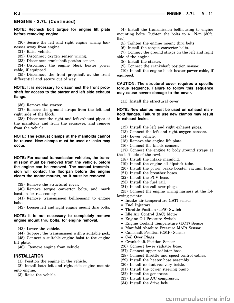
NOTE: Recheck bolt torque for engine lift plate
before removing engine.
(30) Secure the left and right engine wiring har-
nesses away from engine.
(31) Raise vehicle.
(32) Disconnect oxygen sensor wiring.
(33) Disconnect crankshaft postion sensor.
(34) Disconnect the engine block heater power
cable, if equipped.
(35) Disconnect the front propshaft at the front
differential and secure out of way.
NOTE: It is necessary to disconnect the front prop-
shaft for access to the starter and left side exhaust
flange.
(36) Remove the starter.
(37) Remove the ground straps from the left and
right side of the block.
(38) Disconnect the right and left exhaust pipes at
the manifolds and from the crossover, and remove
from the vehicle.
NOTE: The exhaust clamps at the manifolds cannot
be reused. New clamps must be used or leaks may
occur.
NOTE: For manual transmission vehicles, the trans-
mission must be removed from the vehicle, before
the engine can be removed. The manual transmis-
sion will contact the floorpan before the engine
clears the motor mounts, so it must be removed.
(39) Remove the structural cover.
(40) Remove torque convertor bolts, and mark
location for reassembly.
(41) Remove transmission bellhousing to engine
bolts.
(42) Loosen left and right engine mount thru bolts.
NOTE: It is not necessary to completely remove
engine mount thru bolts, for engine removal.
(43) Lower the vehicle.
(44) Support the transmission with a suitable jack.
(45) Connect a suitable engine hoist to the engine
lift plate.
(46) Remove engine from vehicle.
INSTALLATION
(1) Position the engine in the vehicle.
(2) Install both left and right side engine mounts
onto engine.
(3) Raise the vehicle.(4) Install the transmission bellhousing to engine
mounting bolts. Tighten the bolts to 41 N´m (30ft.
lbs.).
(5) Tighten the engine mount thru bolts.
(6) Install the torque convertor bolts.
(7) Connect the ground straps on the left and right
side of the engine.
(8) Install the starter.
(9) Connect the crankshaft position sensor.
(10) Install the engine block heater power cable, if
equipped.
CAUTION: The structural cover requires a specific
torque sequence. Failure to follow this sequence
may cause severe damage to the cover.
(11) Install the structural cover.
NOTE: New clamps must be used on exhaust man-
ifold flanges. Failure to use new clamps may result
in exhaust leaks.
(12) Install the left and right exhaust pipes.
(13) Connect the left and right oxygen sensors.
(14) Lower vehicle.
(15) Remove the engine lift plate.
(16) Connect the knock sensors.
(17) Connect the engine to body ground straps at
the left side of the cowl.
(18) Install the intake manifold.
(19) Install the engine oil dipstick tube.
(20) Install the power brake booster vacuum hose.
(21) Install the breather hoses.
(22) Install the PCV hose.
(23) Install the fuel rail.
(24) Install the coil over plugs.
(25) Connect the engine wiring harness at the fol-
lowing points:
²Intake air temperature (IAT) sensor
²Fuel Injectors
²Throttle Position (TPS) Switch
²Idle Air Control (IAC) Motor
²Engine Oil Pressure Switch
²Engine Coolant Temperature (ECT) Sensor
²Manifold Absolute Pressure MAP) Sensor
²Camshaft Position (CMP) Sensor
²Coil Over Plugs
²Crankshaft Position Sensor
(26) Connect lower radiator hose.
(27) Connect upper radiator hose.
(28) Connect throttle and speed control cables.
(29) Install the heater hose assembly.
(30) Install coolant recovery bottle.
(31) Install the power steering pump.
(32) Install the generator.
(33) Install the A/C compressor.
(34) Install the drive belt.
KJENGINE - 3.7L 9 - 11
ENGINE - 3.7L (Continued)
Page 1227 of 1803

(35) Install the mechanical cooling fan.
(36) Install the fan shroud with the electric fan
assembly.
(37) Install the radiator core support bracket.
(38) Install the air cleaner assembly.
(39) Refill the engine cooling system.
(40) Install the hood.
(41) Check and fill engine oil.
(42) Connect the battery negative cable.
(43) Start the engine and check for leaks.
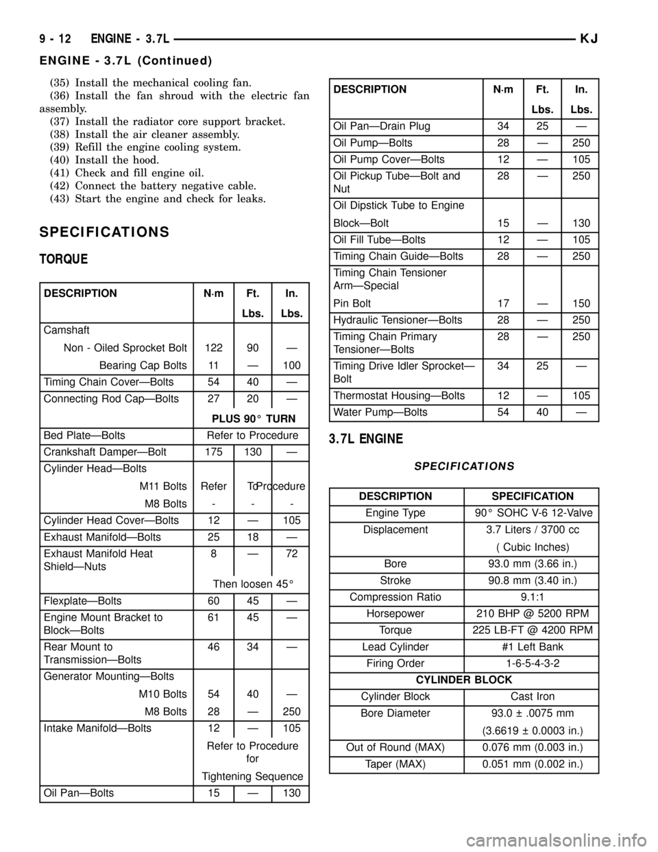
SPECIFICATIONS
TORQUE
DESCRIPTION N´m Ft. In.
Lbs. Lbs.
Camshaft
Non - Oiled Sprocket Bolt 122 90 Ð
Bearing Cap Bolts 11 Ð 100
Timing Chain CoverÐBolts 54 40 Ð
Connecting Rod CapÐBolts 27 20 Ð
PLUS 90É TURN
Bed PlateÐBolts Refer to Procedure
Crankshaft DamperÐBolt 175 130 Ð
Cylinder HeadÐBolts
M11 Bolts Refer ToProcedure
M8 Bolts - - -
Cylinder Head CoverÐBolts 12 Ð 105
Exhaust ManifoldÐBolts 25 18 Ð
Exhaust Manifold Heat
ShieldÐNuts8Ð72
Then loosen 45É
FlexplateÐBolts 60 45 Ð
Engine Mount Bracket to
BlockÐBolts61 45 Ð
Rear Mount to
TransmissionÐBolts46 34 Ð
Generator MountingÐBolts
M10 Bolts 54 40 Ð
M8 Bolts 28 Ð 250
Intake ManifoldÐBolts 12 Ð 105
Refer to Procedure
for
Tightening Sequence
Oil PanÐBolts 15 Ð 130
DESCRIPTION N´m Ft. In.
Lbs. Lbs.
Oil PanÐDrain Plug 34 25 Ð
Oil PumpÐBolts 28 Ð 250
Oil Pump CoverÐBolts 12 Ð 105
Oil Pickup TubeÐBolt and
Nut28 Ð 250
Oil Dipstick Tube to Engine
BlockÐBolt 15 Ð 130
Oil Fill TubeÐBolts 12 Ð 105
Timing Chain GuideÐBolts 28 Ð 250
Timing Chain Tensioner
ArmÐSpecial
Pin Bolt 17 Ð 150
Hydraulic TensionerÐBolts 28 Ð 250
Timing Chain Primary
TensionerÐBolts28 Ð 250
Timing Drive Idler SprocketÐ
Bolt34 25 Ð
Thermostat HousingÐBolts 12 Ð 105
Water PumpÐBolts 54 40 Ð
3.7L ENGINE
SPECIFICATIONS
DESCRIPTION SPECIFICATION
Engine Type 90É SOHC V-6 12-Valve
Displacement 3.7 Liters / 3700 cc
( Cubic Inches)
Bore 93.0 mm (3.66 in.)
Stroke 90.8 mm (3.40 in.)
Compression Ratio 9.1:1
Horsepower 210 BHP @ 5200 RPM
Torque 225 LB-FT @ 4200 RPM
Lead Cylinder #1 Left Bank
Firing Order 1-6-5-4-3-2
CYLINDER BLOCK
Cylinder Block Cast Iron
Bore Diameter 93.0 .0075 mm
(3.6619 0.0003 in.)
Out of Round (MAX) 0.076 mm (0.003 in.)
Taper (MAX) 0.051 mm (0.002 in.)
9 - 12 ENGINE - 3.7LKJ
ENGINE - 3.7L (Continued)