2002 JEEP LIBERTY motor parts
[x] Cancel search: motor partsPage 19 of 1803

towing device, use tow dollies under the opposite end
of the vehicle. A vehicle with flatbed device can also
be used to transport a disabled vehicle (Fig. 6).
SAFETY PRECAUTIONS
CAUTION: The following safety precautions must be
observed when towing a vehicle:
²Secure loose and protruding parts.
²Always use a safety chain system that is inde-
pendent of the lifting and towing equipment.
²Do not allow towing equipment to contact the
disabled vehicle's fuel tank.
²Do not allow anyone under the disabled vehicle
while it is lifted by the towing device.
²Do not allow passengers to ride in a vehicle
being towed.
²Always observe state and local laws regarding
towing regulations.
²Do not tow a vehicle in a manner that could
jeopardize the safety of the operator, pedestrians or
other motorists.
²Do not attach tow chains, T-hooks, or J-hooks to
a bumper, steering linkage, drive shafts or a non-re-
inforced frame hole.
²Do not tow a heavily loaded vehicle. Use a flat-
bed device to transport a loaded vehicle.
TWO-WHEEL-DRIVE VEHICLE TOWING
DaimlerChrysler Corporation recommends that a
vehicle be towed with the rear end lifted, whenever
possible.
WARNING: WHEN TOWING A DISABLED VEHICLE
AND THE DRIVE WHEELS ARE SECURED IN A
WHEEL LIFT OR TOW DOLLIES, ENSURE THE
TRANSMISSION IS IN THE PARK POSITION (AUTO-
MATIC TRANSMISSION) OR A FORWARD DRIVE
GEAR (MANUAL TRANSMISSION).WARNING: ENSURE VEHICLE IS ON A LEVEL SUR-
FACE OR THE WHEELS ARE BLOCKED TO PRE-
VENT VEHICLE FROM ROLLING.
TWO WHEEL DRIVE TOWING-REAR END LIFTED
CAUTION: Do not use steering column lock to
secure steering wheel during towing operation.
2WD vehicles can be towed with the front wheels
on the surface for extended distances at speeds not
exceeding 48 km/h (30 mph).
(1) Attach wheel lift device to rear wheels.
(2) Place the transmission in neutral.
(3) Raise vehicle to towing position.
(4) Attach safety chains. Route chains so not to
interfere with tail pipe when vehicle is lifted.
(5) Turn the ignition switch to the OFF position to
unlock the steering wheel.
CAUTION: Do not use steering column lock to
secure steering wheel during towing operation.
(6) Secure steering wheel in straight ahead posi-
tion with a clamp device designed for towing.
(7) Place transmission in park.
TWO WHEEL DRIVE TOWING-FRONT END LIFTED
CAUTION: Many vehicles are equipped with air
dams, spoilers, and/or ground effect panels. To
avoid component damage, a wheel-lift towing vehi-
cle or a flat-bed hauling vehicle is recommended.
(1) Attach wheel lift device to rear wheels.
(2) Place the transmission in neutral.
(3) Raise the rear of the vehicle off the ground and
install tow dollies under rear wheels.
(4) Attach wheel lift device to front wheels and
raise vehicle to towing position.
(5) Attach the safety chains.
CAUTION: Do not use steering column lock to
secure steering wheel during towing operation.
(6) Turn the ignition switch to the OFF position to
unlock the steering wheel.
(7) Secure steering wheel in straight ahead posi-
tion with a clamp device designed for towing.
(8) Place transmission in park.
FOUR-WHEEL-DRIVE VEHICLE TOWING
DaimlerChrysler Corporation recommends that a
4WD vehicle be transported on a flat-bed device. A
Wheel-lift device can be used providedthe trailing
wheels are off the ground and positioned in
tow dollies.
Fig. 6 Tow Vehicles With Approved Equipment
KJLUBRICATION & MAINTENANCE 0 - 7
TOWING (Continued)
Page 310 of 1803

POWERTRAIN CONTROL
MODULE
DESCRIPTION
DESCRIPTION - PCM
The Powertrain Control Module (PCM) is located
in the engine compartment (Fig. 8). The PCM is
referred to as JTEC.
DESCRIPTION - MODES OF OPERATION
As input signals to the Powertrain Control Module
(PCM) change, the PCM adjusts its response to the
output devices. For example, the PCM must calculate
different injector pulse width and ignition timing for
idle than it does for wide open throttle (WOT).
The PCM will operate in two different modes:
Open Loop and Closed Loop.
During Open Loop modes, the PCM receives input
signals and responds only according to preset PCM
programming. Input from the oxygen (O2S) sensors
is not monitored during Open Loop modes.
During Closed Loop modes, the PCM will monitor
the oxygen (O2S) sensors input. This input indicates
to the PCM whether or not the calculated injector
pulse width results in the ideal air-fuel ratio. This
ratio is 14.7 parts air-to-1 part fuel. By monitoring
the exhaust oxygen content through the O2S sensor,
the PCM can fine tune the injector pulse width. This
is done to achieve optimum fuel economy combined
with low emission engine performance.
The fuel injection system has the following modes
of operation:
²Ignition switch ON
²Engine start-up (crank)
²Engine warm-up
²Idle
²Cruise
²Acceleration
²Deceleration
²Wide open throttle (WOT)
²Ignition switch OFF
The ignition switch On, engine start-up (crank),
engine warm-up, acceleration, deceleration and wide
open throttle modes are Open Loop modes. The idle
and cruise modes, (with the engine at operating tem-
perature) are Closed Loop modes.
IGNITION SWITCH (KEY-ON) MODE
This is an Open Loop mode. When the fuel system
is activated by the ignition switch, the following
actions occur:
²The PCM pre-positions the idle air control (IAC)
motor.
²The PCM determines atmospheric air pressure
from the MAP sensor input to determine basic fuel
strategy.
²The PCM monitors the engine coolant tempera-
ture sensor input. The PCM modifies fuel strategy
based on this input.
²Intake manifold air temperature sensor input is
monitored.
²Throttle position sensor (TPS) is monitored.
²The auto shutdown (ASD) relay is energized by
the PCM for approximately three seconds.
Fig. 7 DATA LINK CONNECTOR LOCATION
Fig. 8 PCM LOCATION
KJELECTRONIC CONTROL MODULES 8E - 11
DATA LINK CONNECTOR (Continued)
Page 711 of 1803

FRONT WASHER HOSES/
TUBES
DESCRIPTION
The front washer plumbing consists of a small
diameter rubber hose that is routed from the barbed
outlet nipple of the reversible electric washer pump/
motor unit on the washer reservoir through a trough
molded into the reservoir forward of the washer
pump and along the reservoir filler neck into the
engine compartment (Fig. 5). Within the engine com-
partment, the front washer hose is routed side by
side with the engine compartment rear washer hose
along the top of the right front fender wheel house to
the dash panel. Molded plastic routing clips secure
the hoses to the headlamp and dash wire harness in
the engine compartment (Fig. 6).
The front washer hose is connected in the engine
compartment to the barbed nipple of a molded plastic
in-line fitting installed through a rubber grommet in
a hole in the right side of the dash plenum panel.
The barbed nipple of the in-line fitting protrudes
through the other side of the rubber grommet into
the cowl plenum area, where the cowl plenum
washer hose joins the front washer hose to the frontcheck valve/wye fitting. The cowl plenum washer
hose is routed through integral routing clips on the
underside of the cowl plenum cover/grille panel to the
molded plastic wye fitting. The cowl plenum washer
hose is connected to one nipple on the wye fitting and
the two washer nozzle hoses are connected to the
other two wye fitting nipples. The washer nozzle
hoses are then routed along the underside of the cowl
plenum cover/grille panel to the two front washer
nozzles.
Washer hose is available for service only as roll
stock, which must then be cut to length. The molded
plastic washer hose fittings cannot be repaired. If
these fittings are faulty or damaged, they must be
replaced.
OPERATION
Washer fluid in the washer reservoir is pressurized
and fed by the washer pump/motor through the front
washer system plumbing and fittings to the two front
washer nozzles. Whenever routing the washer hose
or a wire harness containing a washer hose, it must
be routed away from hot, sharp, or moving parts;
and, sharp bends that might pinch the hose must be
avoided.
Fig. 5 Reservoir Washer Hose
1 - WASHER RESERVOIR
2 - RIGHT FRONT WHEEL HOUSE
3 - WASHER PUMP
4 - FRONT WASHER HOSE
5 - RESERVOIR REAR WASHER HOSE
6 - WASHER FLUID LEVEL SWITCH
Fig. 6 Engine Compartment Washer Hose
1 - RESERVOIR FILLER CAP
2 - ROUTING CLIP (3)
3 - ROUTING CLIP (1)
4 - FRONT WASHER HOSE
5 - IN-LINE HOSE FITTING
6 - PLENUM PANEL GROMMET
7 - DASH PANEL GROMMET
8 - REAR WASHER HEADLINER HOSE
8R - 10 FRONT WIPERS/WASHERSKJ
Page 737 of 1803

headliner hose is glued to top of the headliner and
routed along the right roof side rail to the rear of the
vehicle. At the rear of the vehicle, the headliner hose
passes through a hole at the rear portion of the roof
rear inner header panel and is connected to the rear
check valve. From the rear check valve, there is a
short section of hose that connects the rear check
valve to the rear washer nozzle.
Washer hose is available for service only as roll
stock, which must then be cut to length. The head-
liner washer hose is integral to the headliner unit
and, if faulty or damaged, the headliner unit must be
replaced. However, the headliner hose is marked
with a white cut line on the A-pillar where the hose
should be cut and spliced with a plastic in-line con-
nector fitting to facilitate headliner removal without
the need to remove the instrument panel. (Refer to
23 - BODY/INTERIOR/HEADLINER - REMOVAL
AND INSTALLATION). The molded plastic washer
hose fittings cannot be repaired. If these fittings are
faulty or damaged, they must be replaced.
OPERATION
Washer fluid in the washer reservoir is pressurized
and fed by the washer pump/motor through the rear
washer system plumbing and fittings to the rear
washer nozzle located on the roof panel above the
rear flip-up glass opening. Whenever routing the
washer hose or a wire harness containing a washer
hose, it must be routed away from hot, sharp, or
moving parts; and, sharp bends that might pinch the
hose must be avoided.
REAR WASHER NOZZLE
DESCRIPTION
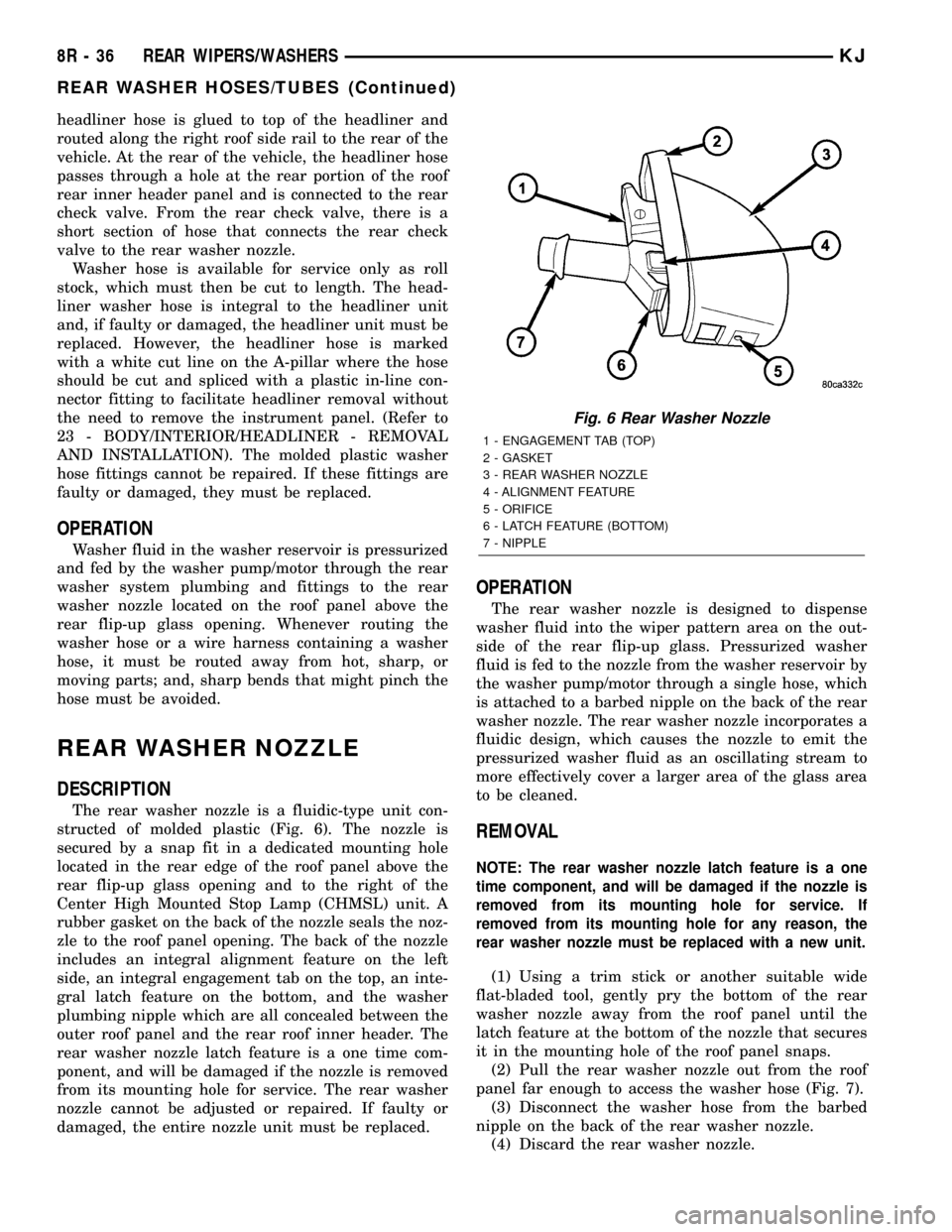
The rear washer nozzle is a fluidic-type unit con-
structed of molded plastic (Fig. 6). The nozzle is
secured by a snap fit in a dedicated mounting hole
located in the rear edge of the roof panel above the
rear flip-up glass opening and to the right of the
Center High Mounted Stop Lamp (CHMSL) unit. A
rubber gasket on the back of the nozzle seals the noz-
zle to the roof panel opening. The back of the nozzle
includes an integral alignment feature on the left
side, an integral engagement tab on the top, an inte-
gral latch feature on the bottom, and the washer
plumbing nipple which are all concealed between the
outer roof panel and the rear roof inner header. The
rear washer nozzle latch feature is a one time com-
ponent, and will be damaged if the nozzle is removed
from its mounting hole for service. The rear washer
nozzle cannot be adjusted or repaired. If faulty or
damaged, the entire nozzle unit must be replaced.
OPERATION
The rear washer nozzle is designed to dispense
washer fluid into the wiper pattern area on the out-
side of the rear flip-up glass. Pressurized washer
fluid is fed to the nozzle from the washer reservoir by
the washer pump/motor through a single hose, which
is attached to a barbed nipple on the back of the rear
washer nozzle. The rear washer nozzle incorporates a
fluidic design, which causes the nozzle to emit the
pressurized washer fluid as an oscillating stream to
more effectively cover a larger area of the glass area
to be cleaned.
REMOVAL
NOTE: The rear washer nozzle latch feature is a one
time component, and will be damaged if the nozzle is
removed from its mounting hole for service. If
removed from its mounting hole for any reason, the
rear washer nozzle must be replaced with a new unit.
(1) Using a trim stick or another suitable wide
flat-bladed tool, gently pry the bottom of the rear
washer nozzle away from the roof panel until the
latch feature at the bottom of the nozzle that secures
it in the mounting hole of the roof panel snaps.
(2) Pull the rear washer nozzle out from the roof
panel far enough to access the washer hose (Fig. 7).
(3) Disconnect the washer hose from the barbed
nipple on the back of the rear washer nozzle.
(4) Discard the rear washer nozzle.
Fig. 6 Rear Washer Nozzle
1 - ENGAGEMENT TAB (TOP)
2 - GASKET
3 - REAR WASHER NOZZLE
4 - ALIGNMENT FEATURE
5 - ORIFICE
6 - LATCH FEATURE (BOTTOM)
7 - NIPPLE
8R - 36 REAR WIPERS/WASHERSKJ
REAR WASHER HOSES/TUBES (Continued)
Page 754 of 1803

WARNING: BE SURE THAT THE IGNITION SWITCH
ALWAYS IS IN THE OFF POSITION, UNLESS THE
PROCEDURE REQUIRES IT TO BE ON.
WARNING: SET THE PARKING BRAKE WHEN
WORKING ON ANY VEHICLE. AN AUTOMATIC
TRANSMISSION SHOULD BE IN PARK. A MANUAL
TRANSMISSION SHOULD BE IN NEUTRAL.
WARNING: OPERATE THE ENGINE ONLY IN A
WELL-VENTILATED AREA.
WARNING: KEEP AWAY FROM MOVING PARTS
WHEN THE ENGINE IS RUNNING, ESPECIALLY THE
FAN AND BELTS.
WARNING: TO PREVENT SERIOUS BURNS, AVOID
CONTACT WITH HOT PARTS SUCH AS THE RADIA-
TOR, EXHAUST MANIFOLD(S), TAIL PIPE, CATA-
LYTIC CONVERTER AND MUFFLER.
WARNING: DO NOT ALLOW FLAME OR SPARKS
NEAR THE BATTERY. GASES ARE ALWAYS
PRESENT IN AND AROUND THE BATTERY.
WARNING: ALWAYS REMOVE RINGS, WATCHES,
LOOSE HANGING JEWELRY AND AVOID LOOSE
CLOTHING.
DIAGNOSIS AND TESTING - WIRING HARNESS
TROUBLESHOOTING TOOLS
When diagnosing a problem in an electrical circuit
there are several common tools necessary. These tools
are listed and explained below.
²Jumper Wire - This is a test wire used to con-
nect two points of a circuit. It can be used to bypass
an open in a circuit.
WARNING: NEVER USE A JUMPER WIRE ACROSS
A LOAD, SUCH AS A MOTOR, CONNECTED
BETWEEN A BATTERY FEED AND GROUND.
²Voltmeter - Used to check for voltage on a cir-
cuit. Always connect the black lead to a known good
ground and the red lead to the positive side of the
circuit.
CAUTION: Most of the electrical components used
in today's vehicles are Solid State. When checking
voltages in these circuits, use a meter with a 10 -
megohm or greater impedance rating.²Ohmmeter - Used to check the resistance
between two points of a circuit. Low or no resistance
in a circuit means good continuity.
CAUTION: Most of the electrical components used
in today's vehicles are Solid State. When checking
resistance in these circuits use a meter with a 10 -
megohm or greater impedance rating. In addition,
make sure the power is disconnected from the cir-
cuit. Circuits that are powered up by the vehicle's
electrical system can cause damage to the equip-
ment and provide false readings.
²Probing Tools - These tools are used for probing
terminals in connectors (Fig. 5). Select the proper
size tool from Special Tool Package 6807, and insert
it into the terminal being tested. Use the other end
of the tool to insert the meter probe.
INTERMITTENT AND POOR CONNECTIONS
Most intermittent electrical problems are caused
by faulty electrical connections or wiring. It is also
possible for a sticking component or relay to cause a
problem. Before condemning a component or wiring
assembly, check the following items.
²Connectors are fully seated
²Spread terminals, or terminal push out
²Terminals in the wiring assembly are fully
seated into the connector/component and locked into
position
²Dirt or corrosion on the terminals. Any amount
of corrosion or dirt could cause an intermittent prob-
lem
²Damaged connector/component casing exposing
the item to dirt or moisture
²Wire insulation that has rubbed through causing
a short to ground
²Some or all of the wiring strands broken inside
of the insulation
²Wiring broken inside of the insulation
Fig. 5 PROBING TOOL
1 - SPECIAL TOOL 6801
2 - PROBING END
KJ8W-01 WIRING DIAGRAM INFORMATION8Wa-01-7
WIRING DIAGRAM INFORMATION (Continued)
Page 1254 of 1803

ENGINE BLOCK
DESCRIPTION
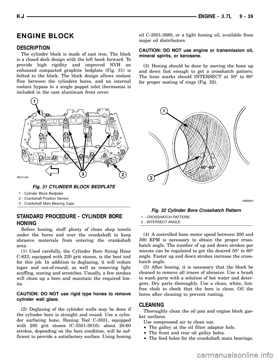
The cylinder block is made of cast iron. The block
is a closed deck design with the left bank forward. To
provide high rigidity and improved NVH an
enhanced compacted graphite bedplate (Fig. 31) is
bolted to the block. The block design allows coolant
flow between the cylinders bores, and an internal
coolant bypass to a single poppet inlet thermostat is
included in the cast aluminum front cover.
STANDARD PROCEDURE - CYLINDER BORE
HONING
Before honing, stuff plenty of clean shop towels
under the bores and over the crankshaft to keep
abrasive materials from entering the crankshaft
area.
(1) Used carefully, the Cylinder Bore Sizing Hone
C-823, equipped with 220 grit stones, is the best tool
for this job. In addition to deglazing, it will reduce
taper and out-of-round, as well as removing light
scuffing, scoring and scratches. Usually, a few strokes
will clean up a bore and maintain the required lim-
its.
CAUTION: DO NOT use rigid type hones to remove
cylinder wall glaze.
(2) Deglazing of the cylinder walls may be done if
the cylinder bore is straight and round. Use a cylin-
der surfacing hone, Honing Tool C-3501, equipped
with 280 grit stones (C-3501-3810). about 20-60
strokes, depending on the bore condition, will be suf-
ficient to provide a satisfactory surface. Using honingoil C-3501-3880, or a light honing oil, available from
major oil distributors.
CAUTION: DO NOT use engine or transmission oil,
mineral spirits, or kerosene.
(3) Honing should be done by moving the hone up
and down fast enough to get a crosshatch pattern.
The hone marks should INTERSECT at 50É to 60É
for proper seating of rings (Fig. 32).
(4) A controlled hone motor speed between 200 and
300 RPM is necessary to obtain the proper cross-
hatch angle. The number of up and down strokes per
minute can be regulated to get the desired 50É to 60É
angle. Faster up and down strokes increase the cross-
hatch angle.
(5) After honing, it is necessary that the block be
cleaned to remove all traces of abrasive. Use a brush
to wash parts with a solution of hot water and deter-
gent. Dry parts thoroughly. Use a clean, white, lint-
free cloth to check that the bore is clean. Oil the
bores after cleaning to prevent rusting.
CLEANING
Thoroughly clean the oil pan and engine block gas-
ket surfaces.
Use compressed air to clean out:
²The galley at the oil filter adaptor hole.
²The front and rear oil galley holes.
²The feed holes for the crankshaft main bearings.
Fig. 31 CYLINDER BLOCK BEDPLATE
1 - Cylinder Block Bedplate
2 - Crankshaft Position Sensor
3 - Crankshaft Main Bearing Caps
Fig. 32 Cylinder Bore Crosshatch Pattern
1 - CROSSHATCH PATTERN
2 - INTERSECT ANGLE
KJENGINE - 3.7L 9 - 39
Page 1306 of 1803

CONDITION POSSIBLE CAUSES CORRECTION
OIL CONSUMPTION OR SPARK
PLUGS FOULED1. PCV system malfunction. 1. Check system and repair as
necessary. (Refer to 25 -
EMISSIONS CONTROL/
EVAPORATIVE EMISSIONS/PCV
VALVE - DIAGNOSIS AND
TESTING)
2. Worn, scuffed or broken rings. 2. Hone cylinder bores. Install new
rings.
3. Carbon in oil ring slots. 3. Install new rings.
4. Rings fitted too tightly in grooves. 4. Remove rings and check
grooves. If groove is not proper
width, replace piston.
5. Worn valve guide(s). 5. Replace cylinder head assembly.
6. Valve stem seal(s) worn or
damaged.6. Replace seal(s).
STANDARD PROCEDURE
STANDARD PROCEDURE - ENGINE CORE AND
OIL GALLERY PLUGS
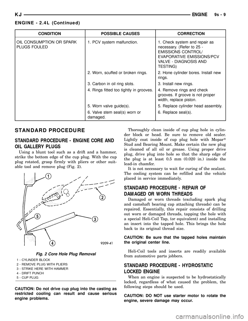
Using a blunt tool such as a drift and a hammer,
strike the bottom edge of the cup plug. With the cup
plug rotated, grasp firmly with pliers or other suit-
able tool and remove plug (Fig. 2).
CAUTION: Do not drive cup plug into the casting as
restricted cooling can result and cause serious
engine problems.Thoroughly clean inside of cup plug hole in cylin-
der block or head. Be sure to remove old sealer.
Lightly coat inside of cup plug hole with Mopart
Stud and Bearing Mount. Make certain the new plug
is cleaned of all oil or grease. Using proper drive
plug, drive plug into hole so that the sharp edge of
the plug is at least 0.5 mm (0.020 in.) inside the
lead-in chamfer.
It is not necessary to wait for curing of the sealant.
The cooling system can be refilled and the vehicle
placed in service immediately.
STANDARD PROCEDURE - REPAIR OF
DAMAGED OR WORN THREADS
Damaged or worn threads (excluding spark plug
and camshaft bearing cap attaching threads) can be
repaired. Essentially, this repair consists of drilling
out worn or damaged threads, tapping the hole with
a special Heli-Coil Tap, (or equivalent) and installing
an insert into the tapped hole. This brings the hole
back to its original thread size.
CAUTION: Be sure that the tapped holes maintain
the original center line.
Heli-Coil tools and inserts are readily available
from automotive parts jobbers.
STANDARD PROCEDURE - HYDROSTATIC
LOCKED ENGINE
When an engine is suspected to be hydrostatically
locked, regardless of what caused the problem, the
following steps should be used.
CAUTION: DO NOT use starter motor to rotate the
engine, severe damage may occur.
Fig. 2 Core Hole Plug Removal
1 - CYLINDER BLOCK
2 - REMOVE PLUG WITH PLIERS
3 - STRIKE HERE WITH HAMMER
4 - DRIFT PUNCH
5 - CUP PLUG
KJENGINE9s-9
ENGINE - 2.4L (Continued)
Page 1328 of 1803

shown in (Fig. 34). Refer to for Engine Specifications
(Refer to 9 - ENGINE - SPECIFICATIONS). Correct
piston to bore clearance must be established in order
to assure quiet and economical operation.
NOTE: Pistons and cylinder bores should be mea-
sured at normal room temperature, 21ÉC (70ÉF).
STANDARD PROCEDURE - CYLINDER BORE
HONING
(1) Used carefully, the cylinder bore resizing hone,
recommended tool C-823 or equivalent, equipped
with 220 grit stones, is the best tool for this honing
procedure. In addition to deglazing, it will reduce
taper and out-of-round as well as removing light
scuffing, scoring or scratches. Usually a few strokes
will clean up a bore and maintain the required lim-
its.
(2) Deglazing of the cylinder walls may be done
using a cylinder surfacing hone, recommended toolC-3501 or equivalent, equipped with 280 grit stones,
if the cylinder bore is straight and round. 20±60
strokes depending on the bore condition, will be suf-
ficient to provide a satisfactory surface. Use a light
honing oil.Do not use engine or transmission oil,
mineral spirits or kerosene.Inspect cylinder walls
after each 20 strokes.
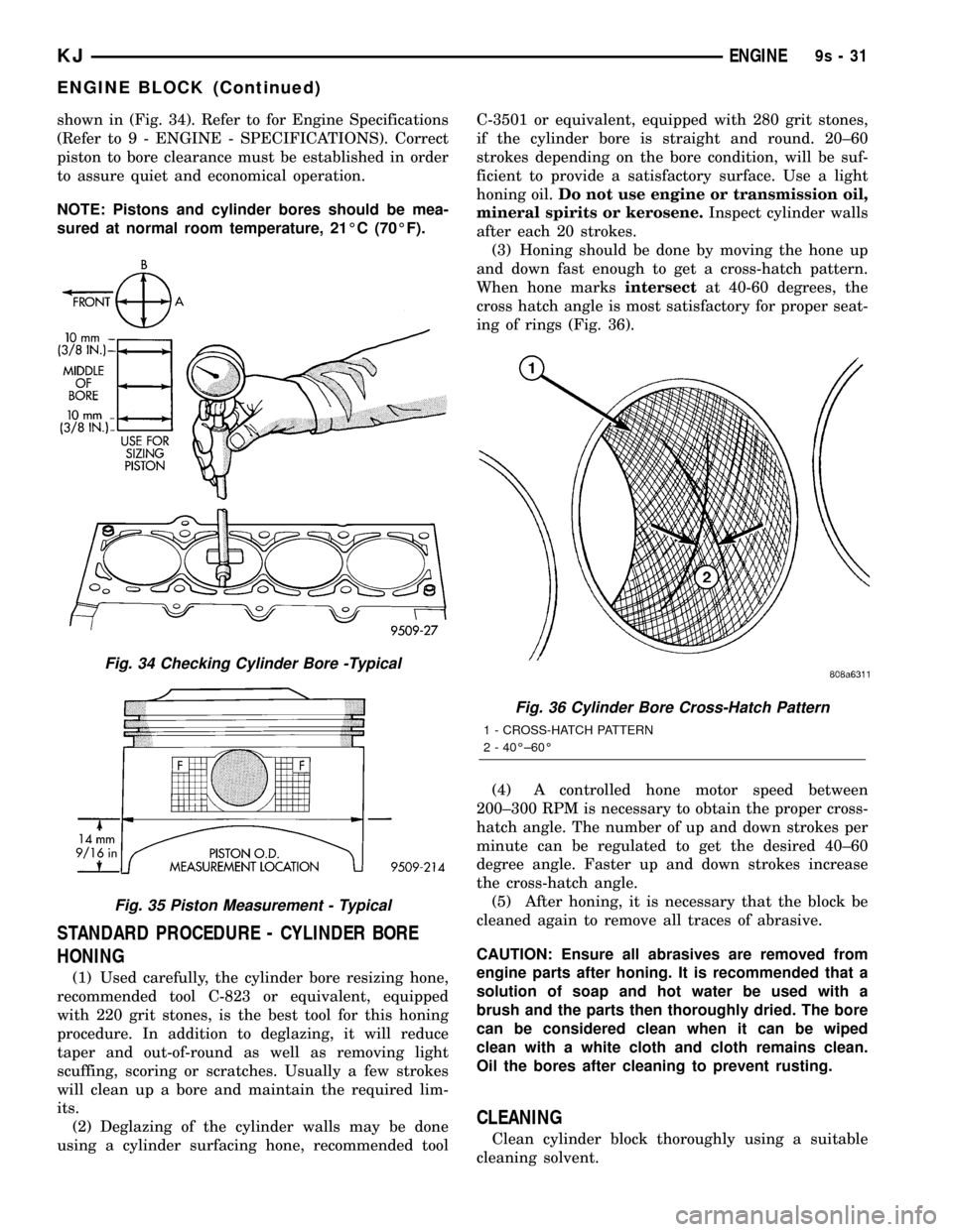
(3) Honing should be done by moving the hone up
and down fast enough to get a cross-hatch pattern.
When hone marksintersectat 40-60 degrees, the
cross hatch angle is most satisfactory for proper seat-
ing of rings (Fig. 36).
(4) A controlled hone motor speed between
200±300 RPM is necessary to obtain the proper cross-
hatch angle. The number of up and down strokes per
minute can be regulated to get the desired 40±60
degree angle. Faster up and down strokes increase
the cross-hatch angle.
(5) After honing, it is necessary that the block be
cleaned again to remove all traces of abrasive.
CAUTION: Ensure all abrasives are removed from
engine parts after honing. It is recommended that a
solution of soap and hot water be used with a
brush and the parts then thoroughly dried. The bore
can be considered clean when it can be wiped
clean with a white cloth and cloth remains clean.
Oil the bores after cleaning to prevent rusting.
CLEANING
Clean cylinder block thoroughly using a suitable
cleaning solvent.
Fig. 34 Checking Cylinder Bore -Typical
Fig. 35 Piston Measurement - Typical
Fig. 36 Cylinder Bore Cross-Hatch Pattern
1 - CROSS-HATCH PATTERN
2 - 40ɱ60É
KJENGINE9s-31
ENGINE BLOCK (Continued)