2002 JEEP LIBERTY fuel filter
[x] Cancel search: fuel filterPage 16 of 1803

centage of antifreeze can cause the engine to over-
heat because specific heat of antifreeze is lower than
that of water.
CAUTION: Richer antifreeze mixtures cannot be
measured with normal field equipment and can
cause problems associated with 100 percent ethyl-
ene-glycol.
CAUTION: Do not use coolant additives that are
claimed to improve engine cooling.
OPERATION - AUTOMATIC TRANSMISSION
FLUID
The automatic transmission fluid is selected based
upon several qualities. The fluid must provide a high
level of protection for the internal components by
providing a lubricating film between adjacent metal
components. The fluid must also be thermally stable
so that it can maintain a consistent viscosity through
a large temperature range. If the viscosity stays con-
stant through the temperature range of operation,
transmission operation and shift feel will remain con-
sistent. Transmission fluid must also be a good con-
ductor of heat. The fluid must absorb heat from the
internal transmission components and transfer that
heat to the transmission case.
FLUID CAPACITIES
SPECIFICATIONS - FLUID CAPACITIES
DESCRIPTION SPECIFICATION
FUEL TANK 18.5 U.S. Gallons (70
Liters)****
ENGINE OIL
Engine Oil - with Filter -
2.4L2.4L (5.0 qts.)
Engine Oil - with Filter -
3.7L3.7L (5.0 qts.)
Engine Oil - With Filter -
2.5L Diesel6.5L (6.9 qts.)
ENGINE COOLANT
Cooling System - 2.4L 9.6L (10.1 qts.)
Cooling System - 3.7L 12.3L (13.0 qts.)
Cooling System - 2.5L
Diesel12.5L (13.2 qts.)
AUTOMATIC TRANSMISSION
Service Fill - 45RFE 4.73L (10.0 pts)
O-haul Fill - 45RFE 13.33L (28.0 pts)
Dry fill capacity Depending on type and size of
internal cooler, length and inside diameter of cooler
lines, or use of an auxiliary cooler, these figures may
vary. (Refer to 21 - TRANSMISSION/TRANSAXLE/
AUTOMATIC/FLUID - STANDARD PROCEDURE)
TRANSFER CASE
NV231 1.4L (2.95 pts.)
NV242 1.6L (3.4 pts.)
MANUAL TRANSMISSION
NV1500 (Approximate dry
fill or fill to bottom edge of
the fill plug hole.)2.28L (2.41 qts.)
NV3550 (Approximate dry
fill or fill to bottom edge of
fill plug hole.)2.28L (2.41 qts.)
FRONT AXLE
186 FIA (Model 30) 1.24L (41.9 fl. oz.)
REAR AXLE
198 RBI (Model 35) 1.78L (60.2 fl. oz.)*
8 1/4 2.08L (4.4 pts.)*
* When equipped with Trac-lok, include 4.0 ounces of
Friction Modifier.
****Nominal refill capacities are shown. A variation
may be observed from vehicle to vehicle due to
manufacturing tolerance and refill procedure.
0 - 4 LUBRICATION & MAINTENANCEKJ
FLUID TYPES (Continued)
Page 286 of 1803

ness routing and retention, connector pin-out infor-
mation and location views for the various wire
harness connectors, splices and grounds.
REMOVAL
(1) Disconnect and isolate the battery negative
cable.
(2) Remove the instrument panel center trim
panel.
(3) Remove the radio mounting screws (Fig. 7).
(4) Disconnect the antenna cable by pulling the
locking antenna connector away from the radio (Fig.
8).
(5) Disconnect the electrical harness connector(s).
(6) Remove radio from instrument panel.
INSTALLATION
(1) Connect the wire harness connector(s).
(2) Connect the antenna cable.
(3) Install the radio to the instrument panel.
(4) Install the radio mounting screws.
(5) Install the instrument panel center trim panel.
(6) Connect the battery negative cable.
RADIO NOISE SUPPRESSION
GROUND STRAP
DESCRIPTION
Radio noise suppression devices are factory-in-
stalled standard equipment on this vehicle. Radio
Frequency Interference (RFI) and ElectroMagnetic
Interference (EMI) can be produced by any on-board
or external source of electromagnetic energy. These
electromagnetic energy sources can radiate electro-
magnetic signals through the air, or conduct them
through the vehicle electrical system.
When the audio system converts RFI or EMI to an
audible acoustic wave form, it is referred to as radio
noise. This undesirable radio noise is generally man-
ifested in the form of ªbuzzing,º ªhissing,º ªpopping,º
ªclicking,º ªcrackling,º and/or ªwhirringº sounds. In
most cases, RFI and EMI radio noise can be sup-
pressed using a combination of vehicle and compo-
nent grounding, filtering and shielding techniques.
This vehicle is equipped with factory-installed radio
noise suppression devices that were designed to min-
imize exposure to typical sources of RFI and EMI;
thereby, minimizing radio noise complaints.
Factory-installed radio noise suppression is accom-
plished primarily through circuitry or devices that
are integral to the factory-installed radios, audio
power amplifiers and other on-board electrical com-
ponents such as generators, wiper motors, blower
motors, and fuel pumps that have been found to be
potential sources of RFI or EMI. External radio noise
suppression devices that are used on this vehicle to
control RFI or EMI, and can be serviced, include the
following:
²Engine-to-body ground strap- This length of
braided ground strap has an eyelet terminal connec-
tor crimped to each end. One end is secured to the
engine cylinder head(s). The other is secured to the
plenum.
²Resistor-type spark plugs- This type of spark
plug has an internal resistor connected in series
between the spark plug terminal and the center elec-
trode to help reduce the production of electromag-
netic radiation that can result in radio noise.
Fig. 7 RADIO
Fig. 8 ANTENNA TO RADIO
1 - RADIO
2 - LOCKING ANTENNA CONNECTOR
3 - INSTRUMENT PANEL ANTENNA CABLE
KJAUDIO 8A - 9
RADIO (Continued)
Page 297 of 1803

tion switch is in any position except On, and elec-
tronic messages are received over the PCI data bus
from the BCM indicating that the exterior lights are
On with the ignition switch in any position except
On, and the status of the driver side front door is not
closed. The BCM uses internal programming and
hard wired inputs from the left (lighting) control
stalk of the multi-function switch, the ignition
switch, and the driver side front door ajar switch to
determine the proper messages to send to the EMIC.
These chimes will continue to sound until the exte-
rior lighting is turned Off, until the ignition switch is
turned to the On position, or until the status of the
driver side front door ajar input changes from not
closed to closed, whichever occurs first.
²Key-In-Ignition Warning- The EMIC chime
tone generator will generate repetitive ªbong-likeº
chime tones at a fast rate when the ignition switch is
in any position except On, and electronic messages
are received over the PCI data bus from the BCM
indicating that the key is in the ignition lock cylinder
with the ignition switch in any position except On,
and the driver side front door is not closed. The BCM
internal programming and hard wired inputs from
the key-in ignition circuitry of the ignition switch,
the ignition switch, and the driver side front door
ajar switch to determine the proper messages to send
to the EMIC. These chimes will continue to sound
until the key is removed from the ignition lock cylin-
der, until the ignition switch is turned to the On
position, or until the status of the driver side front
door ajar input changes from not closed to closed,
whichever occurs first.
²Low Coolant Warning- On vehicles equipped
with a diesel engine, the EMIC chime tone generator
will generate a single ªbong-likeº chime tone when
the ignition switch is first turned to the On position
and a hard wired input from the engine coolant level
sensor to the EMIC indicates that the coolant level is
low for more than about one-quarter second. Any
time after the ignition switch is first turned to the
On position, the EMIC uses internal programming to
check the status of the engine coolant level sensor
inputs about once every second, then adjusts an
internal counter up or down based upon the status of
this input. When the counter accumulates thirty
inputs indicating that the coolant level is low, a sin-
gle chime tone is sounded. This strategy is intended
to reduce the effect that coolant sloshing within the
coolant reservoir can have on reliable chime warning
operation. This warning will only occur once during
an ignition cycle.
²Low Fuel Warning- Each time the ignition
switch is turned to the On position, the EMIC chime
tone generator will generate a single ªbong-likeº
chime tone the first time an electronic message isreceived over the PCI data bus from the PCM
requesting ªLow Fuelº indicator illumination. The
chime will only occur a second time during the same
ignition cycle if another electronic message has been
received from the PCM indicating that there is an
increase in the fuel level equal to about 3 liters (0.8
gallon), then a subsequent electronic message from
the PCM requests ªLow Fuelº indicator illumination.
This strategy combined with filtering performed by
the internal programming of the PCM on the fuel
tank sending unit input is intended to reduce the
possibility of fuel sloshing within the fuel tank caus-
ing multiple low fuel warning chimes during a given
ignition cycle. The EMIC will also respond with the
low fuel warning chime when electronic fuel level
messages are received from the PCM indicating that
the hard wired input to the PCM from the fuel tank
sending unit is an open circuit (greater than full), or
a short circuit (less than empty).
²Low Washer Fluid Warning- The EMIC
chime tone generator will generate a single ªbong-
likeº chime tone when the ignition switch is turned
to the On position and a hard wired input from the
washer fluid level switch to the EMIC indicates the
washer fluid is low for more than about one-quarter
second. Any time after the ignition switch is first
turned to the On position, the EMIC uses internal
programming to check the status of the washer fluid
level switch inputs about once every second, then
adjusts an internal counter up or down based upon
the status of this input. When the counter accumu-
lates thirty inputs indicating that the washer fluid
level is low, a single chime tone is sounded. This
strategy is intended to reduce the effect that fluid
sloshing within the washer reservoir can have on
reliable chime warning operation. This warning will
only occur once during an ignition cycle.
²Overspeed Warning- The EMIC chime tone
generator will generate repetitive ªbong-likeº chime
tones at a slow rate when the ignition switch is in
the On position, and an electronic message received
over the PCI data bus from the PCM indicates that
the vehicle speed is over a programmed speed value.
The PCM uses internal programming and distance
pulse information received over a hard wired vehicle
speed pulse input from the BCM to determine the
proper vehicle speed messages to send to the EMIC.
The BCM uses an internally programmed electronic
pinion factor and a hard wired input from the rear
wheel speed sensor to calculate the proper distance
pulse information to send to the PCM. The electronic
pinion factor represents the proper tire size and axle
ratio information for the vehicle. These chimes will
continue to sound until the vehicle speed messages
are below the programmed speed value, or until the
ignition switch is turned to the Off position, which-
8B - 4 CHIME/BUZZERKJ
CHIME WARNING SYSTEM (Continued)
Page 1219 of 1803

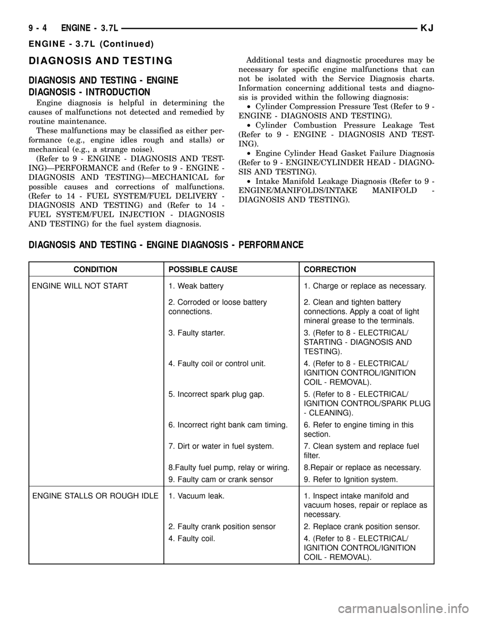
DIAGNOSIS AND TESTING
DIAGNOSIS AND TESTING - ENGINE
DIAGNOSIS - INTRODUCTION
Engine diagnosis is helpful in determining the
causes of malfunctions not detected and remedied by
routine maintenance.
These malfunctions may be classified as either per-
formance (e.g., engine idles rough and stalls) or
mechanical (e.g., a strange noise).
(Refer to 9 - ENGINE - DIAGNOSIS AND TEST-
ING)ÐPERFORMANCE and (Refer to 9 - ENGINE -
DIAGNOSIS AND TESTING)ÐMECHANICAL for
possible causes and corrections of malfunctions.
(Refer to 14 - FUEL SYSTEM/FUEL DELIVERY -
DIAGNOSIS AND TESTING) and (Refer to 14 -
FUEL SYSTEM/FUEL INJECTION - DIAGNOSIS
AND TESTING) for the fuel system diagnosis.Additional tests and diagnostic procedures may be
necessary for specific engine malfunctions that can
not be isolated with the Service Diagnosis charts.
Information concerning additional tests and diagno-
sis is provided within the following diagnosis:
²Cylinder Compression Pressure Test (Refer to 9 -
ENGINE - DIAGNOSIS AND TESTING).
²Cylinder Combustion Pressure Leakage Test
(Refer to 9 - ENGINE - DIAGNOSIS AND TEST-
ING).
²Engine Cylinder Head Gasket Failure Diagnosis
(Refer to 9 - ENGINE/CYLINDER HEAD - DIAGNO-
SIS AND TESTING).
²Intake Manifold Leakage Diagnosis (Refer to 9 -
ENGINE/MANIFOLDS/INTAKE MANIFOLD -
DIAGNOSIS AND TESTING).
DIAGNOSIS AND TESTING - ENGINE DIAGNOSIS - PERFORMANCE
CONDITION POSSIBLE CAUSE CORRECTION
ENGINE WILL NOT START 1. Weak battery 1. Charge or replace as necessary.
2. Corroded or loose battery
connections.2. Clean and tighten battery
connections. Apply a coat of light
mineral grease to the terminals.
3. Faulty starter. 3. (Refer to 8 - ELECTRICAL/
STARTING - DIAGNOSIS AND
TESTING).
4. Faulty coil or control unit. 4. (Refer to 8 - ELECTRICAL/
IGNITION CONTROL/IGNITION
COIL - REMOVAL).
5. Incorrect spark plug gap. 5. (Refer to 8 - ELECTRICAL/
IGNITION CONTROL/SPARK PLUG
- CLEANING).
6. Incorrect right bank cam timing. 6. Refer to engine timing in this
section.
7. Dirt or water in fuel system. 7. Clean system and replace fuel
filter.
8.Faulty fuel pump, relay or wiring. 8.Repair or replace as necessary.
9. Faulty cam or crank sensor 9. Refer to Ignition system.
ENGINE STALLS OR ROUGH IDLE 1. Vacuum leak. 1. Inspect intake manifold and
vacuum hoses, repair or replace as
necessary.
2. Faulty crank position sensor 2. Replace crank position sensor.
4. Faulty coil. 4. (Refer to 8 - ELECTRICAL/
IGNITION CONTROL/IGNITION
COIL - REMOVAL).
9 - 4 ENGINE - 3.7LKJ
ENGINE - 3.7L (Continued)
Page 1220 of 1803

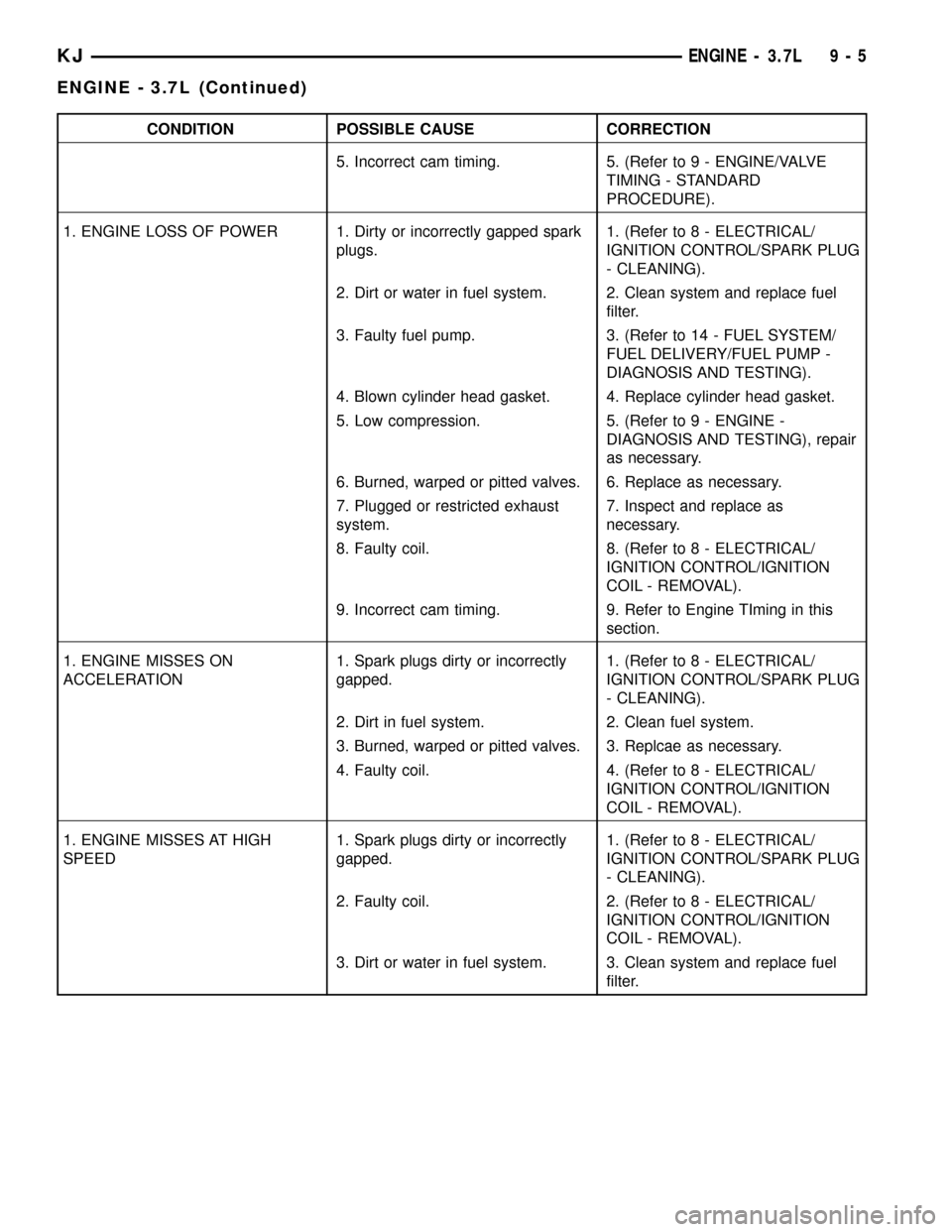
CONDITION POSSIBLE CAUSE CORRECTION
5. Incorrect cam timing. 5. (Refer to 9 - ENGINE/VALVE
TIMING - STANDARD
PROCEDURE).
1. ENGINE LOSS OF POWER 1. Dirty or incorrectly gapped spark
plugs.1. (Refer to 8 - ELECTRICAL/
IGNITION CONTROL/SPARK PLUG
- CLEANING).
2. Dirt or water in fuel system. 2. Clean system and replace fuel
filter.
3. Faulty fuel pump. 3. (Refer to 14 - FUEL SYSTEM/
FUEL DELIVERY/FUEL PUMP -
DIAGNOSIS AND TESTING).
4. Blown cylinder head gasket. 4. Replace cylinder head gasket.
5. Low compression. 5. (Refer to 9 - ENGINE -
DIAGNOSIS AND TESTING), repair
as necessary.
6. Burned, warped or pitted valves. 6. Replace as necessary.
7. Plugged or restricted exhaust
system.7. Inspect and replace as
necessary.
8. Faulty coil. 8. (Refer to 8 - ELECTRICAL/
IGNITION CONTROL/IGNITION
COIL - REMOVAL).
9. Incorrect cam timing. 9. Refer to Engine TIming in this
section.
1. ENGINE MISSES ON
ACCELERATION1. Spark plugs dirty or incorrectly
gapped.1. (Refer to 8 - ELECTRICAL/
IGNITION CONTROL/SPARK PLUG
- CLEANING).
2. Dirt in fuel system. 2. Clean fuel system.
3. Burned, warped or pitted valves. 3. Replcae as necessary.
4. Faulty coil. 4. (Refer to 8 - ELECTRICAL/
IGNITION CONTROL/IGNITION
COIL - REMOVAL).
1. ENGINE MISSES AT HIGH
SPEED1. Spark plugs dirty or incorrectly
gapped.1. (Refer to 8 - ELECTRICAL/
IGNITION CONTROL/SPARK PLUG
- CLEANING).
2. Faulty coil. 2. (Refer to 8 - ELECTRICAL/
IGNITION CONTROL/IGNITION
COIL - REMOVAL).
3. Dirt or water in fuel system. 3. Clean system and replace fuel
filter.
KJENGINE - 3.7L 9 - 5
ENGINE - 3.7L (Continued)
Page 1276 of 1803

DIAGNOSIS AND TESTING - REAR SEAL AREA
LEAKS
Since it is sometimes difficult to determine the
source of an oil leak in the rear seal area of the
engine, a more involved inspection is necessary. The
following steps should be followed to help pinpoint
the source of the leak.
If the leakage occurs at the crankshaft rear oil seal
area:
(1) Disconnect the battery.
(2) Raise the vehicle.
(3) Remove torque converter or clutch housing
cover and inspect rear of block for evidence of oil.
Use a black light to check for the oil leak:
(a) Circular spray pattern generally indicates
seal leakage or crankshaft damage.
(b) Where leakage tends to run straight down,
possible causes are a porous block, camshaft bore
cup plugs, oil galley pipe plugs, oil filter runoff,
and main bearing cap to cylinder block mating sur-
faces. See Engine, for proper repair procedures of
these items.
(4) If no leaks are detected, pressurized the crank-
case as outlined in the section, Inspection (Engine oil
Leaks in general)
CAUTION: Do not exceed 20.6 kPa (3 psi).(5) If the leak is not detected, very slowly turn the
crankshaft and watch for leakage. If a leak is
detected between the crankshaft and seal while
slowly turning the crankshaft, it is possible the
crankshaft seal surface is damaged. The seal area on
the crankshaft could have minor nicks or scratches
that can be polished out with emery cloth.
CAUTION: Use extreme caution when crankshaft
polishing is necessary to remove minor nicks or
scratches. The crankshaft seal flange is specially
machined to complement the function of the rear oil
seal.
(6) For bubbles that remain steady with shaft
rotation, no further inspection can be done until dis-
assembled. (Refer to 9 - ENGINE - DIAGNOSIS AND
TESTING), under the Oil Leak row, for components
inspections on possible causes and corrections.
(7) After the oil leak root cause and appropriate
corrective action have been identified, (Refer to 9 -
ENGINE/ENGINE BLOCK/CRANKSHAFT OIL
SEAL - REAR - REMOVAL).
OIL
STANDARD PROCEDURE - ENGINE OIL
WARNING: NEW OR USED ENGINE OIL CAN BE
IRRITATING TO THE SKIN. AVOID PROLONGED OR
REPEATED SKIN CONTACT WITH ENGINE OIL.
CONTAMINANTS IN USED ENGINE OIL, CAUSED BY
INTERNAL COMBUSTION, CAN BE HAZARDOUS TO
YOUR HEALTH. THOROUGHLY WASH EXPOSED
SKIN WITH SOAP AND WATER. DO NOT WASH
SKIN WITH GASOLINE, DIESEL FUEL, THINNER, OR
SOLVENTS, HEALTH PROBLEMS CAN RESULT. DO
NOT POLLUTE, DISPOSE OF USED ENGINE OIL
PROPERLY.
ENGINE OIL SPECIFICATION
CAUTION: Do not use non-detergent or straight
mineral oil when adding or changing crankcase
lubricant. Engine failure can result.
API SERVICE GRADE CERTIFIED
Use an engine oil that is API Service Grade Certi-
fied. MOPARtprovides engine oils that conform to
this service grade.
SAE VISCOSITY
An SAE viscosity grade is used to specify the vis-
cosity of engine oil. Use only engine oils with multi-
Fig. 70 Oil Pressure Sending Unit -Typical
1 - BELT
2 - OIL PRESSURE SENSOR
3 - OIL FILTER
4 - ELEC. CONNECTOR
KJENGINE - 3.7L 9 - 61
LUBRICATION (Continued)
Page 1302 of 1803

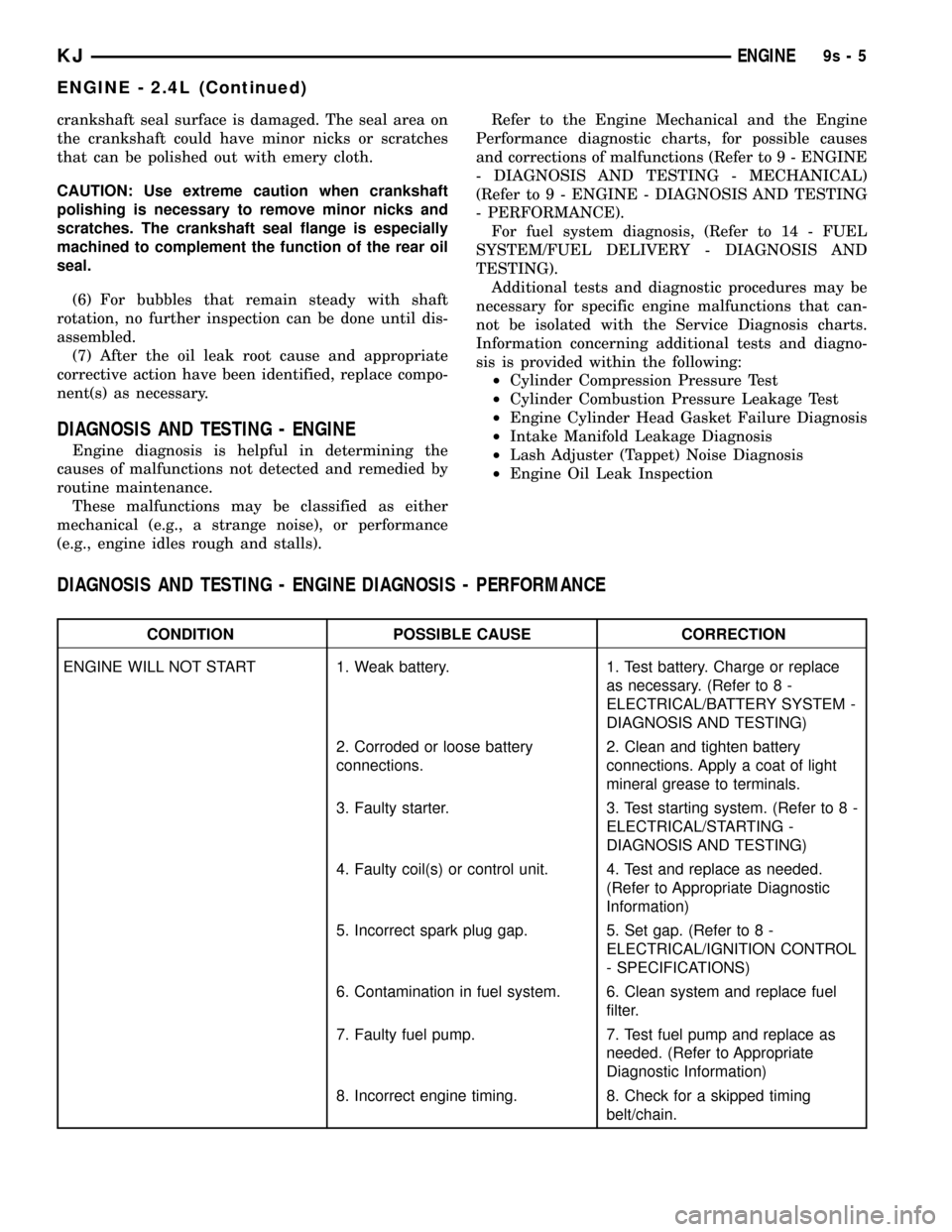
crankshaft seal surface is damaged. The seal area on
the crankshaft could have minor nicks or scratches
that can be polished out with emery cloth.
CAUTION: Use extreme caution when crankshaft
polishing is necessary to remove minor nicks and
scratches. The crankshaft seal flange is especially
machined to complement the function of the rear oil
seal.
(6) For bubbles that remain steady with shaft
rotation, no further inspection can be done until dis-
assembled.
(7) After the oil leak root cause and appropriate
corrective action have been identified, replace compo-
nent(s) as necessary.
DIAGNOSIS AND TESTING - ENGINE
Engine diagnosis is helpful in determining the
causes of malfunctions not detected and remedied by
routine maintenance.
These malfunctions may be classified as either
mechanical (e.g., a strange noise), or performance
(e.g., engine idles rough and stalls).Refer to the Engine Mechanical and the Engine
Performance diagnostic charts, for possible causes
and corrections of malfunctions (Refer to 9 - ENGINE
- DIAGNOSIS AND TESTING - MECHANICAL)
(Refer to 9 - ENGINE - DIAGNOSIS AND TESTING
- PERFORMANCE).
For fuel system diagnosis, (Refer to 14 - FUEL
SYSTEM/FUEL DELIVERY - DIAGNOSIS AND
TESTING).
Additional tests and diagnostic procedures may be
necessary for specific engine malfunctions that can-
not be isolated with the Service Diagnosis charts.
Information concerning additional tests and diagno-
sis is provided within the following:
²Cylinder Compression Pressure Test
²Cylinder Combustion Pressure Leakage Test
²Engine Cylinder Head Gasket Failure Diagnosis
²Intake Manifold Leakage Diagnosis
²Lash Adjuster (Tappet) Noise Diagnosis
²Engine Oil Leak Inspection
DIAGNOSIS AND TESTING - ENGINE DIAGNOSIS - PERFORMANCE
CONDITION POSSIBLE CAUSE CORRECTION
ENGINE WILL NOT START 1. Weak battery. 1. Test battery. Charge or replace
as necessary. (Refer to 8 -
ELECTRICAL/BATTERY SYSTEM -
DIAGNOSIS AND TESTING)
2. Corroded or loose battery
connections.2. Clean and tighten battery
connections. Apply a coat of light
mineral grease to terminals.
3. Faulty starter. 3. Test starting system. (Refer to 8 -
ELECTRICAL/STARTING -
DIAGNOSIS AND TESTING)
4. Faulty coil(s) or control unit. 4. Test and replace as needed.
(Refer to Appropriate Diagnostic
Information)
5. Incorrect spark plug gap. 5. Set gap. (Refer to 8 -
ELECTRICAL/IGNITION CONTROL
- SPECIFICATIONS)
6. Contamination in fuel system. 6. Clean system and replace fuel
filter.
7. Faulty fuel pump. 7. Test fuel pump and replace as
needed. (Refer to Appropriate
Diagnostic Information)
8. Incorrect engine timing. 8. Check for a skipped timing
belt/chain.
KJENGINE9s-5
ENGINE - 2.4L (Continued)
Page 1303 of 1803

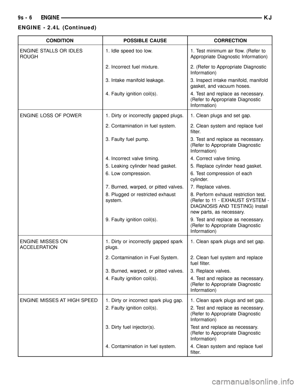
CONDITION POSSIBLE CAUSE CORRECTION
ENGINE STALLS OR IDLES
ROUGH1. Idle speed too low. 1. Test minimum air flow. (Refer to
Appropriate Diagnostic Information)
2. Incorrect fuel mixture. 2. (Refer to Appropriate Diagnostic
Information)
3. Intake manifold leakage. 3. Inspect intake manifold, manifold
gasket, and vacuum hoses.
4. Faulty ignition coil(s). 4. Test and replace as necessary.
(Refer to Appropriate Diagnostic
Information)
ENGINE LOSS OF POWER 1. Dirty or incorrectly gapped plugs. 1. Clean plugs and set gap.
2. Contamination in fuel system. 2. Clean system and replace fuel
filter.
3. Faulty fuel pump. 3. Test and replace as necessary.
(Refer to Appropriate Diagnostic
Information)
4. Incorrect valve timing. 4. Correct valve timing.
5. Leaking cylinder head gasket. 5. Replace cylinder head gasket.
6. Low compression. 6. Test compression of each
cylinder.
7. Burned, warped, or pitted valves. 7. Replace valves.
8. Plugged or restricted exhaust
system.8. Perform exhaust restriction test.
(Refer to 11 - EXHAUST SYSTEM -
DIAGNOSIS AND TESTING) Install
new parts, as necessary.
9. Faulty ignition coil(s). 9. Test and replace as necessary.
(Refer to Appropriate Diagnostic
Information)
ENGINE MISSES ON
ACCELERATION1. Dirty or incorrectly gapped spark
plugs.1. Clean spark plugs and set gap.
2. Contamination in Fuel System. 2. Clean fuel system and replace
fuel filter.
3. Burned, warped, or pitted valves. 3. Replace valves.
4. Faulty ignition coil(s). 4. Test and replace as necessary.
(Refer to Appropriate Diagnostic
Information)
ENGINE MISSES AT HIGH SPEED 1. Dirty or incorrect spark plug gap. 1. Clean spark plugs and set gap.
2. Faulty ignition coil(s). 2. Test and replace as necessary.
(Refer to Appropriate Diagnostic
Information)
3. Dirty fuel injector(s). Test and replace as necessary.
(Refer to Appropriate Diagnostic
Information)
4. Contamination in fuel system. 4. Clean system and replace fuel
filter.
9s - 6 ENGINEKJ
ENGINE - 2.4L (Continued)