2002 JEEP LIBERTY fuel filter
[x] Cancel search: fuel filterPage 1408 of 1803
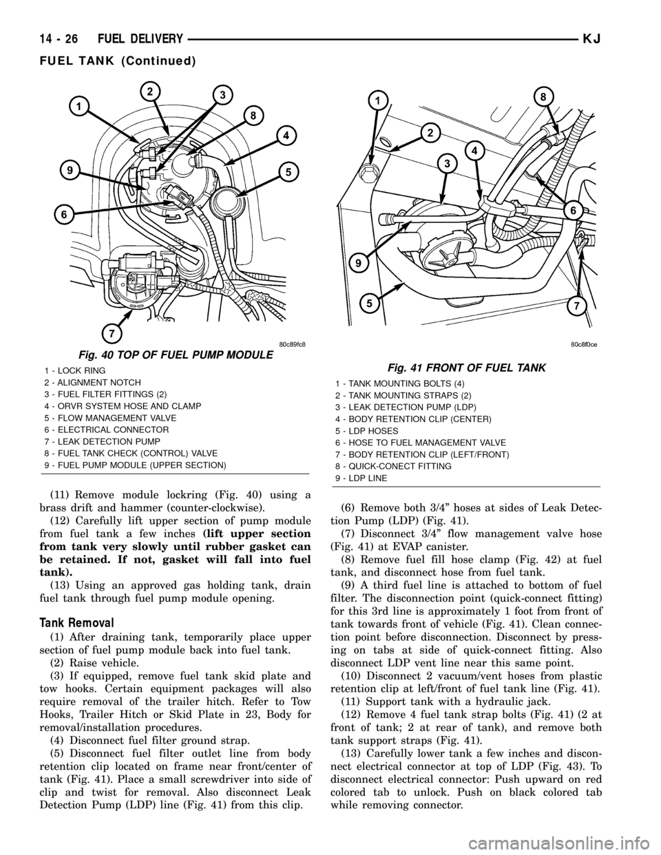
(11) Remove module lockring (Fig. 40) using a
brass drift and hammer (counter-clockwise).
(12) Carefully lift upper section of pump module
from fuel tank a few inches(lift upper section
from tank very slowly until rubber gasket can
be retained. If not, gasket will fall into fuel
tank).
(13) Using an approved gas holding tank, drain
fuel tank through fuel pump module opening.
Tank Removal
(1) After draining tank, temporarily place upper
section of fuel pump module back into fuel tank.
(2) Raise vehicle.
(3) If equipped, remove fuel tank skid plate and
tow hooks. Certain equipment packages will also
require removal of the trailer hitch. Refer to Tow
Hooks, Trailer Hitch or Skid Plate in 23, Body for
removal/installation procedures.
(4) Disconnect fuel filter ground strap.
(5) Disconnect fuel filter outlet line from body
retention clip located on frame near front/center of
tank (Fig. 41). Place a small screwdriver into side of
clip and twist for removal. Also disconnect Leak
Detection Pump (LDP) line (Fig. 41) from this clip.(6) Remove both 3/4º hoses at sides of Leak Detec-
tion Pump (LDP) (Fig. 41).
(7) Disconnect 3/4º flow management valve hose
(Fig. 41) at EVAP canister.
(8) Remove fuel fill hose clamp (Fig. 42) at fuel
tank, and disconnect hose from fuel tank.
(9) A third fuel line is attached to bottom of fuel
filter. The disconnection point (quick-connect fitting)
for this 3rd line is approximately 1 foot from front of
tank towards front of vehicle (Fig. 41). Clean connec-
tion point before disconnection. Disconnect by press-
ing on tabs at side of quick-connect fitting. Also
disconnect LDP vent line near this same point.
(10) Disconnect 2 vacuum/vent hoses from plastic
retention clip at left/front of fuel tank line (Fig. 41).
(11) Support tank with a hydraulic jack.
(12) Remove 4 fuel tank strap bolts (Fig. 41) (2 at
front of tank; 2 at rear of tank), and remove both
tank support straps (Fig. 41).
(13) Carefully lower tank a few inches and discon-
nect electrical connector at top of LDP (Fig. 43). To
disconnect electrical connector: Push upward on red
colored tab to unlock. Push on black colored tab
while removing connector.
Fig. 40 TOP OF FUEL PUMP MODULE
1 - LOCK RING
2 - ALIGNMENT NOTCH
3 - FUEL FILTER FITTINGS (2)
4 - ORVR SYSTEM HOSE AND CLAMP
5 - FLOW MANAGEMENT VALVE
6 - ELECTRICAL CONNECTOR
7 - LEAK DETECTION PUMP
8 - FUEL TANK CHECK (CONTROL) VALVE
9 - FUEL PUMP MODULE (UPPER SECTION)Fig. 41 FRONT OF FUEL TANK
1 - TANK MOUNTING BOLTS (4)
2 - TANK MOUNTING STRAPS (2)
3 - LEAK DETECTION PUMP (LDP)
4 - BODY RETENTION CLIP (CENTER)
5 - LDP HOSES
6 - HOSE TO FUEL MANAGEMENT VALVE
7 - BODY RETENTION CLIP (LEFT/FRONT)
8 - QUICK-CONECT FITTING
9 - LDP LINE
14 - 26 FUEL DELIVERYKJ
FUEL TANK (Continued)
Page 1409 of 1803
(14) Continue lowering tank while guiding remain-
ing hoses and lines.
(15) If fuel tank is to be replaced, remove LDP,
fuel filter and fuel pump module from tank. Refer to
Leak Detection Pump, Fuel Filter and Fuel Pump
Module Removal/Installation procedures.
INSTALLATION
(1) If fuel tank is to be replaced, install LDP, fuel
filter and fuel pump module to tank. Refer to Leak
Detection Pump, Fuel Filter and Fuel Pump Module
Removal/Installation procedures.
(2) Position fuel tank to hydraulic jack.
(3) Raise tank while carefully guiding vent tubes/
hoses through frame rail and crossmember. Before
tank reaches body, connect electrical connector to
Leak Detection Pump (LDP).
(4) Continue raising tank until positioned to body.
(5) Attach two fuel tank mounting straps and 4
mounting bolts. Tighten bolts to 61 N´m (45 ft. lbs.)
torque.
(6) Connect 2 hoses to body retention clip at left/
front of tank.
(7) Connect fuel filter fuel line to main fuel line
(snaps together). After connecting, snap this line into
body retention clip. Also connect LDP vacuum hose
near this point.(8) Install fuel fill hose and hose clamp to fuel
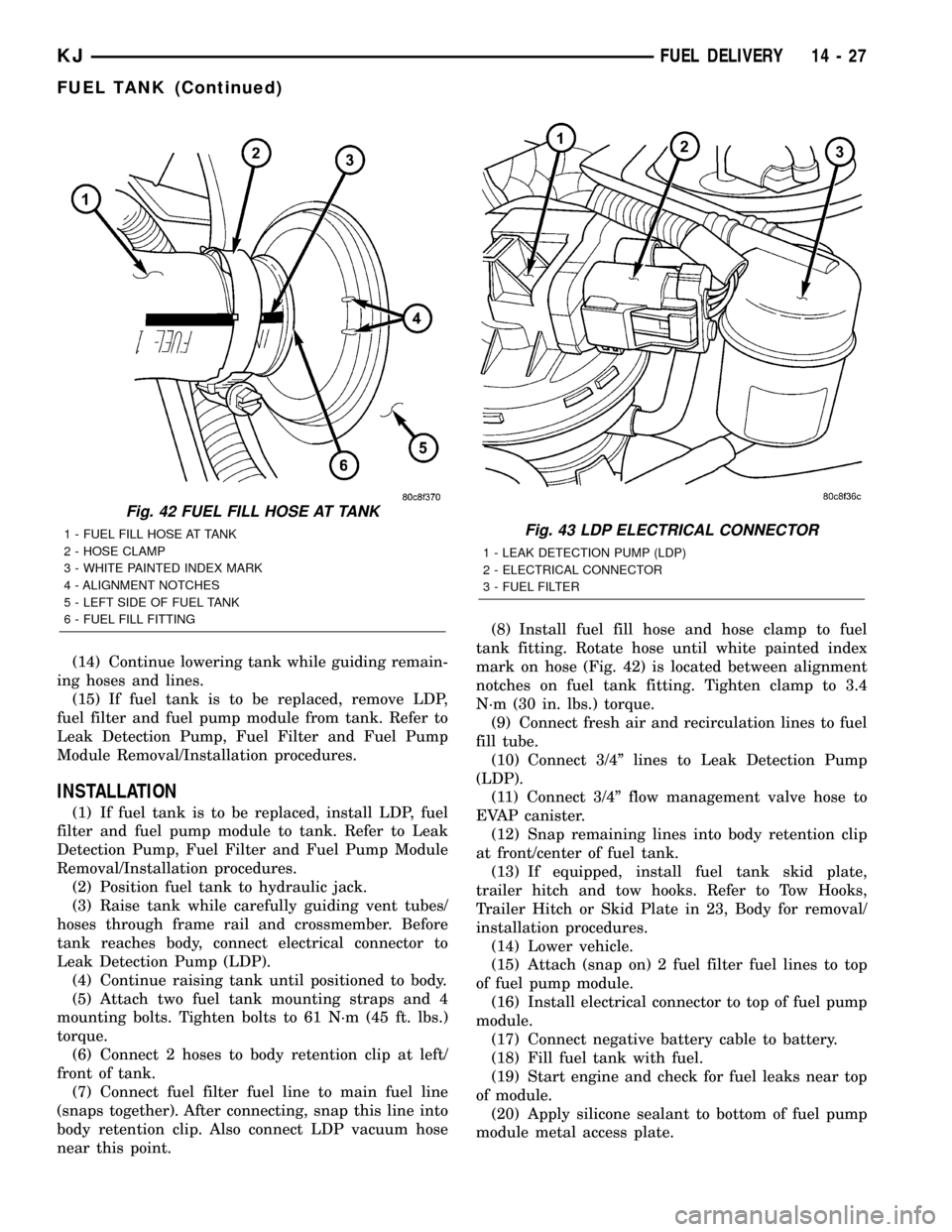
tank fitting. Rotate hose until white painted index
mark on hose (Fig. 42) is located between alignment
notches on fuel tank fitting. Tighten clamp to 3.4
N´m (30 in. lbs.) torque.
(9) Connect fresh air and recirculation lines to fuel
fill tube.
(10) Connect 3/4º lines to Leak Detection Pump
(LDP).
(11) Connect 3/4º flow management valve hose to
EVAP canister.
(12) Snap remaining lines into body retention clip
at front/center of fuel tank.
(13) If equipped, install fuel tank skid plate,
trailer hitch and tow hooks. Refer to Tow Hooks,
Trailer Hitch or Skid Plate in 23, Body for removal/
installation procedures.
(14) Lower vehicle.
(15) Attach (snap on) 2 fuel filter fuel lines to top
of fuel pump module.
(16) Install electrical connector to top of fuel pump
module.
(17) Connect negative battery cable to battery.
(18) Fill fuel tank with fuel.
(19) Start engine and check for fuel leaks near top
of module.
(20) Apply silicone sealant to bottom of fuel pump
module metal access plate.
Fig. 42 FUEL FILL HOSE AT TANK
1 - FUEL FILL HOSE AT TANK
2 - HOSE CLAMP
3 - WHITE PAINTED INDEX MARK
4 - ALIGNMENT NOTCHES
5 - LEFT SIDE OF FUEL TANK
6 - FUEL FILL FITTINGFig. 43 LDP ELECTRICAL CONNECTOR
1 - LEAK DETECTION PUMP (LDP)
2 - ELECTRICAL CONNECTOR
3 - FUEL FILTER
KJFUEL DELIVERY 14 - 27
FUEL TANK (Continued)
Page 1410 of 1803
(21) Install fuel pump module metal access plate
and 4 nuts. Tighten nuts to 3 N´m (26 in. lbs.)
torque.
(22) Position carpet and install 2 new cargo clamp
rivets into each cargo holdown clamp.
FUEL TANK CHECK VALVE
DESCRIPTION
The fuel tank is equipped with a check valve. The
valve (also referred to as a control valve) is located in
the top section of the fuel pump module assembly
(Fig. 1).
OPERATION
The fuel tank check valve (also referred to as
either a control valve, one-way check valve or float
valve) will prevent fuel flow through the fuel tank
vent in the event of an accidental vehicle rollover. It
is also used as a part of the ORVR system. The
EVAP canister and ORVR system draw fuel vapors
from the fuel tank through this valve. Refer to ORVR
in Emissions for additional information.
The valve may be serviced by replacing the upper
section of the fuel pump module assembly.
REMOVAL
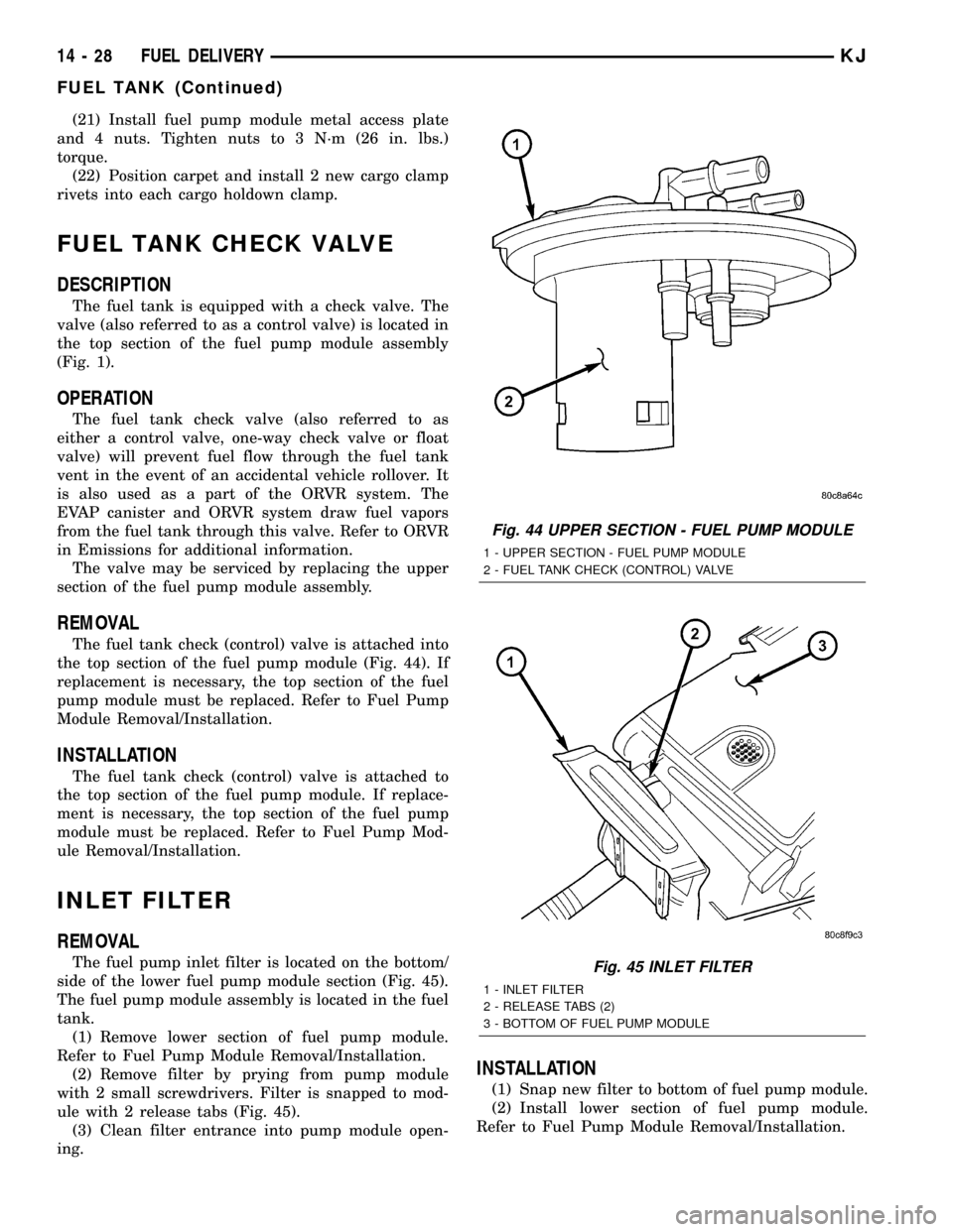
The fuel tank check (control) valve is attached into
the top section of the fuel pump module (Fig. 44). If
replacement is necessary, the top section of the fuel
pump module must be replaced. Refer to Fuel Pump
Module Removal/Installation.
INSTALLATION
The fuel tank check (control) valve is attached to
the top section of the fuel pump module. If replace-
ment is necessary, the top section of the fuel pump
module must be replaced. Refer to Fuel Pump Mod-
ule Removal/Installation.
INLET FILTER
REMOVAL
The fuel pump inlet filter is located on the bottom/
side of the lower fuel pump module section (Fig. 45).
The fuel pump module assembly is located in the fuel
tank.
(1) Remove lower section of fuel pump module.
Refer to Fuel Pump Module Removal/Installation.
(2) Remove filter by prying from pump module
with 2 small screwdrivers. Filter is snapped to mod-
ule with 2 release tabs (Fig. 45).
(3) Clean filter entrance into pump module open-
ing.
INSTALLATION
(1) Snap new filter to bottom of fuel pump module.
(2) Install lower section of fuel pump module.
Refer to Fuel Pump Module Removal/Installation.
Fig. 44 UPPER SECTION - FUEL PUMP MODULE
1 - UPPER SECTION - FUEL PUMP MODULE
2 - FUEL TANK CHECK (CONTROL) VALVE
Fig. 45 INLET FILTER
1 - INLET FILTER
2 - RELEASE TABS (2)
3 - BOTTOM OF FUEL PUMP MODULE
14 - 28 FUEL DELIVERYKJ
FUEL TANK (Continued)
Page 1425 of 1803
WARNING: THE EXHAUST MANIFOLD, EXHAUST
PIPES AND CATALYTIC CONVERTER BECOME
VERY HOT DURING ENGINE OPERATION. ALLOW
ENGINE TO COOL BEFORE REMOVING OXYGEN
SENSOR.
(1) Raise and support vehicle.
(2) Disconnect wire connector from O2S sensor.
CAUTION: When disconnecting sensor electrical
connector, do not pull directly on wire going into
sensor.
(3) Remove O2S sensor with an oxygen sensor
removal and installation tool.
(4) Clean threads in exhaust pipe using appropri-
ate tap.
INSTALLATION
Threads of new oxygen sensors are factory coated
with anti-seize compound to aid in removal.DO
NOT add any additional anti-seize compound to
threads of a new oxygen sensor.
(1) Install O2S sensor. Tighten to 30 N´m (22 ft.
lbs.) torque.
(2) Connect O2S sensor wire connector.
(3) Lower vehicle.
THROTTLE BODY
DESCRIPTION
The throttle body is located on the intake manifold.
Fuel does not enter the intake manifold through the
throttle body. Fuel is sprayed into the manifold by
the fuel injectors.
OPERATION
Filtered air from the air cleaner enters the intake
manifold through the throttle body. The throttle body
contains an air control passage controlled by an Idle
Air Control (IAC) motor. The air control passage is
used to supply air for idle conditions. A throttle valve
(plate) is used to supply air for above idle conditions.
Certain sensors are attached to the throttle body.
The accelerator pedal cable, speed control cable and
transmission control cable (when equipped) are con-
nected to the throttle body linkage arm.
A (factory adjusted) set screw is used to mechani-
cally limit the position of the throttle body throttle
plate.Never attempt to adjust the engine idle
speed using this screw.All idle speed functions are
controlled by the PCM.
REMOVAL
2.4L
A (factory adjusted) set screw is used to mechani-
cally limit the position of the throttle body throttle
plate.Never attempt to adjust the engine idle
speed using this screw.All idle speed functions are
controlled by the Powertrain Control Module (PCM).
(1) Remove air cleaner tube at throttle body.
(2) Disconnect throttle body electrical connectors
at IAC motor and TPS.
(3) Remove all control cables from throttle body
(lever) arm. Refer to the Accelerator Pedal and Throt-
tle Cable section for removal/installation procedures.
(4) Disconnect necessary vacuum lines at throttle
body.
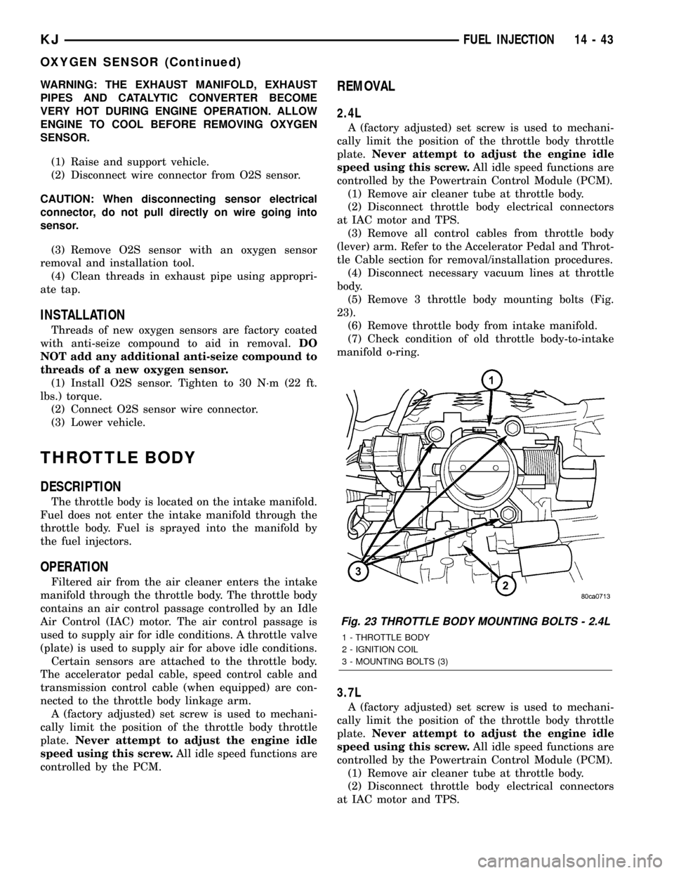
(5) Remove 3 throttle body mounting bolts (Fig.
23).
(6) Remove throttle body from intake manifold.
(7) Check condition of old throttle body-to-intake
manifold o-ring.
3.7L
A (factory adjusted) set screw is used to mechani-
cally limit the position of the throttle body throttle
plate.Never attempt to adjust the engine idle
speed using this screw.All idle speed functions are
controlled by the Powertrain Control Module (PCM).
(1) Remove air cleaner tube at throttle body.
(2) Disconnect throttle body electrical connectors
at IAC motor and TPS.
Fig. 23 THROTTLE BODY MOUNTING BOLTS - 2.4L
1 - THROTTLE BODY
2 - IGNITION COIL
3 - MOUNTING BOLTS (3)
KJFUEL INJECTION 14 - 43
OXYGEN SENSOR (Continued)
Page 1726 of 1803
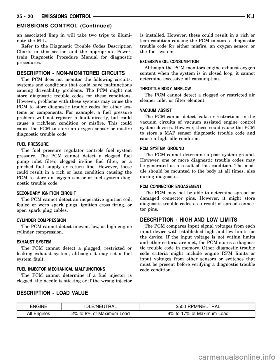
an associated limp in will take two trips to illumi-
nate the MIL.
Refer to the Diagnostic Trouble Codes Description
Charts in this section and the appropriate Power-
train Diagnostic Procedure Manual for diagnostic
procedures.
DESCRIPTION - NON-MONITORED CIRCUITS
The PCM does not monitor the following circuits,
systems and conditions that could have malfunctions
causing driveability problems. The PCM might not
store diagnostic trouble codes for these conditions.
However, problems with these systems may cause the
PCM to store diagnostic trouble codes for other sys-
tems or components. For example, a fuel pressure
problem will not register a fault directly, but could
cause a rich/lean condition or misfire. This could
cause the PCM to store an oxygen sensor or misfire
diagnostic trouble code
FUEL PRESSURE
The fuel pressure regulator controls fuel system
pressure. The PCM cannot detect a clogged fuel
pump inlet filter, clogged in-line fuel filter, or a
pinched fuel supply or return line. However, these
could result in a rich or lean condition causing the
PCM to store an oxygen sensor or fuel system diag-
nostic trouble code.
SECONDARY IGNITION CIRCUIT
The PCM cannot detect an inoperative ignition coil,
fouled or worn spark plugs, ignition cross firing, or
open spark plug cables.
CYLINDER COMPRESSION
The PCM cannot detect uneven, low, or high engine
cylinder compression.
EXHAUST SYSTEM
The PCM cannot detect a plugged, restricted or
leaking exhaust system, although it may set a fuel
system fault.
FUEL INJECTOR MECHANICAL MALFUNCTIONS
The PCM cannot determine if a fuel injector is
clogged, the needle is sticking or if the wrong injectoris installed. However, these could result in a rich or
lean condition causing the PCM to store a diagnostic
trouble code for either misfire, an oxygen sensor, or
the fuel system.
EXCESSIVE OIL CONSUMPTION
Although the PCM monitors engine exhaust oxygen
content when the system is in closed loop, it cannot
determine excessive oil consumption.
THROTTLE BODY AIRFLOW
The PCM cannot detect a clogged or restricted air
cleaner inlet or filter element.
VACUUM ASSIST
The PCM cannot detect leaks or restrictions in the
vacuum circuits of vacuum assisted engine control
system devices. However, these could cause the PCM
to store a MAP sensor diagnostic trouble code and
cause a high idle condition.
PCM SYSTEM GROUND
The PCM cannot determine a poor system ground.
However, one or more diagnostic trouble codes may
be generated as a result of this condition. The mod-
ule should be mounted to the body at all times, also
during diagnostic.
PCM CONNECTOR ENGAGEMENT
The PCM may not be able to determine spread or
damaged connector pins. However, it might store
diagnostic trouble codes as a result of spread connec-
tor pins.
DESCRIPTION - HIGH AND LOW LIMITS
The PCM compares input signal voltages from each
input device with established high and low limits for
the device. If the input voltage is not within limits
and other criteria are met, the PCM stores a diagnos-
tic trouble code in memory. Other diagnostic trouble
code criteria might include engine RPM limits or
input voltages from other sensors or switches that
must be present before verifying a diagnostic trouble
code condition.
DESCRIPTION - LOAD VALUE
ENGINE IDLE/NEUTRAL 2500 RPM/NEUTRAL
All Engines 2% to 8% of Maximum Load 9% to 17% of Maximum Load
25 - 20 EMISSIONS CONTROLKJ
EMISSIONS CONTROL (Continued)
Page 1731 of 1803
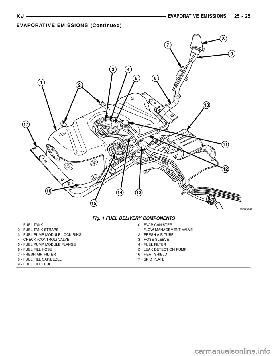
Fig. 1 FUEL DELIVERY COMPONENTS
1 - FUEL TANK 10 - EVAP CANISTER
2 - FUEL TANK STRAPS 11 - FLOW MANAGEMENT VALVE
3 - FUEL PUMP MODULE LOCK RING 12 - FRESH AIR TUBE
4 - CHECK (CONTROL) VALVE 13 - HOSE SLEEVE
5 - FUEL PUMP MODULE FLANGE 14 - FUEL FILTER
6 - FUEL FILL HOSE 15 - LEAK DETECTION PUMP
7 - FRESH AIR FILTER 16 - HEAT SHIELD
8 - FUEL FILL CAP/BEZEL 17 - SKID PLATE
9 - FUEL FILL TUBE
KJEVAPORATIVE EMISSIONS 25 - 25
EVAPORATIVE EMISSIONS (Continued)
Page 1732 of 1803
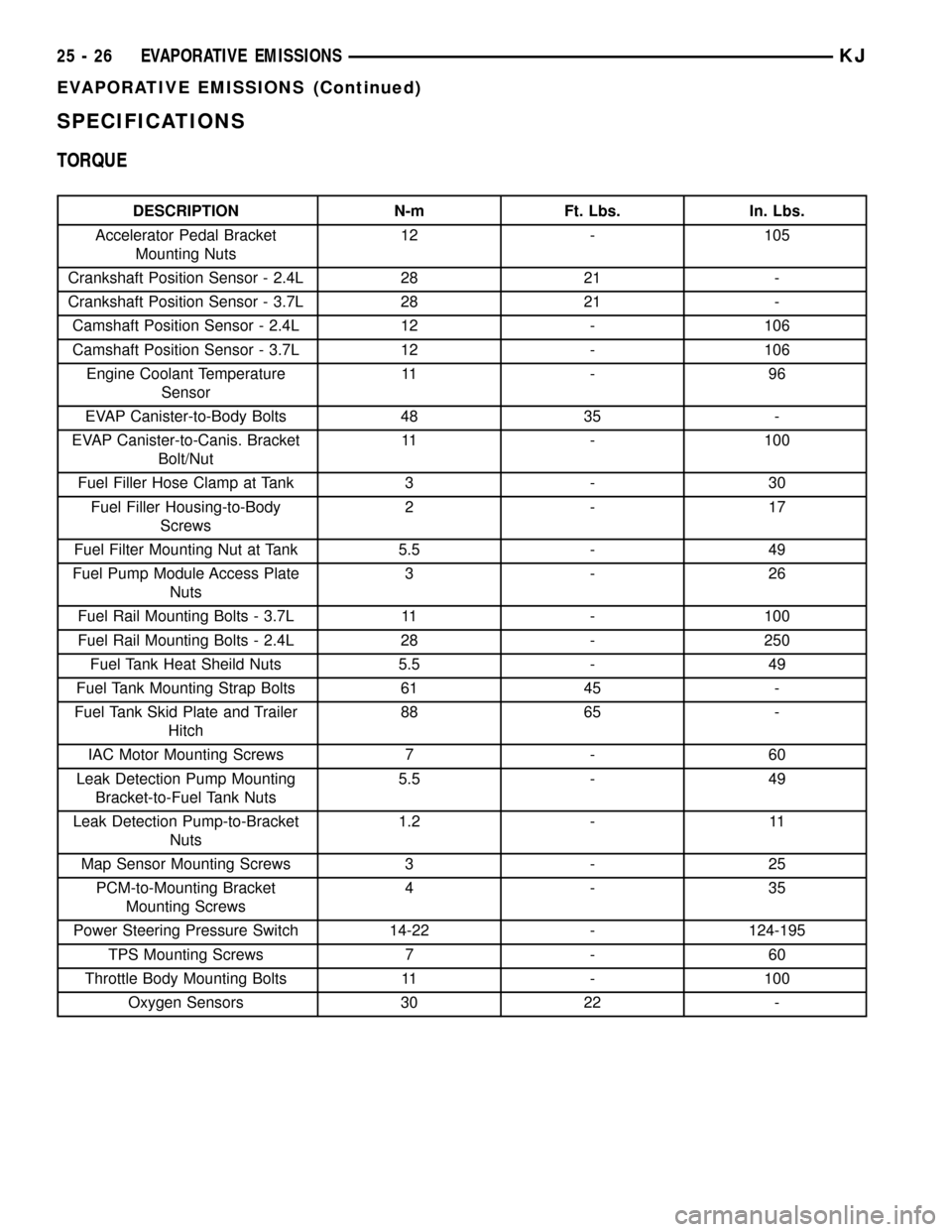
SPECIFICATIONS
TORQUE
DESCRIPTION N-m Ft. Lbs. In. Lbs.
Accelerator Pedal Bracket
Mounting Nuts12 - 105
Crankshaft Position Sensor - 2.4L 28 21 -
Crankshaft Position Sensor - 3.7L 28 21 -
Camshaft Position Sensor - 2.4L 12 - 106
Camshaft Position Sensor - 3.7L 12 - 106
Engine Coolant Temperature
Sensor11 - 9 6
EVAP Canister-to-Body Bolts 48 35 -
EVAP Canister-to-Canis. Bracket
Bolt/Nut11 - 100
Fuel Filler Hose Clamp at Tank 3 - 30
Fuel Filler Housing-to-Body
Screws2-17
Fuel Filter Mounting Nut at Tank 5.5 - 49
Fuel Pump Module Access Plate
Nuts3-26
Fuel Rail Mounting Bolts - 3.7L 11 - 100
Fuel Rail Mounting Bolts - 2.4L 28 - 250
Fuel Tank Heat Sheild Nuts 5.5 - 49
Fuel Tank Mounting Strap Bolts 61 45 -
Fuel Tank Skid Plate and Trailer
Hitch88 65 -
IAC Motor Mounting Screws 7 - 60
Leak Detection Pump Mounting
Bracket-to-Fuel Tank Nuts5.5 - 49
Leak Detection Pump-to-Bracket
Nuts1.2 - 11
Map Sensor Mounting Screws 3 - 25
PCM-to-Mounting Bracket
Mounting Screws4-35
Power Steering Pressure Switch 14-22 - 124-195
TPS Mounting Screws 7 - 60
Throttle Body Mounting Bolts 11 - 100
Oxygen Sensors 30 22 -
25 - 26 EVAPORATIVE EMISSIONSKJ
EVAPORATIVE EMISSIONS (Continued)
Page 1734 of 1803
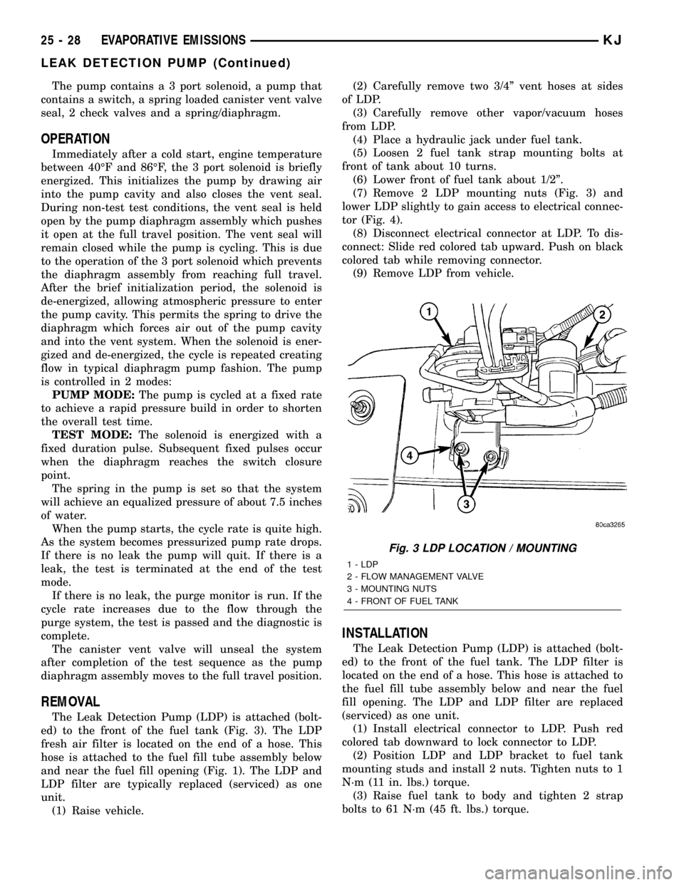
The pump contains a 3 port solenoid, a pump that
contains a switch, a spring loaded canister vent valve
seal, 2 check valves and a spring/diaphragm.
OPERATION
Immediately after a cold start, engine temperature
between 40ÉF and 86ÉF, the 3 port solenoid is briefly
energized. This initializes the pump by drawing air
into the pump cavity and also closes the vent seal.
During non-test test conditions, the vent seal is held
open by the pump diaphragm assembly which pushes
it open at the full travel position. The vent seal will
remain closed while the pump is cycling. This is due
to the operation of the 3 port solenoid which prevents
the diaphragm assembly from reaching full travel.
After the brief initialization period, the solenoid is
de-energized, allowing atmospheric pressure to enter
the pump cavity. This permits the spring to drive the
diaphragm which forces air out of the pump cavity
and into the vent system. When the solenoid is ener-
gized and de-energized, the cycle is repeated creating
flow in typical diaphragm pump fashion. The pump
is controlled in 2 modes:
PUMP MODE:The pump is cycled at a fixed rate
to achieve a rapid pressure build in order to shorten
the overall test time.
TEST MODE:The solenoid is energized with a
fixed duration pulse. Subsequent fixed pulses occur
when the diaphragm reaches the switch closure
point.
The spring in the pump is set so that the system
will achieve an equalized pressure of about 7.5 inches
of water.
When the pump starts, the cycle rate is quite high.
As the system becomes pressurized pump rate drops.
If there is no leak the pump will quit. If there is a
leak, the test is terminated at the end of the test
mode.
If there is no leak, the purge monitor is run. If the
cycle rate increases due to the flow through the
purge system, the test is passed and the diagnostic is
complete.
The canister vent valve will unseal the system
after completion of the test sequence as the pump
diaphragm assembly moves to the full travel position.
REMOVAL
The Leak Detection Pump (LDP) is attached (bolt-
ed) to the front of the fuel tank (Fig. 3). The LDP
fresh air filter is located on the end of a hose. This
hose is attached to the fuel fill tube assembly below
and near the fuel fill opening (Fig. 1). The LDP and
LDP filter are typically replaced (serviced) as one
unit.
(1) Raise vehicle.(2) Carefully remove two 3/4º vent hoses at sides
of LDP.
(3) Carefully remove other vapor/vacuum hoses
from LDP.
(4) Place a hydraulic jack under fuel tank.
(5) Loosen 2 fuel tank strap mounting bolts at
front of tank about 10 turns.
(6) Lower front of fuel tank about 1/2º.
(7) Remove 2 LDP mounting nuts (Fig. 3) and
lower LDP slightly to gain access to electrical connec-
tor (Fig. 4).
(8) Disconnect electrical connector at LDP. To dis-
connect: Slide red colored tab upward. Push on black
colored tab while removing connector.
(9) Remove LDP from vehicle.
INSTALLATION
The Leak Detection Pump (LDP) is attached (bolt-
ed) to the front of the fuel tank. The LDP filter is
located on the end of a hose. This hose is attached to
the fuel fill tube assembly below and near the fuel
fill opening. The LDP and LDP filter are replaced
(serviced) as one unit.
(1) Install electrical connector to LDP. Push red
colored tab downward to lock connector to LDP.
(2) Position LDP and LDP bracket to fuel tank
mounting studs and install 2 nuts. Tighten nuts to 1
N´m (11 in. lbs.) torque.
(3) Raise fuel tank to body and tighten 2 strap
bolts to 61 N´m (45 ft. lbs.) torque.
Fig. 3 LDP LOCATION / MOUNTING
1 - LDP
2 - FLOW MANAGEMENT VALVE
3 - MOUNTING NUTS
4 - FRONT OF FUEL TANK
25 - 28 EVAPORATIVE EMISSIONSKJ
LEAK DETECTION PUMP (Continued)