2002 JEEP LIBERTY rear door
[x] Cancel search: rear doorPage 12 of 1803

VEHICLE IDENTIFICATION NUMBER DECODING CHART
POSITION INTERPRETATION CODE = DESCRIPTION
1 Country of Origin 1 = United States
2 Make J = Jeep
3 Vehicle Type 4 = MPV W/O Side Airbags.
8 = MPV With Side Airbags.
4 Gross Vehicle Weight Rating F = 4001 - 5000 lbs.
G = 5001 - 6000 lbs.
5 Vehicle Line K = Liberty 4X2 (LHD)
L = Liberty 4X4 (LHD)
M = Cherokee 4X4 (RHD)
6 Series 3 = Liberty Renegade
4 = Liberty Sport/Cherokee Sport
5 = Liberty Limited/Cherokee Limited
7 Body Style 8 = Sport Utility - 4 Door
8 Engine K = 3.7L 6 cyl MPI Gasoline
1 = 2.4L 4 cyl MPI Gasoline
7 = 2.5L 4 cyl Diesel
9 Check Digit 0 through 9 or X
10 Model Year 2=2002
11 Assembly Plant W = Toledo North Assembly Plant
12 thru 17 Vehicle Build Sequence
VEHICLE SAFETY
CERTIFICATION LABEL
DESCRIPTION
A vehicle safety certification label (Fig. 6) is
attached to every DaimlerChrysler Corporation vehi-
cle. The label certifies that the vehicle conforms to all
applicable Federal Motor Vehicle Safety Standards.
The label also lists:
²Month and year of vehicle manufacture.
²Gross Vehicle Weight Rating (GVWR). The gross
front and rear axle weight ratings (GAWR's) arebased on a minimum rim size and maximum cold tire
inflation pressure.
²Vehicle Identification Number (VIN).
²Type of vehicle.
²Bar code.
²Month, Day and Hour (MDH) of final assembly.
²Paint and Trim codes.
²Country of origin.
The label is located above the door hinge on the
driver-side A-pillar.
Fig. 6 Vehicle Safety Certification LabelÐTypical
KJINTRODUCTION 9
VEHICLE IDENTIFICATION NUMBER (Continued)
Page 95 of 1803

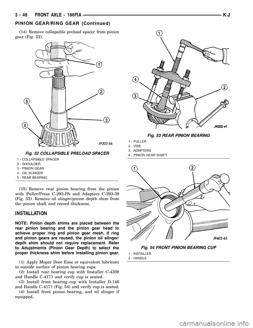
(14) Remove collapsible preload spacer from pinion
gear (Fig. 52).
(15) Remove rear pinion bearing from the pinion
with Puller/Press C-293-PA and Adapters C-293-39
(Fig. 53). Remove oil slinger/pinion depth shim from
the pinion shaft and record thickness.
INSTALLATION
NOTE: Pinion depth shims are placed between the
rear pinion bearing and the pinion gear head to
achieve proper ring and pinion gear mesh. If ring
and pinion gears are reused, the pinion oil slinger/
depth shim should not require replacement. Refer
to Adujstments (Pinion Gear Depth) to select the
proper thickness shim before installing pinion gear.
(1) Apply Mopar Door Ease or equivalent lubricant
to outside surface of pinion bearing cups.
(2) Install rear bearing cup with Installer C-4308
and Handle C-4171 and verify cup is seated.
(3) Install front bearing cup with Installer D-146
and Handle C-4171 (Fig. 54) and verify cup is seated.
(4) Install front pinion bearing, and oil slinger if
equipped.
Fig. 52 COLLAPSIBLE PRELOAD SPACER
1 - COLLAPSIBLE SPACER
2 - SHOULDER
3 - PINION GEAR
4 - OIL SLINGER
5 - REAR BEARING
Fig. 53 REAR PINION BEARING
1 - PULLER
2 - VISE
3 - ADAPTERS
4 - PINION GEAR SHAFT
Fig. 54 FRONT PINION BEARING CUP
1 - INSTALLER
2 - HANDLE
3 - 46 FRONT AXLE - 186FIAKJ
PINION GEAR/RING GEAR (Continued)
Page 131 of 1803

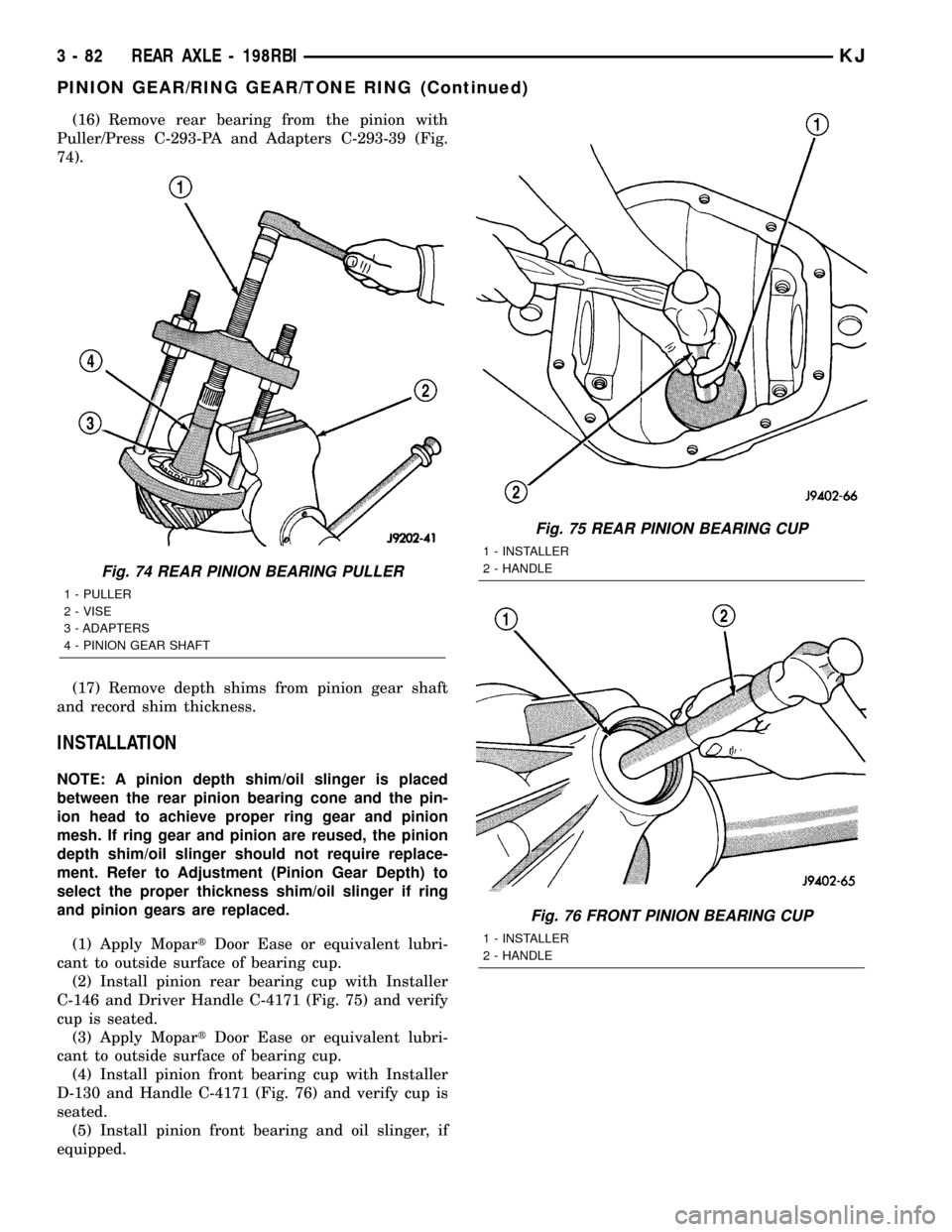
(16) Remove rear bearing from the pinion with
Puller/Press C-293-PA and Adapters C-293-39 (Fig.
74).
(17) Remove depth shims from pinion gear shaft
and record shim thickness.
INSTALLATION
NOTE: A pinion depth shim/oil slinger is placed
between the rear pinion bearing cone and the pin-
ion head to achieve proper ring gear and pinion
mesh. If ring gear and pinion are reused, the pinion
depth shim/oil slinger should not require replace-
ment. Refer to Adjustment (Pinion Gear Depth) to
select the proper thickness shim/oil slinger if ring
and pinion gears are replaced.
(1) Apply MopartDoor Ease or equivalent lubri-
cant to outside surface of bearing cup.
(2) Install pinion rear bearing cup with Installer
C-146 and Driver Handle C-4171 (Fig. 75) and verify
cup is seated.
(3) Apply MopartDoor Ease or equivalent lubri-
cant to outside surface of bearing cup.
(4) Install pinion front bearing cup with Installer
D-130 and Handle C-4171 (Fig. 76) and verify cup is
seated.
(5) Install pinion front bearing and oil slinger, if
equipped.
Fig. 74 REAR PINION BEARING PULLER
1 - PULLER
2 - VISE
3 - ADAPTERS
4 - PINION GEAR SHAFT
Fig. 75 REAR PINION BEARING CUP
1 - INSTALLER
2 - HANDLE
Fig. 76 FRONT PINION BEARING CUP
1 - INSTALLER
2 - HANDLE
3 - 82 REAR AXLE - 198RBIKJ
PINION GEAR/RING GEAR/TONE RING (Continued)
Page 161 of 1803

(10) Remove pinion shaft seal with a pry tool or
slide-hammer mounted screw.
(11) Remove oil slinger, if equipped, and front pin-
ion bearing.
(12) Remove front pinion bearing cup with
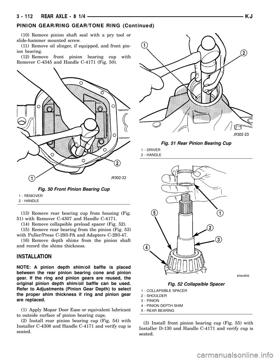
Remover C-4345 and Handle C-4171 (Fig. 50).
(13) Remove rear bearing cup from housing (Fig.
51) with Remover C-4307 and Handle C-4171.
(14) Remove collapsible preload spacer (Fig. 52).
(15) Remove rear bearing from the pinion (Fig. 53)
with Puller/Press C-293-PA and Adapters C-293-47.
(16) Remove depth shims from the pinion shaft
and record the shims thickness.
INSTALLATION
NOTE: A pinion depth shim/oil baffle is placed
between the rear pinion bearing cone and pinion
gear. If the ring and pinion gears are reused, the
original pinion depth shim/oil baffle can be used.
Refer to Adjustments (Pinion Gear Depth) to select
the proper shim thickness if ring and pinion gear
are replaced.
(1) Apply Mopar Door Ease or equivalent lubricant
to outside surface of pinion bearing cups.
(2) Install rear pinion bearing cup (Fig. 54) with
Installer C-4308 and Handle C-4171 and verify cup is
seated.(3) Install front pinion bearing cup (Fig. 55) with
Installer D-130 and Handle C-4171 and verify cup is
seated.
Fig. 50 Front Pinion Bearing Cup
1 - REMOVER
2 - HANDLE
Fig. 51 Rear Pinion Bearing Cup
1 - DRIVER
2 - HANDLE
Fig. 52 Collapsible Spacer
1 - COLLAPSIBLE SPACER
2 - SHOULDER
3 - PINION
4 - PINION DEPTH SHIM
5 - REAR BEARING
3 - 112 REAR AXLE-81/4KJ
PINION GEAR/RING GEAR/TONE RING (Continued)
Page 284 of 1803

(8) Install antenna mast.
(9) Tighten fender mounting bolts near door hinge
area.
(10) Install and tighten the upper fender mounting
bolts (Refer to 23 - BODY/EXTERIOR/FRONT
FENDER - INSTALLATION).
(11) Connect the battery negative cable.
CD CHANGER
DESCRIPTION
A factory-installed Compact Disc (CD) changer fea-
turing a six-CD magazine is an available option on
this model. The CD changer is mounted in the cargo
area of the passenger compartment on the right rear
quarter panel.
The controls on the radio receiver operate the CD
changer through messages sent over the Programma-
ble Communications Interface (PCI) data bus net-
work. For diagnosis of the messaging functions of the
radio receiver and the CD changer, or of the PCI data
bus, a DRB scan tool and the proper Diagnostic Pro-
cedures manual are required.
The CD changer can only be serviced by an autho-
rized radio repair station. See the latest Warranty
Policies and Procedures manual for a current listing
of authorized radio repair stations. Refer to the
appropriate wiring information. The wiring informa-
tion includes wiring diagrams, proper wire and con-
nector repair procedures, details of wire harness
routing and retention, connector pin-out information
and location views for the various wire harness con-
nectors, splices and grounds.
OPERATION
The CD changer will only operate when the igni-
tion switch is in the On or Accessory positions, and
the radio is turned on. The six-CD magazine may be
ejected with the ignition in the Off position. For more
information on the features, loading procedures and
radio control functions for the operation of the CD
changer, refer to the owner's manual.
REMOVAL
(1) Disconnect and isolate the battery negative
cable.
(2) Remove the right rear quarter trim panel.
(Refer to 23 - BODY/INTERIOR/QUARTER TRIM
PANEL - REMOVAL).
(3) Disconnect the electrical wire harness connec-
tor (Fig. 4).
(4) Remove the mounting nuts.
(5) Remove the CD Changer from the vehicle.
INSTALLATION
(1) Install the CD Changer to the vehicle.
(2) Install the mounting nuts. Tighten to 11.8 N´m
(104 in. lbs.).
(3) Connect the wire harness connector.
(4) Install the right rear quarter trim panel (Refer
to 23 - BODY/INTERIOR/QUARTER TRIM PANEL -
INSTALLATION).
(5) Connect the battery negative cable.
INSTRUMENT PANEL
ANTENNA CABLE
REMOVAL
WARNING: DISABLE THE AIRBAG SYSTEM
BEFORE ATTEMPTING ANY STEERING WHEEL,
STEERING COLUMN, SEAT BELT TENSIONER, SIDE
AIRBAG, OR INSTRUMENT PANEL COMPONENT
DIAGNOSIS OR SERVICE. DISCONNECT AND ISO-
LATE THE BATTERY NEGATIVE (GROUND) CABLE,
THEN WAIT TWO MINUTES FOR THE AIRBAG SYS-
TEM CAPACITOR TO DISCHARGE BEFORE PER-
FORMING FURTHER DIAGNOSIS OR SERVICE. THIS
IS THE ONLY SURE WAY TO DISABLE THE AIRBAG
SYSTEM. FAILURE TO TAKE THE PROPER PRE-
CAUTIONS COULD RESULT IN ACCIDENTAL AIR-
BAG DEPLOYMENT AND POSSIBLE PERSONAL
INJURY.
(1) Disconnect and isolate the battery negative
cable.
Fig. 4 CD CHANGER
1 - CD CHANGER
2 - WIRE HARNESS CONNECTOR
3 - MOUNTING NUT
KJAUDIO 8A - 7
ANTENNA BODY & CABLE (Continued)
Page 290 of 1803

ground. There should be no continuity. If OK, go to
Step 5. If not OK, repair the shorted remote radio
switch ground circuit to the BCM as required.
(5) Check for continuity between the remote radio
switch ground circuit cavities of the steering wheel
wire harness connectors for both remote radio
switches and the 22-way instrument panel wire har-
ness connector for the BCM. There should be conti-
nuity. If OK, refer to the proper Diagnostic
Procedures manual to test the BCM and the PCI
data bus. If not OK, repair the open remote radio
switch ground circuit as required.
REMOVAL
WARNING:DISABLE THE AIRBAG SYSTEM BEFORE
ATTEMPTING ANY STEERING WHEEL, STEERING
COLUMN, SEAT BELT TENSIONER, SIDE AIRBAG,
OR INSTRUMENT PANEL COMPONENT DIAGNOSIS
OR SERVICE. DISCONNECT AND ISOLATE THE BAT-
TERY NEGATIVE (GROUND) CABLE, THEN WAIT
TWO MINUTES FOR THE AIRBAG SYSTEM CAPACI-
TOR TO DISCHARGE BEFORE PERFORMING FUR-
THER DIAGNOSIS OR SERVICE. THIS IS THE ONLY
SURE WAY TO DISABLE THE AIRBAG SYSTEM.
FAILURE TO TAKE THE PROPER PRECAUTIONS
COULD RESULT IN ACCIDENTAL AIRBAG DEPLOY-
MENT AND POSSIBLE PERSONAL INJURY.
(1) Disconnect and isolate the battery negative
cable.
(2) Remove the driver side airbag module from the
vehicle (Refer to 8 - ELECTRICAL/RESTRAINTS/
DRIVER AIRBAG - REMOVAL).
(3) Remove the cruise control switches (Fig. 15).
(4) Unplug the wire harness connector from the
remote radio switch(es).
(5)
Depress the tabs on each side of each switch and
push the switch through the rear steering wheel cover.
INSTALLATION
WARNING:DISABLE THE AIRBAG SYSTEM BEFORE
ATTEMPTING ANY STEERING WHEEL, STEERING
COLUMN, SEAT BELT TENSIONER, SIDE AIRBAG,
OR INSTRUMENT PANEL COMPONENT DIAGNOSIS
OR SERVICE. DISCONNECT AND ISOLATE THE BAT-
TERY NEGATIVE (GROUND) CABLE, THEN WAIT
TWO MINUTES FOR THE AIRBAG SYSTEM CAPACI-
TOR TO DISCHARGE BEFORE PERFORMING FUR-
THER DIAGNOSIS OR SERVICE. THIS IS THE ONLY
SURE WAY TO DISABLE THE AIRBAG SYSTEM.
FAILURE TO TAKE THE PROPER PRECAUTIONS
COULD RESULT IN ACCIDENTAL AIRBAG DEPLOY-
MENT AND POSSIBLE PERSONAL INJURY.
(1) Install remote radio switch to the steering
wheel.(2) Connect the wire harness to the remote radio
switch.
(3) Install the cruise control switches.
(4) Install the driver side airbag module (Refer to
8 - ELECTRICAL/RESTRAINTS/DRIVER AIRBAG -
INSTALLATION).
(5) Connect the battery negative cable.
SPEAKER
DESCRIPTION
STANDARD
The standard equipment speaker system includes
speakers in six locations. One 6.4 centimeter (2.50
inch) diameter speaker is installed on each end of the
instrument panel top pad. One 16.5 centimeter (6.5
inch) full-range speaker is located in each front door.
There is also one full-range 16.5 centimeter (6.5 inch)
diameter full-range speaker located in each rear door.
PREMIUM
The optional premium speaker system features six
Premium model speakers in six locations. Each of the
standard speakers is replaced with Premium model
speakers. One 6.4 centimeter (2.50 inch) diameter
Fig. 15 REMOTE SWITCH
1 - STEERING WHEEL
2 - SPEED CONTROL SWITCH
3 - SCREW
4 - DRIVER SIDE AIRBAG MODULE
5 - REMOTE RADIO SWITCH
6 - REAR TRIM COVER
KJAUDIO 8A - 13
REMOTE SWITCHES (Continued)
Page 291 of 1803

speaker is installed on each end of the instrument
panel top pad. One 16.5 centimeter (6.5 inch) Pre-
mium woofer is located in each front door. There is
also one full-range 16.5 centimeter (6.5 inch) diame-
ter Premium full-range speaker located in each rear
door. The premium speaker system also includes a
power amplifier mounted to each front door speaker.
The total available power of the premium speaker
system is about 160 watts.
OPERATION
Two wires connected to each speaker, one feed cir-
cuit (+) and one return circuit (±), allow the audio
output signal electrical current to flow through the
voice coil. For complete circuit diagrams, refer to the
appropriate wiring information. The wiring informa-
tion includes wiring diagrams, proper wire and con-
nector repair procedures, details of wire harness
routing and retention, connector pin-out information
and location views for the various wire harness con-
nectors, splices and grounds.
REMOVAL
FRONT DOOR
(1) Disconnect and isolate the battery negative
cable.
(2) Remove the front door trim panel (Refer to 23 -
BODY/DOOR - FRONT/TRIM PANEL - REMOVAL).
(3) Remove the speaker mounting screws (Fig. 16).
(4) Remove the speaker from the door and discon-
nect the wire harness connector.
INSTRUMENT PANEL
(1) Disconnect and isolate the battery negative
cable.
(2) Remove the A-pillar trim (Refer to 23 - BODY/
INTERIOR/A-PILLAR TRIM - REMOVAL).
(3) Remove instrument panel top cover (Refer to
23 - BODY/INSTRUMENT PANEL/INSTRUMENT
PANEL TOP COVER - REMOVAL).
(4) Remove speaker mounting screws (Fig. 17).
(5) Remove speaker and disconnect the wire har-
ness connector.
Fig. 16 FRONT DOOR SPEAKER
1 - FRONT DOOR SPEAKER
2 - MOUNTING SCREW
3 - WIRE HARNESS CONNECTOR
Fig. 17 INSTRUMENT PANEL SPEAKER
1 - INSTRUMENT PANEL SPEAKER
2 - INSTRUMENT PANEL
8A - 14 AUDIOKJ
SPEAKER (Continued)
Page 292 of 1803

REAR DOOR
(1) Disconnect and isolate the battery negative
cable.
(2) Remove the rear door trim panel (Refer to 23 -
BODY/DOORS - REAR/TRIM PANEL - REMOVAL).
(3) Remove the speaker mounting screws (Fig. 18).
(4) Remove the speaker from the door and discon-
nect the wire harness connector.
INSTALLATION
FRONT DOOR
(1) Connect the wire harness connector and install
the speaker to the door.
(2) Install the speaker mounting screws. Tighten
to 2 N´m (20 in. lbs.).
(3) Install the front door trim panel (Refer to 23 -
BODY/DOOR - FRONT/TRIM PANEL - INSTALLA-
TION).
(4) Connect the battery negative cable.
INSTRUMENT PANEL
(1) Connect wire harness connector and install
speaker.
(2) Install speaker mounting screws. Tighten to 2
N´m (20 in. lbs.).
(3) Install instrument panel top cover (Refer to 23
- BODY/INSTRUMENT PANEL/INSTRUMENT
PANEL TOP COVER - INSTALLATION).
(4) Install the A-pillar trim (Refer to 23 - BODY/
INTERIOR/A-PILLAR TRIM - INSTALLATION).
(5) Connect the battery negative cable.
REAR DOOR
(1) Connect the wire harness connector and install
the speaker to the door.
(2) Install the speaker mounting screws. Tighten
to 2 N´m (20 in. lbs.).
(3) Install the rear door trim panel (Refer to 23 -
BODY/DOORS - REAR/TRIM PANEL - INSTALLA-
TION).
(4) Connect the battery negative cable.
Fig. 18 REAR DOOR SPEAKER
1 - REAR DOOR SPEAKER
2 - MOUNTING SCREW
3 - WIRE HARNESS CONNECTOR
KJAUDIO 8A - 15
SPEAKER (Continued)