2002 JEEP LIBERTY Tighten timing chain
[x] Cancel search: Tighten timing chainPage 232 of 1803

CONDITION POSSIBLE CAUSES CORRECTION
BELT BROKEN (NOTE: IDENTIFY
AND CORRECT PROBLEM
BEFORE NEW BELT IS
INSTALLED)1. Excessive tension. 1. Replace belt and automatic belt
tensioner.
2. Incorrect belt. 2. Replace belt.
3. Tensile member damaged during
belt installation.3. Replace belt.
4. Severe misalignment. 4. Check and replace.
5. Bracket, pulley, or bearing failure. 5. Replace defective component
and belt.
NOISE (OBJECTIONABLE
SQUEAL, SQUEAK, OR RUMBLE
IS HEARD OR FELT WHILE
DRIVE BELT IS IN OPERATION)1. Belt slippage. 1. Replace belt or automatic belt
tensioner.
2. Bearing noise. 2. Locate and repair.
3. Belt misalignment. 3. Replace belt.
4. Belt-to-pulley mismatch. 4. Install correct belt.
BELT TENSIONERS
REMOVAL - 3.7L ENGINE
(1) Remove accessory drive belt (Refer to 7 -
COOLING/ACCESSORY DRIVE/DRIVE BELTS -
REMOVAL).
(2) Remove tensioner assembly from engine front
cover (Fig. 2).WARNING: BECAUSE OF HIGH SPRING TENSION,
DO NOT ATTEMPT TO DISASSEMBLE AUTOMATIC
TENSIONER. UNIT IS SERVICED AS AN ASSEMBLY
(EXCEPT FOR PULLEY ON TENSIONER).
(3) Remove pulley bolt. Remove pulley from ten-
sioner.
INSTALLATION - 3.7L ENGINE
(1) Install pulley and pulley bolt to tensioner.
Tighten bolt to 61 N´m (45 ft. lbs.) torque.
(2) An indexing slot is located on back of tensioner.
Align this slot to the head of the bolt on the front
cover. Install the mounting bolt. Tighten bolt to 41
N´m (30 ft. lbs.).
(3) Install drive belt (Refer to 7 - COOLING/AC-
CESSORY DRIVE/DRIVE BELTS - INSTALLA-
TION).
(4) Check belt indexing marks (Refer to 7 - COOL-
ING/ACCESSORY DRIVE/DRIVE BELTS - INSTAL-
LATION).
DRIVE BELTS - 3.7L
REMOVAL - 3.7L ENGINE
NOTE: The belt routing schematics are published
from the latest information available at the time of
publication. If anything differs between these sche-
matics and the Belt Routing Label, use the sche-
matics on Belt Routing Label. This label is located
in the engine compartment.
Fig. 2 Automatic Belt Tensioner
1 - TIMING CHAIN COVER
2 - BOLT TORQUE TO 41 N´m (30 FT LBS)
3 - AUTOMATIC BELT TENSIONER
KJACCESSORY DRIVE 7 - 17
ACCESSORY DRIVE (Continued)
Page 237 of 1803

INSTALLATION - 3.7L ENGINE
(1) Clean mating areas of timing chain cover and
thermostat housing.
(2)
Install thermostat (spring side down) into
recessed machined groove on timing chain cover (Fig. 4).
(3) Position thermostat housing on timing chain
cover.
(4) Install two housing-to-timing chain cover bolts.
Tighten bolts to 13 N´m (115 in. lbs.) torque.
CAUTION: Housing must be tightened evenly and
thermostat must be centered into recessed groove
in timimg chain cover. If not, it may result in a
cracked housing, damaged timing chain cover
threads or coolant leaks.
(5)
Install lower radiator hose on thermostat housing.
(6) Install splash shield.
(7) Lower vehicle.
(8) Fill cooling system (Refer to 7 - COOLING -
STANDARD PROCEDURE).
(9) Connect negative battery cable to battery.
(10) Start and warm the engine. Check for leaks.
RADIATOR
DESCRIPTION
All vehicles are equipped with a cross flow type
radiator with plastic side tanks (Fig. 5).Plastic tanks, while stronger than brass, are sub-
ject to damage by impact, such as from tools or
wrenches. Handle radiator with care.
Fig. 4 Thermostat and Thermostat Housing
1 - THERMOSTAT HOUSING
2 - THERMOSTAT LOCATION3 - THERMOSTAT AND GASKET
4 - TIMING CHAIN COVER
Fig. 5 Cross Flow Radiator - Typical
1 - RADIATOR
7 - 22 ENGINEKJ
ENGINE COOLANT THERMOSTAT (Continued)
Page 244 of 1803

CAUTION: Do not remove water pump pulley-to-wa-
ter pump bolts. This pulley is under belt tension.
(8) Remove four bolts securing fan blade assembly
to viscous fan drive.
CLEANING
Clean the fan blades using a mild soap and water.
Do not use an abrasive to clean the blades.
INSPECTION
WARNING: DO NOT ATTEMPT TO BEND OR
STRAIGHTEN FAN BLADES IF FAN IS NOT WITHIN
SPECIFICATIONS.
CAUTION: If fan blade assembly is replaced
because of mechanical damage, water pump and
viscous fan drive should also be inspected. These
components could have been damaged due to
excessive vibration.
(1) Remove fan blade assembly from viscous fan
drive unit (four bolts).
(2) Lay fan on a flat surface with leading edge fac-
ing down. With tip of blade touching flat surface,
replace fan if clearance between opposite blade and
surface is greater than 2.0 mm (.090 inch). Rocking
motion of opposite blades should not exceed 2.0 mm
(.090 inch). Test all blades in this manner.
(3) Inspect fan assembly for cracks, bends, loose
rivets or broken welds. Replace fan if any damage is
found.
INSTALLATION
(1) Assemble fan blade to viscous fan drive.
Tighten mounting bolts to 27 N´m (20 ft. lbs.) torque.
NOTE: The vicous fan and fan shroud must be
installed as an assembly.
(2) Gently lay vicous fan into fan shroud.
(3) Install the fan shroud to radiator mounting
bolts, torque bolts to (5.5N´M or 50 in´lbs).
(4) Thread the fan and fan drive onto the water
pump pulley, and tighten nut using special tool 6958
spanner wrench and 8346 adapters.
(5) Connect the electrical connector for the electric
fan.
CAUTION: When installing a serpentine accessory
drive belt, the belt MUST be routed correctly. If not,
the engine may overheat due to the water pump
rotating in the wrong direction. (Refer to 7 - COOL-
ING/ACCESSORY DRIVE/DRIVE BELTS - REMOVAL)
for correct belt routing.
WATER PUMP
DESCRIPTION
DESCRIPTION - WATER PUMP
A centrifugal water pump circulates coolant
through the water jackets, passages, intake manifold,
radiator core, cooling system hoses and heater core.
The pump is driven from the engine crankshaft by a
single serpentine drive belt.
The water pump impeller is pressed onto the rear
of a shaft that rotates in bearings pressed into the
housing. The housing has two small holes to allow
seepage to escape. The water pump seals are lubri-
cated by the antifreeze in the coolant mixture. No
additional lubrication is necessary.
Both heater hoses are connected to fittings on the
timing chain front cover. The water pump is also
mounted directly to the timing chain cover and is
equipped with a non serviceable integral pulley (Fig.
17).
DESCRIPTION
The 3.7L engine uses an internal water/coolant
bypass system. The design uses galleries in the tim-
ing chain cover to circulate coolant during engine
warm-up preventing the coolant from flowing
Fig. 17 Water Pump and Timing Chain Cover
1 - INTEGRAL WATER PUMP PULLEY
2 - TIMING CHAIN COVER
3 - THERMOSTAT HOUSING
4 - HEATER HOSE FITTINGS
5 - WATER PUMP
KJENGINE 7 - 29
RADIATOR - FAN - VISCOUS (Continued)
Page 246 of 1803

CAUTION: Do not pry water pump at timing chain
case/cover. The machined surfaces may be dam-
aged resulting in leaks.
(11) Remove water pump and gasket. Discard gas-
ket.
CLEANING
Clean the gasket mating surface. Use caution not
to damage the gasket sealing surface.
INSPECTION
Inspect the water pump assembly for cracks in the
housing, Water leaks from shaft seal, Loose or rough
turning bearing or Impeller rubbing either the pump
body or timing chain case/cover.
INSTALLATION
The water pump on 3.7L engines is bolted directly
to the engine timing chain case cover.
(1) Clean gasket mating surfaces.
(2) Using a new gasket, position water pump and
install mounting bolts as shown. (Fig. 20). Tighten
water pump mounting bolts to 54 N´m (40 ft. lbs.)
torque.
(3) Spin water pump to be sure that pump impel-
ler does not rub against timing chain case/cover.
(4) Connect radiator lower hose to water pump.
(5) Relax tension from belt tensioner. Install drive
belt (Refer to 7 - COOLING/ACCESSORY DRIVE/
DRIVE BELTS - INSTALLATION).CAUTION: When installing the serpentine accessory
drive belt, belt must be routed correctly. If not,
engine may overheat due to water pump rotating in
wrong direction. Refer to (Fig. 21) for correct belt
routing. Or, refer to the Belt Routing Label located
in the engine compartment. The correct belt with
correct length must be used.
(6) Position upper fan shroud and fan blade/vis-
cous fan drive assembly.
(7) Be sure the upper and lower portions of the fan
shroud are firmly connected. All air must flow
through the radiator.
(8) Install two fan shroud-to-radiator screws.
(9) Be sure of at least 25 mm (1.0 inches) between
tips of fan blades and fan shroud.
(10) Install fan blade/viscous fan drive assembly to
water pump shaft (Refer to 7 - COOLING/ENGINE/
FAN DRIVE VISCOUS CLUTCH - INSTALLATION).
(11) Fill cooling system (Refer to 7 - COOLING -
STANDARD PROCEDURE).
(12) Connect negative battery cable.
(13) Start and warm the engine. Check for leaks.
Fig. 20 Water Pump InstallationÐ3.7L
1 - WATER PUMP
2 - TIMING CHAIN COVER
Fig. 21 Belt Routing 3.7L
1 - GENERATOR PULLEY
2 - ACCESSORY DRIVE BELT
3 - POWER STEERING PUMP PULLEY
4 - CRANKSHAFT PULLEY
5 - IDLER PULLEY
6 - TENSIONER
7 - A/C COMPRESSOR PULLEY
8 - WATER PUMP PULLEY
KJENGINE 7 - 31
WATER PUMP (Continued)
Page 1222 of 1803

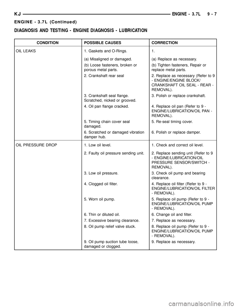
DIAGNOSIS AND TESTING - ENGINE DIAGNOSIS - LUBRICATION
CONDITION POSSIBLE CAUSES CORRECTION
OIL LEAKS 1. Gaskets and O-Rings. 1.
(a) Misaligned or damaged. (a) Replace as necessary.
(b) Loose fasteners, broken or
porous metal parts.(b) Tighten fasteners, Repair or
replace metal parts.
2. Crankshaft rear seal 2. Replace as necessary (Refer to 9
- ENGINE/ENGINE BLOCK/
CRANKSHAFT OIL SEAL - REAR -
REMOVAL).
3. Crankshaft seal flange.
Scratched, nicked or grooved.3. Polish or replace crankshaft.
4. Oil pan flange cracked. 4. Replace oil pan (Refer to 9 -
ENGINE/LUBRICATION/OIL PAN -
REMOVAL).
5. Timing chain cover seal
damaged.5. Re-seal timing cover.
6. Scratched or damaged vibration
damper hub.6. Polish or replace damper.
OIL PRESSURE DROP 1. Low oil level. 1. Check and correct oil level.
2. Faulty oil pressure sending unit. 2. Replace sending unit (Refer to 9
- ENGINE/LUBRICATION/OIL
PRESSURE SENSOR/SWITCH -
REMOVAL).
3. Low oil pressure. 3. Check oil pump and bearing
clearance.
4. Clogged oil filter. 4. Replace oil filter (Refer to 9 -
ENGINE/LUBRICATION/OIL FILTER
- REMOVAL).
5. Worn oil pump. 5. Replace oil pump (Refer to 9 -
ENGINE/LUBRICATION/OIL PUMP
- REMOVAL).
6. Thin or diluted oil. 6. Change oil and filter.
7. Excessive bearing clearance. 7. Replace as necessary.
8. Oil pump relief valve stuck. 8. Replace oil pump (Refer to 9 -
ENGINE/LUBRICATION/OIL PUMP
- REMOVAL).
9. Oil pump suction tube loose,
damaged or clogged.9. Replace as necessary.
KJENGINE - 3.7L 9 - 7
ENGINE - 3.7L (Continued)
Page 1227 of 1803

(35) Install the mechanical cooling fan.
(36) Install the fan shroud with the electric fan
assembly.
(37) Install the radiator core support bracket.
(38) Install the air cleaner assembly.
(39) Refill the engine cooling system.
(40) Install the hood.
(41) Check and fill engine oil.
(42) Connect the battery negative cable.
(43) Start the engine and check for leaks.
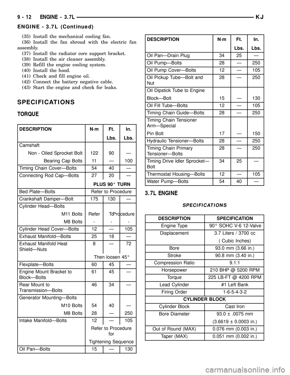
SPECIFICATIONS
TORQUE
DESCRIPTION N´m Ft. In.
Lbs. Lbs.
Camshaft
Non - Oiled Sprocket Bolt 122 90 Ð
Bearing Cap Bolts 11 Ð 100
Timing Chain CoverÐBolts 54 40 Ð
Connecting Rod CapÐBolts 27 20 Ð
PLUS 90É TURN
Bed PlateÐBolts Refer to Procedure
Crankshaft DamperÐBolt 175 130 Ð
Cylinder HeadÐBolts
M11 Bolts Refer ToProcedure
M8 Bolts - - -
Cylinder Head CoverÐBolts 12 Ð 105
Exhaust ManifoldÐBolts 25 18 Ð
Exhaust Manifold Heat
ShieldÐNuts8Ð72
Then loosen 45É
FlexplateÐBolts 60 45 Ð
Engine Mount Bracket to
BlockÐBolts61 45 Ð
Rear Mount to
TransmissionÐBolts46 34 Ð
Generator MountingÐBolts
M10 Bolts 54 40 Ð
M8 Bolts 28 Ð 250
Intake ManifoldÐBolts 12 Ð 105
Refer to Procedure
for
Tightening Sequence
Oil PanÐBolts 15 Ð 130
DESCRIPTION N´m Ft. In.
Lbs. Lbs.
Oil PanÐDrain Plug 34 25 Ð
Oil PumpÐBolts 28 Ð 250
Oil Pump CoverÐBolts 12 Ð 105
Oil Pickup TubeÐBolt and
Nut28 Ð 250
Oil Dipstick Tube to Engine
BlockÐBolt 15 Ð 130
Oil Fill TubeÐBolts 12 Ð 105
Timing Chain GuideÐBolts 28 Ð 250
Timing Chain Tensioner
ArmÐSpecial
Pin Bolt 17 Ð 150
Hydraulic TensionerÐBolts 28 Ð 250
Timing Chain Primary
TensionerÐBolts28 Ð 250
Timing Drive Idler SprocketÐ
Bolt34 25 Ð
Thermostat HousingÐBolts 12 Ð 105
Water PumpÐBolts 54 40 Ð
3.7L ENGINE
SPECIFICATIONS
DESCRIPTION SPECIFICATION
Engine Type 90É SOHC V-6 12-Valve
Displacement 3.7 Liters / 3700 cc
( Cubic Inches)
Bore 93.0 mm (3.66 in.)
Stroke 90.8 mm (3.40 in.)
Compression Ratio 9.1:1
Horsepower 210 BHP @ 5200 RPM
Torque 225 LB-FT @ 4200 RPM
Lead Cylinder #1 Left Bank
Firing Order 1-6-5-4-3-2
CYLINDER BLOCK
Cylinder Block Cast Iron
Bore Diameter 93.0 .0075 mm
(3.6619 0.0003 in.)
Out of Round (MAX) 0.076 mm (0.003 in.)
Taper (MAX) 0.051 mm (0.002 in.)
9 - 12 ENGINE - 3.7LKJ
ENGINE - 3.7L (Continued)
Page 1238 of 1803

(4) Lubricate the cylinder head bolt threads with
clean engine oil and install the eight M11 bolts.
(5) Coat the four M8 cylinder head bolts with
MopartLock and Seal Adhesivethen install the
bolts.
NOTE: The cylinder head bolts are tightened using
an angle torque procedure, however, the bolts are
not a torque-to-yield design.
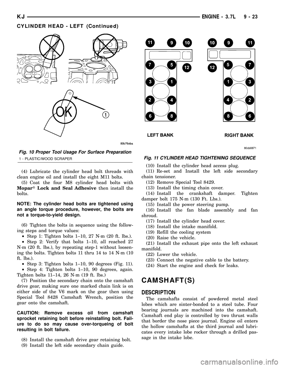
(6) Tighten the bolts in sequence using the follow-
ing steps and torque values:
²Step 1: Tighten bolts 1±10, 27 N´m (20 ft. lbs.).
²Step 2: Verify that bolts 1±10, all reached 27
N´m (20 ft. lbs.), by repeating step-1 without loosen-
ing the bolts. Tighten bolts 11 thru 14 to 14 N´m (10
ft. lbs.).
²Step 3: Tighten bolts 1±10, 90 degrees (Fig. 11).
²Step 4: Tighten bolts 1±10, 90 degrees, again.
Tighten bolts 11±14, 26 N´m (19 ft. lbs.)
(7) Position the secondary chain onto the camshaft
drive gear, making sure one marked chain link is on
either side of the V6 mark on the gear then using
Special Tool 8428 Camshaft Wrench, position the
gear onto the camshaft.
CAUTION: Remove excess oil from camshaft
sprocket retaining bolt before reinstalling bolt. Fail-
ure to do so may cause over-torqueing of bolt
resulting in bolt failure.
(8) Install the camshaft drive gear retaining bolt.
(9) Install the left side secondary chain guide.(10) Install the cylinder head access plug.
(11) Re-set and Install the left side secondary
chain tensioner.
(12) Remove Special Tool 8429.
(13) Install the timing chain cover.
(14) Install the crankshaft damper. Tighten
damper bolt 175 N´m (130 Ft. Lbs.).
(15) Install the power steering pump.
(16) Install the fan blade assembly and fan
shroud.
(17) Install the cylinder head cover.
(18) Install the intake manifold.
(19) Refill the cooling system
(20) Raise the vehicle.
(21) Install the exhaust pipe onto the left exhaust
manifold.
(22) Lower the vehicle.
(23) Connect the negative cable to the battery.
(24) Start the engine and check for leaks.
CAMSHAFT(S)
DESCRIPTION
The camshafts consist of powdered metal steel
lobes which are sinter-bonded to a steel tube. Four
bearing journals are machined into the camshaft.
Camshaft end play is controlled by two thrust walls
that border the nose piece journal. Engine oil enters
the hollow camshafts at the third journal and lubri-
cates every intake lobe rocker through a drilled pas-
sage in the intake lobe.
Fig. 10 Proper Tool Usage For Surface Preparation
1 - PLASTIC/WOOD SCRAPERFig. 11 CYLINDER HEAD TIGHTENING SEQUENCE
KJENGINE - 3.7L 9 - 23
CYLINDER HEAD - LEFT (Continued)
Page 1240 of 1803

NOTE: When the camshaft is removed the rocker
arms may slide downward, mark the rocker arms
before removing camshaft.
(9) Remove the camshaft bearing caps and the
camshaft.
INSTALLATION
(1) Lubricate camshaft journals with clean engine
oil.
NOTE: Position the left side camshaft so that the
camshaft sprocket dowel is near the 1 o'clock posi-
tion, This will place the camshaft at the neutral
position easing the installation of the camshaft
bearing caps.
(2) Position the camshaft into the cylinder head.
(3) Install the camshaft bearing caps, hand tighten
the retaining bolts.
NOTE: Caps should be installed so that the
stamped numbers on the caps are in numerical
order, ( 1 thru 4 ) from the front to the rear of the
engine. All caps should be installed so that the
stamped arrows on the caps point toward the front
of the engine.
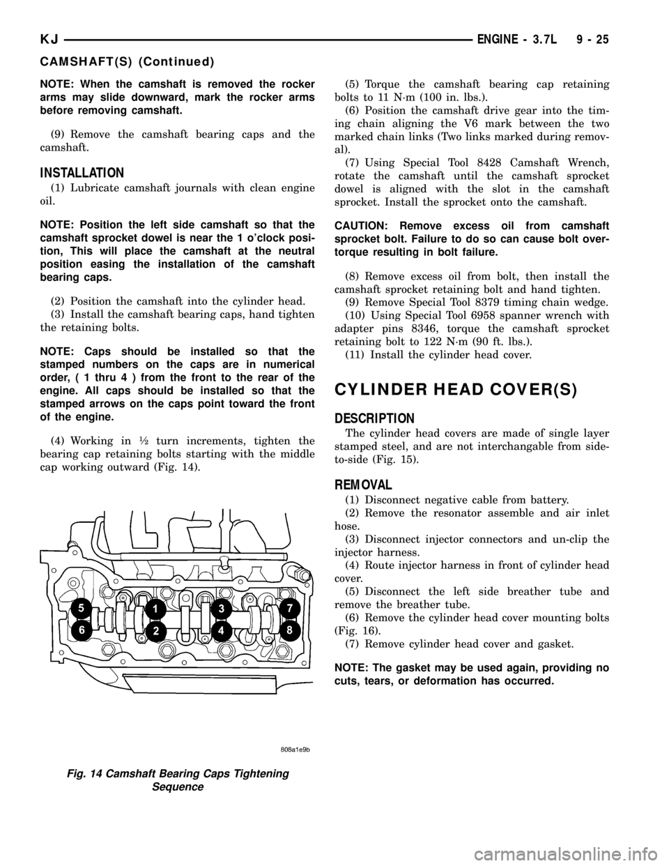
(4) Working in ó turn increments, tighten the
bearing cap retaining bolts starting with the middle
cap working outward (Fig. 14).(5) Torque the camshaft bearing cap retaining
bolts to 11 N´m (100 in. lbs.).
(6) Position the camshaft drive gear into the tim-
ing chain aligning the V6 mark between the two
marked chain links (Two links marked during remov-
al).
(7) Using Special Tool 8428 Camshaft Wrench,
rotate the camshaft until the camshaft sprocket
dowel is aligned with the slot in the camshaft
sprocket. Install the sprocket onto the camshaft.
CAUTION: Remove excess oil from camshaft
sprocket bolt. Failure to do so can cause bolt over-
torque resulting in bolt failure.
(8) Remove excess oil from bolt, then install the
camshaft sprocket retaining bolt and hand tighten.
(9) Remove Special Tool 8379 timing chain wedge.
(10) Using Special Tool 6958 spanner wrench with
adapter pins 8346, torque the camshaft sprocket
retaining bolt to 122 N´m (90 ft. lbs.).
(11) Install the cylinder head cover.
CYLINDER HEAD COVER(S)
DESCRIPTION
The cylinder head covers are made of single layer
stamped steel, and are not interchangable from side-
to-side (Fig. 15).
REMOVAL
(1) Disconnect negative cable from battery.
(2) Remove the resonator assemble and air inlet
hose.
(3) Disconnect injector connectors and un-clip the
injector harness.
(4) Route injector harness in front of cylinder head
cover.
(5) Disconnect the left side breather tube and
remove the breather tube.
(6) Remove the cylinder head cover mounting bolts
(Fig. 16).
(7) Remove cylinder head cover and gasket.
NOTE: The gasket may be used again, providing no
cuts, tears, or deformation has occurred.
Fig. 14 Camshaft Bearing Caps Tightening
Sequence
KJENGINE - 3.7L 9 - 25
CAMSHAFT(S) (Continued)