Page 98 of 1803

REAR AXLE - 198RBI
TABLE OF CONTENTS
page page
REAR AXLE - 198RBI
DESCRIPTION.........................49
OPERATION...........................49
DIAGNOSIS AND TESTING - AXLE..........51
REMOVAL.............................54
INSTALLATION.........................54
ADJUSTMENTS
ADJUSTMENT........................55
SPECIFICATIONS - REAR AXLE............62
SPECIAL TOOLS
REAR AXLE..........................63
AXLE SHAFTS
REMOVAL.............................65
INSTALLATION.........................65
AXLE BEARING/SEAL
REMOVAL.............................66
INSTALLATION.........................67
PINION SEAL
REMOVAL.............................68INSTALLATION.........................68
COLLAPSIBLE SPACER
REMOVAL.............................70
INSTALLATION.........................70
DIFFERENTIAL
REMOVAL.............................71
INSTALLATION.........................73
DIFFERENTIAL - TRAC-LOK
DIAGNOSIS AND TESTING - TRAC-LOKT.....74
DISASSEMBLY.........................75
CLEANING............................77
INSPECTION..........................77
ASSEMBLY............................77
DIFFERENTIAL CASE BEARINGS
REMOVAL.............................79
INSTALLATION.........................79
PINION GEAR/RING GEAR/TONE RING
REMOVAL.............................79
INSTALLATION.........................82
REAR AXLE - 198RBI
DESCRIPTION
The Rear Beam-design Iron (RBI) axle housing has
an iron center casting (differential housing) with axle
shaft tubes extending from either side. The tubes are
pressed into and welded to the differential housing to
form a one-piece axle housing. The axles are
equipped with semi±floating axle shafts, meaning
that loads are supported by the axle shaft and bear-
ings. The axle shafts are retained by the unit bear-
ing, retainer plate and bolts.
The integral type, hypoid gear design, housing has
the centerline of the pinion set below the centerline
of the ring gear. The differential case is a one-piece
design. The differential pinion mate shaft is retained
with a threaded screw. Differential bearing preload
and ring gear backlash is adjusted by the use of
selective spacer shims. Pinion bearing preload is set
and maintained by the use of a collapsible spacer
(Fig. 1).
The cover provides a means for servicing the differ-
ential without removing the axle. The axle has a vent
hose to relieve internal pressure caused by lubricant
vaporization and internal expansion.
Axles equipped with a Trac-Loktdifferential are
optional. A Trac-Loktdifferential has a one-piece dif-ferential case, and the same internal components as
a standard differential, plus two clutch disc packs.
OPERATION
The axle receives power from the transmission/
transfer case through the rear propeller shaft. The
Fig. 1 SHIM LOCATIONS
1 - PINION GEAR DEPTH SHIM
2 - DIFFERENTIAL BEARING SHIM-PINION GEAR SIDE
3 - RING GEAR
4 - DIFFERENTIAL BEARING SHIM-RING GEAR SIDE
5 - COLLAPSIBLE SPACER
KJREAR AXLE - 198RBI 3 - 49
Page 128 of 1803

DIFFERENTIAL CASE
BEARINGS
REMOVAL
(1) Remove differential case from axle housing.
(2) Remove side bearings from the differential case
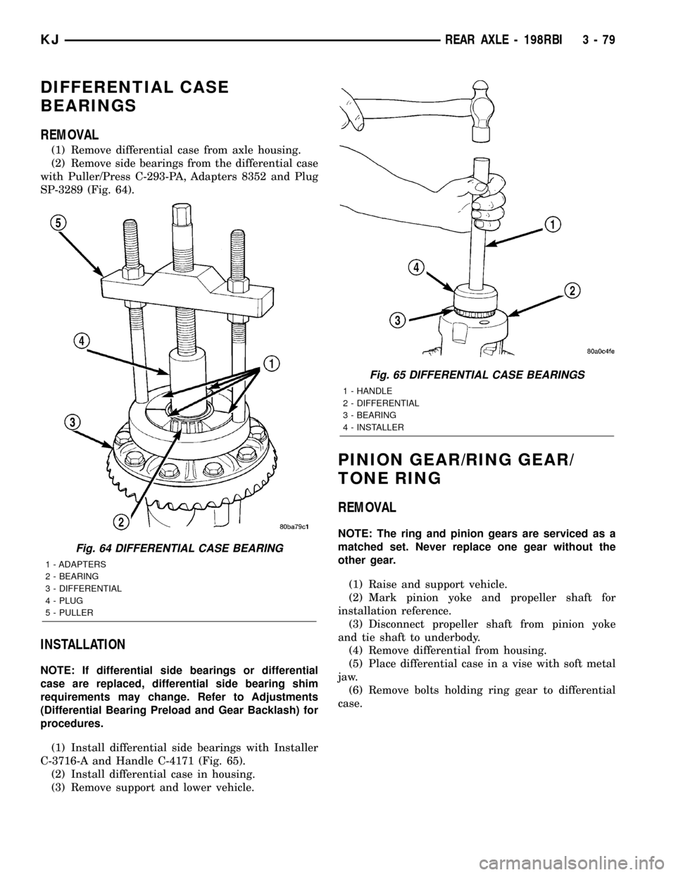
with Puller/Press C-293-PA, Adapters 8352 and Plug
SP-3289 (Fig. 64).
INSTALLATION
NOTE: If differential side bearings or differential
case are replaced, differential side bearing shim
requirements may change. Refer to Adjustments
(Differential Bearing Preload and Gear Backlash) for
procedures.
(1) Install differential side bearings with Installer
C-3716-A and Handle C-4171 (Fig. 65).
(2) Install differential case in housing.
(3) Remove support and lower vehicle.
PINION GEAR/RING GEAR/
TONE RING
REMOVAL
NOTE: The ring and pinion gears are serviced as a
matched set. Never replace one gear without the
other gear.
(1) Raise and support vehicle.
(2) Mark pinion yoke and propeller shaft for
installation reference.
(3) Disconnect propeller shaft from pinion yoke
and tie shaft to underbody.
(4) Remove differential from housing.
(5) Place differential case in a vise with soft metal
jaw.
(6) Remove bolts holding ring gear to differential
case.
Fig. 64 DIFFERENTIAL CASE BEARING
1 - ADAPTERS
2 - BEARING
3 - DIFFERENTIAL
4 - PLUG
5 - PULLER
Fig. 65 DIFFERENTIAL CASE BEARINGS
1 - HANDLE
2 - DIFFERENTIAL
3 - BEARING
4 - INSTALLER
KJREAR AXLE - 198RBI 3 - 79
Page 129 of 1803
(7) Drive ring gear from differential case with a
rawhide hammer (Fig. 66).
(8) Hold pinion yoke with Spanner Wrench 6958
and remove pinion yoke nut and washer (Fig. 67).(9) Remove pinion yoke from pinion shaft with
Remover C-452 and Wrench C-3281 (Fig. 68).
(10) Remove pinion gear from housing (Fig. 69).
Fig. 66 RING GEAR
1 - DIFFERENTIAL CASE
2 - RING GEAR
3 - RAWHIDE HAMMER
Fig. 67 YOKE SPANNER WRENCH
1 - PINION YOKE
2 - WRENCH
3 - PIPE
Fig. 68 PINION YOKE REMOVER
1 - WRENCH
2 - YOKE
3 - REMOVER
Fig. 69 PINION GEAR
1 - RAWHIDE HAMMER
3 - 80 REAR AXLE - 198RBIKJ
PINION GEAR/RING GEAR/TONE RING (Continued)
Page 130 of 1803
(11) Remove pinion seal with Remover 7794-A and
a slide hammer (Fig. 70).
(12) Remove oil slinger, if equipped, and front pin-
ion bearing.
(13) Remove front pinion bearing cup with
Remover D-103 and Handle C-4171 (Fig. 71).(14) Remove rear bearing cup from housing (Fig.
72) with Remover D-149 and Handle C-4171.
(15) Remove collapsible preload spacer (Fig. 73).
Fig. 70 PINION SEAL REMOVER
1 - REMOVER
2 - SLIDE HAMMER
3 - PINION SEAL
Fig. 71 FRONT PINION BEARING CUP
1 - REMOVER
2 - HANDLE
Fig. 72 REAR PINION BEARING CUP
1 - DRIVER
2 - HANDLE
Fig. 73 COLLAPSIBLE SPACER
1 - COLLAPSIBLE SPACER
2 - SHOULDER
3 - PINION GEAR
4 - PINION DEPTH SHIM
5 - REAR BEARING
KJREAR AXLE - 198RBI 3 - 81
PINION GEAR/RING GEAR/TONE RING (Continued)
Page 131 of 1803

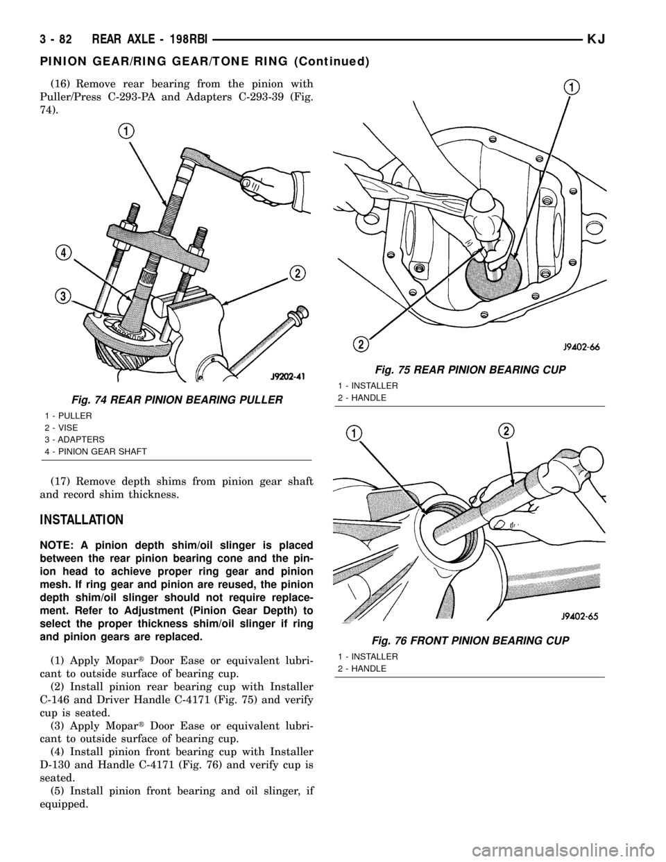
(16) Remove rear bearing from the pinion with
Puller/Press C-293-PA and Adapters C-293-39 (Fig.
74).
(17) Remove depth shims from pinion gear shaft
and record shim thickness.
INSTALLATION
NOTE: A pinion depth shim/oil slinger is placed
between the rear pinion bearing cone and the pin-
ion head to achieve proper ring gear and pinion
mesh. If ring gear and pinion are reused, the pinion
depth shim/oil slinger should not require replace-
ment. Refer to Adjustment (Pinion Gear Depth) to
select the proper thickness shim/oil slinger if ring
and pinion gears are replaced.
(1) Apply MopartDoor Ease or equivalent lubri-
cant to outside surface of bearing cup.
(2) Install pinion rear bearing cup with Installer
C-146 and Driver Handle C-4171 (Fig. 75) and verify
cup is seated.
(3) Apply MopartDoor Ease or equivalent lubri-
cant to outside surface of bearing cup.
(4) Install pinion front bearing cup with Installer
D-130 and Handle C-4171 (Fig. 76) and verify cup is
seated.
(5) Install pinion front bearing and oil slinger, if
equipped.
Fig. 74 REAR PINION BEARING PULLER
1 - PULLER
2 - VISE
3 - ADAPTERS
4 - PINION GEAR SHAFT
Fig. 75 REAR PINION BEARING CUP
1 - INSTALLER
2 - HANDLE
Fig. 76 FRONT PINION BEARING CUP
1 - INSTALLER
2 - HANDLE
3 - 82 REAR AXLE - 198RBIKJ
PINION GEAR/RING GEAR/TONE RING (Continued)
Page 132 of 1803
(6) Apply a light coating of gear lubricant on the
lip of pinion seal. Install seal with an appropriate
installer (Fig. 77).
(7) Install pinion depth shim on the pinion gear.
(8) Install rear bearing on the pinion gear with
Installer W-262 and a press (Fig. 78).
(9) Install anewcollapsible preload spacer on pin-
ion shaft and install pinion gear in the housing (Fig.
79).
(10) Install yoke with Installer C-3718 and Span-
ner Wrench 6958 (Fig. 80).
Fig. 77 PINION SEAL INSTALLER
1 - HANDLE
2 - INSTALLER
Fig. 78 REAR PINION BEARING
1 - PRESS
2 - INSTALLER
3 - PINION GEAR
4 - PINION GEAR REAR BEARING
Fig. 79 COLLAPSIBLE SPACER
1 - COLLAPSIBLE SPACER
2 - SHOULDER
3 - PINION GEAR
4 - PINION DEPTH SHIM
5 - REAR BEARING
Fig. 80 PINION YOKE INSTALLER
1 - INSTALLER
2 - PINION YOKE
3 - WRENCH
KJREAR AXLE - 198RBI 3 - 83
PINION GEAR/RING GEAR/TONE RING (Continued)
Page 133 of 1803

(11) Install the yoke washer and a new nut on the
pinion gear and tighten the pinion nut until there is
zero bearing end-play.
(12) Tighten the nut to 271 N´m (200 ft. lbs.).
CAUTION: Never loosen pinion gear nut to decrease
pinion gear bearing rotating torque and never
exceed specified preload torque. If preload torque
or rotating torque is exceeded a new collapsible
spacer must be installed.
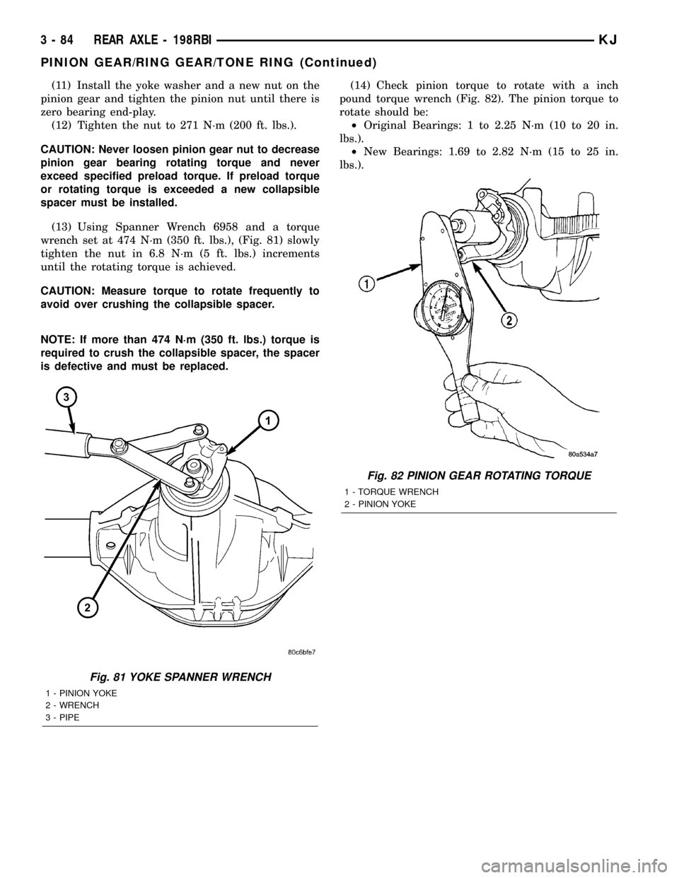
(13) Using Spanner Wrench 6958 and a torque
wrench set at 474 N´m (350 ft. lbs.), (Fig. 81) slowly
tighten the nut in 6.8 N´m (5 ft. lbs.) increments
until the rotating torque is achieved.
CAUTION: Measure torque to rotate frequently to
avoid over crushing the collapsible spacer.
NOTE: If more than 474 N´m (350 ft. lbs.) torque is
required to crush the collapsible spacer, the spacer
is defective and must be replaced.(14) Check pinion torque to rotate with a inch
pound torque wrench (Fig. 82). The pinion torque to
rotate should be:
²Original Bearings: 1 to 2.25 N´m (10 to 20 in.
lbs.).
²New Bearings: 1.69 to 2.82 N´m (15 to 25 in.
lbs.).
Fig. 81 YOKE SPANNER WRENCH
1 - PINION YOKE
2 - WRENCH
3 - PIPE
Fig. 82 PINION GEAR ROTATING TORQUE
1 - TORQUE WRENCH
2 - PINION YOKE
3 - 84 REAR AXLE - 198RBIKJ
PINION GEAR/RING GEAR/TONE RING (Continued)
Page 134 of 1803
(15) Invert the differential case and start two ring
gear bolts. This will provide case-to-ring gear bolt
hole alignment.
(16) Invert the differential case in the vise.
(17) Installnewring gear bolts and alternately
tighten to 129-142 N´m (95-105 ft. lbs.) (Fig. 83).
CAUTION: Do not reuse the bolts that held the ring
gear to the differential case. The bolts can fracture
causing extensive damage.
(18) Install differential in housing.
(19) Verify differential bearing preload, gear mesh
and contact pattern. Refer to Ajustments for proce-
dure.
(20) Install differential cover and fill with gear
lubricant.
(21) Install the propeller shaft with the reference
marks aligned.
(22) Remove supports and lower vehicle.
Fig. 83 RING GEAR
1 - TORQUE WRENCH
2 - RING GEAR BOLT
3 - RING GEAR
4 - CASE
KJREAR AXLE - 198RBI 3 - 85
PINION GEAR/RING GEAR/TONE RING (Continued)