2002 JEEP LIBERTY tone ring
[x] Cancel search: tone ringPage 1250 of 1803
NOTE: When refacing valves and valve seats, it is
important that the correct size valve guide pilot be
used for reseating stones. A true and complete sur-
face must be obtained.
(1) Using a suitable dial indicator measure the
center of the valve seat Total run out must not
exceed 0.051 mm (0.002 in).
(2) Apply a small amount of Prussian blue to the
valve seat, insert the valve into the cylinder head,
while applying light pressure on the valve rotate the
valve. Remove the valve and examine the valve face.
If the blue is transferred below the top edge of the
valve face, lower the valve seat using a 15 degree
stone. If the blue is transferred to the bottom edge of
the valve face, raise the valve seat using a 65 degree
stone.
(3) When the seat is properly positioned the width
of the intake seat must be 1.75 ± 2.36 mm (0.0689 ±
0.0928 in.) and the exhaust seat must be 1.71 ± 2.32
mm (0.0673 ± 0.0911 in.).
(4) Check the valve spring installed height after
refacing the valve and seat. The installed height for
both intake and exhaust valve springs must not
exceed 41.44 mm (1.6315 in.).
(5) The valve seat and valve face must maintain a
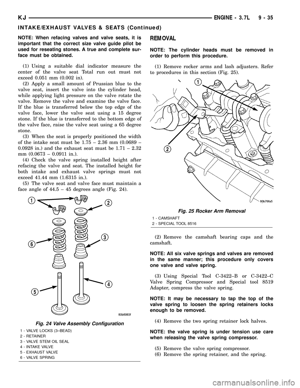
face angle of 44.5 ± 45 degrees angle (Fig. 24).REMOVAL
NOTE: The cylinder heads must be removed in
order to perform this procedure.
(1) Remove rocker arms and lash adjusters. Refer
to procedures in this section (Fig. 25).
(2) Remove the camshaft bearing caps and the
camshaft.
NOTE: All six valve springs and valves are removed
in the same manner; this procedure only covers
one valve and valve spring.
(3) Using Special Tool C-3422±B or C-3422±C
Valve Spring Compressor and Special tool 8519
Adapter, compress the valve spring.
NOTE: It may be necessary to tap the top of the
valve spring to loosen the spring retainers locks
enough to be removed.
(4) Remove the two spring retainer lock halves.
NOTE: the valve spring is under tension use care
when releasing the valve spring compressor.
(5) Remove the valve spring compressor.
(6) Remove the spring retainer, and the spring.
Fig. 24 Valve Assembly Configuration
1 - VALVE LOCKS (3±BEAD)
2 - RETAINER
3 - VALVE STEM OIL SEAL
4 - INTAKE VALVE
5 - EXHAUST VALVE
6 - VALVE SPRING
Fig. 25 Rocker Arm Removal
1 - CAMSHAFT
2 - SPECIAL TOOL 8516
KJENGINE - 3.7L 9 - 35
INTAKE/EXHAUST VALVES & SEATS (Continued)
Page 1251 of 1803
NOTE: Check for sharp edges on the keeper
grooves. Remove any burrs from the valve stem
before removing the valve from the cylinder head.
(7) Remove the valve from the cylinder head.
NOTE: The valve stem seals are common between
intake and exhaust.
(8) Remove the valve stem seal. Mark the valve for
proper installation.
TESTING VALVE SPRINGS
NOTE: Whenever the valves are removed from the
cylinder head it is recommended that the valve
springs be inspected and tested for reuse.
Inspect the valve springs for physical signs of wear
or damage. Turn table of tool C-647 until surface is
in line with the 40.69 mm (1.602 in.) mark on the
threaded stud and the zero mark on the front. Place
spring over the stud on the table and lift compress-
ing lever to set tone device. Pull on torque wrench
until Ping is heard. Take reading on torque wrench
at this instant. Multiply this reading by two. This
will give the spring load at test length. Fractional
measurements are indicated on the table for finer
adjustments. Refer to Specifications Section to obtain
specified height and allowable tensions. Replace any
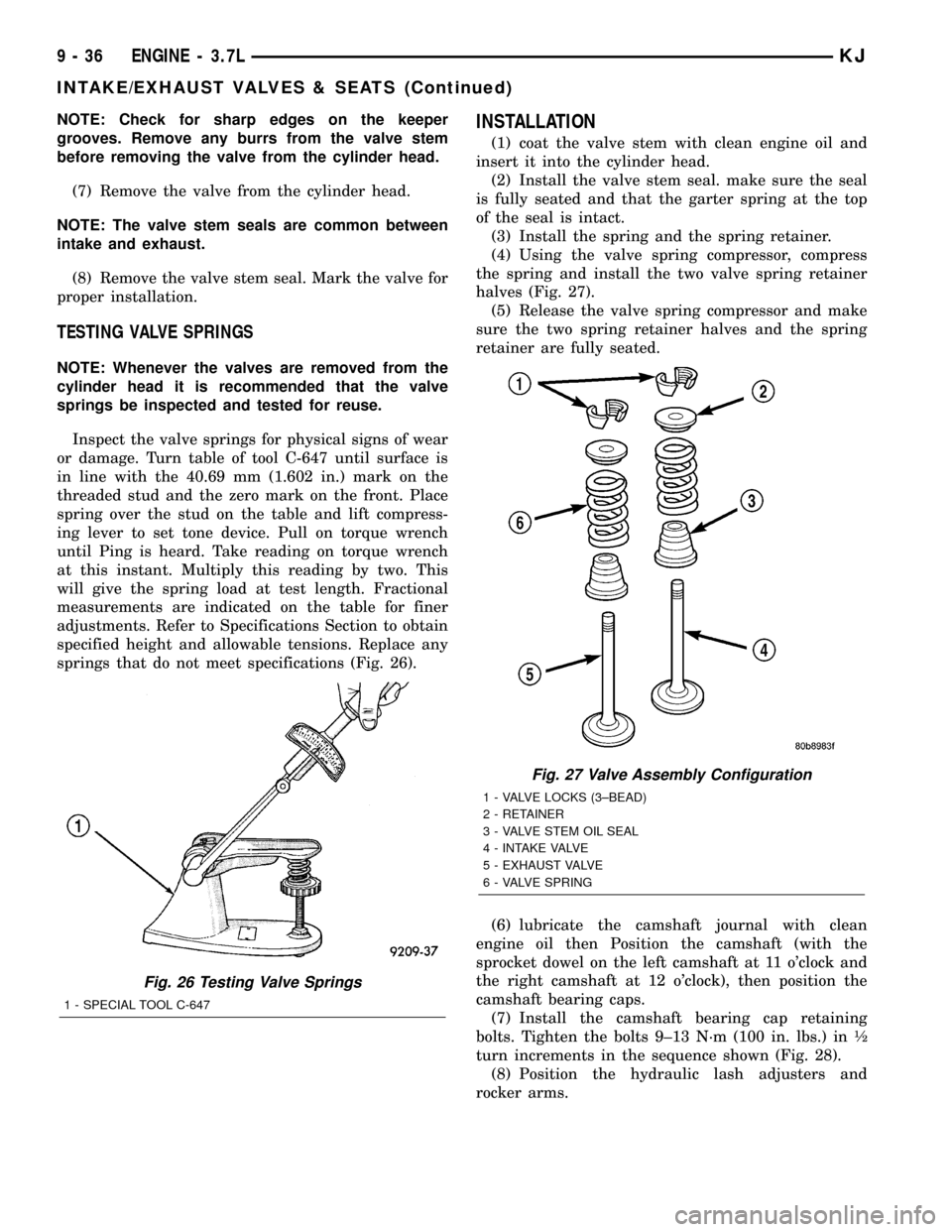
springs that do not meet specifications (Fig. 26).
INSTALLATION
(1) coat the valve stem with clean engine oil and
insert it into the cylinder head.
(2) Install the valve stem seal. make sure the seal
is fully seated and that the garter spring at the top
of the seal is intact.
(3) Install the spring and the spring retainer.
(4) Using the valve spring compressor, compress
the spring and install the two valve spring retainer
halves (Fig. 27).
(5) Release the valve spring compressor and make
sure the two spring retainer halves and the spring
retainer are fully seated.
(6) lubricate the camshaft journal with clean
engine oil then Position the camshaft (with the
sprocket dowel on the left camshaft at 11 o'clock and
the right camshaft at 12 o'clock), then position the
camshaft bearing caps.
(7) Install the camshaft bearing cap retaining
bolts. Tighten the bolts 9±13 N´m (100 in. lbs.) in ó
turn increments in the sequence shown (Fig. 28).
(8) Position the hydraulic lash adjusters and
rocker arms.
Fig. 26 Testing Valve Springs
1 - SPECIAL TOOL C-647
Fig. 27 Valve Assembly Configuration
1 - VALVE LOCKS (3±BEAD)
2 - RETAINER
3 - VALVE STEM OIL SEAL
4 - INTAKE VALVE
5 - EXHAUST VALVE
6 - VALVE SPRING
9 - 36 ENGINE - 3.7LKJ
INTAKE/EXHAUST VALVES & SEATS (Continued)
Page 1254 of 1803
ENGINE BLOCK
DESCRIPTION
The cylinder block is made of cast iron. The block
is a closed deck design with the left bank forward. To
provide high rigidity and improved NVH an
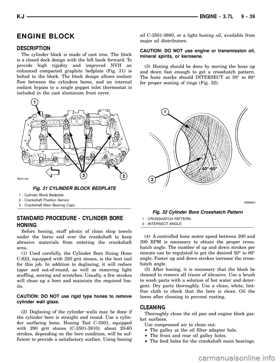
enhanced compacted graphite bedplate (Fig. 31) is
bolted to the block. The block design allows coolant
flow between the cylinders bores, and an internal
coolant bypass to a single poppet inlet thermostat is
included in the cast aluminum front cover.
STANDARD PROCEDURE - CYLINDER BORE
HONING
Before honing, stuff plenty of clean shop towels
under the bores and over the crankshaft to keep
abrasive materials from entering the crankshaft
area.
(1) Used carefully, the Cylinder Bore Sizing Hone
C-823, equipped with 220 grit stones, is the best tool
for this job. In addition to deglazing, it will reduce
taper and out-of-round, as well as removing light
scuffing, scoring and scratches. Usually, a few strokes
will clean up a bore and maintain the required lim-
its.
CAUTION: DO NOT use rigid type hones to remove
cylinder wall glaze.
(2) Deglazing of the cylinder walls may be done if
the cylinder bore is straight and round. Use a cylin-
der surfacing hone, Honing Tool C-3501, equipped
with 280 grit stones (C-3501-3810). about 20-60
strokes, depending on the bore condition, will be suf-
ficient to provide a satisfactory surface. Using honingoil C-3501-3880, or a light honing oil, available from
major oil distributors.
CAUTION: DO NOT use engine or transmission oil,
mineral spirits, or kerosene.
(3) Honing should be done by moving the hone up
and down fast enough to get a crosshatch pattern.
The hone marks should INTERSECT at 50É to 60É
for proper seating of rings (Fig. 32).
(4) A controlled hone motor speed between 200 and
300 RPM is necessary to obtain the proper cross-
hatch angle. The number of up and down strokes per
minute can be regulated to get the desired 50É to 60É
angle. Faster up and down strokes increase the cross-
hatch angle.
(5) After honing, it is necessary that the block be
cleaned to remove all traces of abrasive. Use a brush
to wash parts with a solution of hot water and deter-
gent. Dry parts thoroughly. Use a clean, white, lint-
free cloth to check that the bore is clean. Oil the
bores after cleaning to prevent rusting.
CLEANING
Thoroughly clean the oil pan and engine block gas-
ket surfaces.
Use compressed air to clean out:
²The galley at the oil filter adaptor hole.
²The front and rear oil galley holes.
²The feed holes for the crankshaft main bearings.
Fig. 31 CYLINDER BLOCK BEDPLATE
1 - Cylinder Block Bedplate
2 - Crankshaft Position Sensor
3 - Crankshaft Main Bearing Caps
Fig. 32 Cylinder Bore Crosshatch Pattern
1 - CROSSHATCH PATTERN
2 - INTERSECT ANGLE
KJENGINE - 3.7L 9 - 39
Page 1258 of 1803
REMOVAL
NOTE: To remove the crankshaft from the engine,
the engine must be removed from the vehicle.
(1) Remove the engine. Refer to Engine Assembly
in this section for procedure.
(2) Remove the engine oil pump. Refer to Oil
Pump in this section for procedure.
CAUTION: DO NOT pry on the oil pan gasket when
removing the oil pan, The oil pan gasket is mounted
to the cylinder block in three locations and will
remain attached to block when removing oil pan.
Gasket can not be removed with oil pan.
(3) Remove oil pan bolts and oil pan.
(4) Remove the oil pump pickup tube and oil pan
gasket /windage tray.
(5) Remove the bedplate mounting bolts. Note the
location of the two stud bolts for installation.
(6) Remove the connecting rods from the crank-
shaft.
CAUTION: The bedplate to cylinder block mating
surface is a critical sealing surface. Do not pry on
or damage this surface in anyway.
NOTE: The bedplate contains the lower main bear-
ing halves. Use care when handling bedplate as not
to drop or damage bearing halves. Installing main
bearing halves in the wrong position will cause
sever damage to the crankshaft.
NOTE: The bedplate has pry points cast into it. Use
these points only. The pry points are shown below.
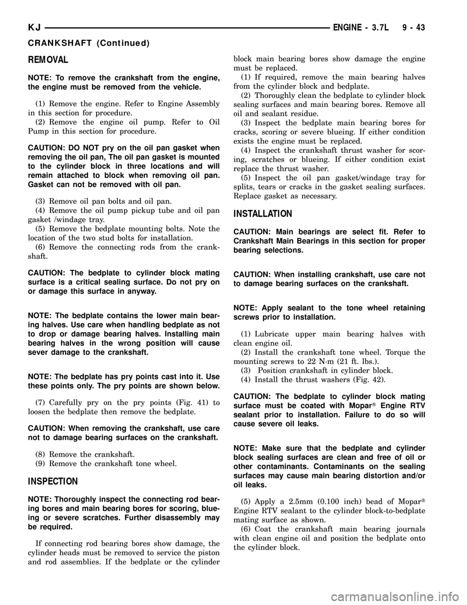
(7) Carefully pry on the pry points (Fig. 41) to
loosen the bedplate then remove the bedplate.
CAUTION: When removing the crankshaft, use care
not to damage bearing surfaces on the crankshaft.
(8) Remove the crankshaft.
(9) Remove the crankshaft tone wheel.
INSPECTION
NOTE: Thoroughly inspect the connecting rod bear-
ing bores and main bearing bores for scoring, blue-
ing or severe scratches. Further disassembly may
be required.
If connecting rod bearing bores show damage, the
cylinder heads must be removed to service the piston
and rod assemblies. If the bedplate or the cylinderblock main bearing bores show damage the engine
must be replaced.
(1) If required, remove the main bearing halves
from the cylinder block and bedplate.
(2) Thoroughly clean the bedplate to cylinder block
sealing surfaces and main bearing bores. Remove all
oil and sealant residue.
(3) Inspect the bedplate main bearing bores for
cracks, scoring or severe blueing. If either condition
exists the engine must be replaced.
(4) Inspect the crankshaft thrust washer for scor-
ing, scratches or blueing. If either condition exist
replace the thrust washer.
(5) Inspect the oil pan gasket/windage tray for
splits, tears or cracks in the gasket sealing surfaces.
Replace gasket as necessary.
INSTALLATION
CAUTION: Main bearings are select fit. Refer to
Crankshaft Main Bearings in this section for proper
bearing selections.
CAUTION: When installing crankshaft, use care not
to damage bearing surfaces on the crankshaft.
NOTE: Apply sealant to the tone wheel retaining
screws prior to installation.
(1) Lubricate upper main bearing halves with
clean engine oil.
(2) Install the crankshaft tone wheel. Torque the
mounting screws to 22 N´m (21 ft. lbs.).
(3) Position crankshaft in cylinder block.
(4) Install the thrust washers (Fig. 42).
CAUTION: The bedplate to cylinder block mating
surface must be coated with MoparTEngine RTV
sealant prior to installation. Failure to do so will
cause severe oil leaks.
NOTE: Make sure that the bedplate and cylinder
block sealing surfaces are clean and free of oil or
other contaminants. Contaminants on the sealing
surfaces may cause main bearing distortion and/or
oil leaks.
(5) Apply a 2.5mm (0.100 inch) bead of Mopart
Engine RTV sealant to the cylinder block-to-bedplate
mating surface as shown.
(6) Coat the crankshaft main bearing journals
with clean engine oil and position the bedplate onto
the cylinder block.
KJENGINE - 3.7L 9 - 43
CRANKSHAFT (Continued)
Page 1328 of 1803
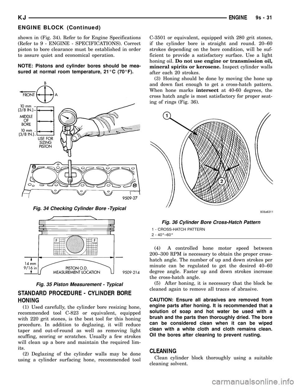
shown in (Fig. 34). Refer to for Engine Specifications
(Refer to 9 - ENGINE - SPECIFICATIONS). Correct
piston to bore clearance must be established in order
to assure quiet and economical operation.
NOTE: Pistons and cylinder bores should be mea-
sured at normal room temperature, 21ÉC (70ÉF).
STANDARD PROCEDURE - CYLINDER BORE
HONING
(1) Used carefully, the cylinder bore resizing hone,
recommended tool C-823 or equivalent, equipped
with 220 grit stones, is the best tool for this honing
procedure. In addition to deglazing, it will reduce
taper and out-of-round as well as removing light
scuffing, scoring or scratches. Usually a few strokes
will clean up a bore and maintain the required lim-
its.
(2) Deglazing of the cylinder walls may be done
using a cylinder surfacing hone, recommended toolC-3501 or equivalent, equipped with 280 grit stones,
if the cylinder bore is straight and round. 20±60
strokes depending on the bore condition, will be suf-
ficient to provide a satisfactory surface. Use a light
honing oil.Do not use engine or transmission oil,
mineral spirits or kerosene.Inspect cylinder walls
after each 20 strokes.
(3) Honing should be done by moving the hone up
and down fast enough to get a cross-hatch pattern.
When hone marksintersectat 40-60 degrees, the
cross hatch angle is most satisfactory for proper seat-
ing of rings (Fig. 36).
(4) A controlled hone motor speed between
200±300 RPM is necessary to obtain the proper cross-
hatch angle. The number of up and down strokes per
minute can be regulated to get the desired 40±60
degree angle. Faster up and down strokes increase
the cross-hatch angle.
(5) After honing, it is necessary that the block be
cleaned again to remove all traces of abrasive.
CAUTION: Ensure all abrasives are removed from
engine parts after honing. It is recommended that a
solution of soap and hot water be used with a
brush and the parts then thoroughly dried. The bore
can be considered clean when it can be wiped
clean with a white cloth and cloth remains clean.
Oil the bores after cleaning to prevent rusting.
CLEANING
Clean cylinder block thoroughly using a suitable
cleaning solvent.
Fig. 34 Checking Cylinder Bore -Typical
Fig. 35 Piston Measurement - Typical
Fig. 36 Cylinder Bore Cross-Hatch Pattern
1 - CROSS-HATCH PATTERN
2 - 40ɱ60É
KJENGINE9s-31
ENGINE BLOCK (Continued)
Page 1413 of 1803
OPERATION
2.4L
Engine speed and crankshaft position are provided
through the CKP (Crankshaft Position) sensor. The
sensor generates pulses that are the input sent to the
Powertrain Control Module (PCM). The PCM inter-
prets the sensor input to determine the crankshaft
position. The PCM then uses this position, along with
other inputs, to determine injector sequence and igni-
tion timing.
The sensor is a hall effect device combined with an
internal magnet. It is also sensitive to steel within a
certain distance from it.
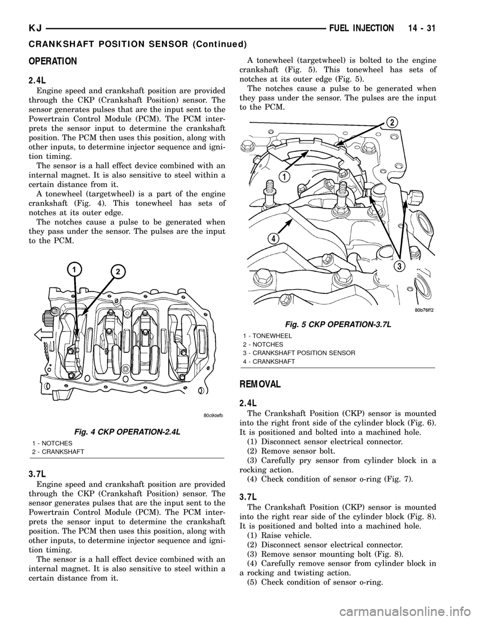
A tonewheel (targetwheel) is a part of the engine
crankshaft (Fig. 4). This tonewheel has sets of
notches at its outer edge.
The notches cause a pulse to be generated when
they pass under the sensor. The pulses are the input
to the PCM.
3.7L
Engine speed and crankshaft position are provided
through the CKP (Crankshaft Position) sensor. The
sensor generates pulses that are the input sent to the
Powertrain Control Module (PCM). The PCM inter-
prets the sensor input to determine the crankshaft
position. The PCM then uses this position, along with
other inputs, to determine injector sequence and igni-
tion timing.
The sensor is a hall effect device combined with an
internal magnet. It is also sensitive to steel within a
certain distance from it.A tonewheel (targetwheel) is bolted to the engine
crankshaft (Fig. 5). This tonewheel has sets of
notches at its outer edge (Fig. 5).
The notches cause a pulse to be generated when
they pass under the sensor. The pulses are the input
to the PCM.
REMOVAL
2.4L
The Crankshaft Position (CKP) sensor is mounted
into the right front side of the cylinder block (Fig. 6).
It is positioned and bolted into a machined hole.
(1) Disconnect sensor electrical connector.
(2) Remove sensor bolt.
(3) Carefully pry sensor from cylinder block in a
rocking action.
(4) Check condition of sensor o-ring (Fig. 7).
3.7L
The Crankshaft Position (CKP) sensor is mounted
into the right rear side of the cylinder block (Fig. 8).
It is positioned and bolted into a machined hole.
(1) Raise vehicle.
(2) Disconnect sensor electrical connector.
(3) Remove sensor mounting bolt (Fig. 8).
(4) Carefully remove sensor from cylinder block in
a rocking and twisting action.
(5) Check condition of sensor o-ring.
Fig. 4 CKP OPERATION-2.4L
1 - NOTCHES
2 - CRANKSHAFT
Fig. 5 CKP OPERATION-3.7L
1 - TONEWHEEL
2 - NOTCHES
3 - CRANKSHAFT POSITION SENSOR
4 - CRANKSHAFT
KJFUEL INJECTION 14 - 31
CRANKSHAFT POSITION SENSOR (Continued)
Page 1750 of 1803
FUEL PRESSURE REGULATOR -
DESCRIPTION.......................14-13
FUEL PRESSURE REGULATOR -
INSTALLATION.......................14-14
FUEL PRESSURE REGULATOR -
OPERATION.........................14-14
FUEL PRESSURE REGULATOR -
REMOVAL..........................14-14
FUEL PUMP - DESCRIPTION............14-15
FUEL PUMP - OPERATION.............14-15
FUEL PUMP AMPERAGE TEST -
DIAGNOSIS AND TESTING.............14-16
FUEL PUMP CAPACITY TEST -
DIAGNOSIS AND TESTING.............14-15
FUEL PUMP MODULE - DESCRIPTION....14-18
FUEL PUMP MODULE - INSTALLATION . . . 14-19
FUEL PUMP MODULE - OPERATION......14-18
FUEL PUMP MODULE - REMOVAL.......14-18
FUEL PUMP PRESSURE TEST -
DIAGNOSIS AND TESTING.............14-15
FUEL PUMP RELAY - DESCRIPTION......14-34
FUEL PUMP RELAY - DIAGNOSIS AND
TESTING...........................14-34
FUEL PUMP RELAY - INSTALLATION.....14-34
FUEL PUMP RELAY - OPERATION........14-34
FUEL PUMP RELAY - REMOVAL.........14-34
FUEL PUMP RELAYS - DIAGNOSIS AND
TESTING, ASD........................8I-4
FUEL RAIL - DESCRIPTION.............14-21
FUEL RAIL - INSTALLATION..............14-24
FUEL RAIL - OPERATION...............14-21
FUEL RAIL - REMOVAL................14-22
FUEL SYSTEM PRESSURE RELEASE -
STANDARD PROCEDURE................14-4
FUEL SYSTEM PRESSURE,
SPECIFICATIONS......................14-5
FUEL SYSTEM, SPECIAL TOOLS..........14-6
FUEL TANK - DESCRIPTION............14-24
FUEL TANK - INSTALLATION............14-27
FUEL TANK - OPERATION..............14-24
FUEL TANK - REMOVAL...............14-25
FUEL TANK CHECK VALVE -
DESCRIPTION.......................14-28
FUEL TANK CHECK VALVE -
INSTALLATION.......................14-28
FUEL TANK CHECK VALVE - OPERATION . . 14-28
FUEL TANK CHECK VALVE - REMOVAL....14-28
FUEL TANK SKID PLATE - INSTALLATION . . . 13-9
FUEL TANK SKID PLATE - REMOVAL......13-9
FULL TIME INDICATOR - DESCRIPTION . . . 8J-29
FULL TIME INDICATOR - OPERATION.....8J-30
FUNCTION - DIAGNOSIS AND TESTING,
REAR HVAC CONTROL ASSEMBLY
WINDOW DEFOGGER..................8G-9
FUNCTIONS - DESCRIPTION, CIRCUIT . . 8W-01-6
FUSE - DESCRIPTION, IOD...........8W-97-3
FUSE - INSTALLATION, IOD..........8W-97-3
FUSE - OPERATION, IOD.............8W-97-3
FUSE - REMOVAL, IOD..............8W-97-3
FUSES POWERING SEVERAL LOADS -
STANDARD PROCEDURE, TESTING
FOR A SHORT TO GROUND ON.......8W-01-9
GALLERY PLUGS - STANDARD
PROCEDURE, ENGINE CORE AND OIL.....9-10
GAP AND FLUSH - SPECIFICATIONS.....23-116
GAS ENGINES - GENERATOR RATINGS....8F-23
GAS POWERED - STARTER MOTOR......8F-39
GAS POWERED - TORQUE
.............8F-38
GASKET - DIAGNOSIS AND TESTING,
CYLINDER HEAD
..................9-19,9-30
GASKET SURFACE PREPARATION -
STANDARD PROCEDURE, ENGINE
.........9-9
GATE - INSTALLATION, SWING
.........23-138
GATE - REMOVAL, SWING
............23-138
GATE AJAR INDICATOR - DESCRIPTION
. . . 8J-20
GATE AJAR INDICATOR - OPERATION
.....8J-20
GATE BELTLINE WEATHERSTRIP -
INSTALLATION, SWING
...............23-186
GATE BELTLINE WEATHERSTRIP -
REMOVAL, SWING
...................23-186
GATE OPENING WEATHERSTRIP -
INSTALLATION, SWING
...............23-186
GATE OPENING WEATHERSTRIP -
REMOVAL, SWING
...................23-186
GAUGE - DESCRIPTION, ENGINE
TEMPERATURE
......................8J-18
GAUGE - DESCRIPTION, FUEL
...........8J-19GAUGE - OPERATION, ENGINE
TEMPERATURE......................8J-18
GAUGE - OPERATION, FUEL............8J-20
GEAR - DESCRIPTION.................19-13
GEAR - INSTALLATION, PINION
GEAR/RING..........................3-46
GEAR - OPERATION...................19-13
GEAR - REMOVAL, PINION GEAR/RING....3-44
GEAR/RING GEAR - INSTALLATION,
PINION.............................3-46
GEAR/RING GEAR - REMOVAL, PINION....3-44
GEAR/RING GEAR/TONE RING -
INSTALLATION, PINION............3-112,3-82
GEAR/RING GEAR/TONE RING -
REMOVAL, PINION...............3-110,3-79
GEARSHIFT CABLE - ADJUSTMENTS....21-130
GEARSHIFT CABLE - DIAGNOSIS AND
TESTING..........................21-128
GEARSHIFT CABLE - INSTALLATION.....21-129
GEARSHIFT CABLE - REMOVAL........21-128
GEAR/TONE RING - INSTALLATION,
PINION GEAR/RING...............3-112,3-82
GEAR/TONE RING - REMOVAL, PINION
GEAR/RING.....................3-110,3-79
GEARTRAIN - ASSEMBLY, PLANETARY . . . 21-160
GEARTRAIN - CLEANING, PLANETARY . . . 21-159
GEARTRAIN - DESCRIPTION,
PLANETARY........................21-157
GEARTRAIN - DISASSEMBLY,
PLANETARY........................21-159
GEARTRAIN - INSPECTION, PLANETARY . 21-159
GEARTRAIN - OPERATION, PLANETARY . . 21-157
GENERAL - WARNINGS.............8W-01-7
GENERATOR - DESCRIPTION...........8F-25
GENERATOR - INSTALLATION...........8F-26
GENERATOR - OPERATION.............8F-25
GENERATOR - REMOVAL...............8F-25
GENERATOR DECOUPLER - DIAGNOSIS
AND TESTING.......................8F-27
GENERATOR DECOUPLER PULLEY -
DESCRIPTION.......................8F-26
GENERATOR DECOUPLER PULLEY -
INSTALLATION.......................8F-30
GENERATOR DECOUPLER PULLEY -
OPERATION.........................8F-27
GENERATOR DECOUPLER PULLEY -
REMOVAL..........................8F-27
GENERATOR RATINGS, GAS ENGINES....8F-23
GLASS - INSTALLATION, DOOR . . 23-122,23-129,
23-172
GLASS - INSTALLATION, FLIP-UP.......23-136
GLASS - REMOVAL, DOOR......23-122,23-129,
23-172
GLASS - REMOVAL, FLIP-UP..........23-136
GLASS AJAR INDICATOR - DESCRIPTION . . 8J-21
GLASS AJAR INDICATOR - OPERATION . . . 8J-21
GLASS AJAR SWITCH - DESCRIPTION,
FLIP-UP............................8L-77
GLASS AJAR SWITCH - OPERATION,
FLIP-UP............................8L-77
GLASS HEATING GRID REPAIR -
STANDARD PROCEDURE, REAR..........8G-4
GLASS LATCH - INSTALLATION, FLIP-UP . 23-136
GLASS LATCH - REMOVAL, FLIP-UP.....23-136
GLASS PANEL - INSTALLATION........23-178
GLASS PANEL - REMOVAL............23-178
GLASS PANEL ADJUSTMENT,
ADJUSTMENTS - SUNROOF...........23-178
GLASS PANEL SEAL - INSTALLATION
....23-178
GLASS PANEL SEAL - REMOVAL
.......23-178
GLASS RELEASE SWITCH - DIAGNOSIS
AND TESTING, FLIP-UP
................8N-5
GLASS RUN CHANNEL - INSTALLATION
. 23-123,
23-130
GLASS RUN CHANNEL - REMOVAL
.....23-123,
23-130
GLASS SUPPORT CYLINDER -
INSTALLATION, FLIP-UP
..............23-139
GLASS SUPPORT CYLINDER -
REMOVAL, FLIP-UP
..................23-139
GLOVE BOX - INSTALLATION
..........23-148
GLOVE BOX - REMOVAL
..............23-148
GLOVE BOX LATCH - INSTALLATION
....23-148
GLOVE BOX LATCH - REMOVAL
........23-148
GLOVE BOX LATCH STRIKER -
INSTALLATION
......................23-149
GLOVE BOX LATCH STRIKER - REMOVAL
. 23-148GRAB HANDLE - INSTALLATION,
A-PILLAR TRIM.....................23-156
GRAB HANDLE - REMOVAL, A-PILLAR
TRIM.............................23-156
GRID - DESCRIPTION, REAR WINDOW
DEFOGGER..........................8G-5
GRID - DIAGNOSIS AND TESTING, REAR
WINDOW DEFOGGER..................8G-5
GRID - OPERATION, REAR WINDOW
DEFOGGER..........................8G-5
GRID REPAIR - STANDARD PROCEDURE,
REAR GLASS HEATING.................8G-4
GRILLE - INSTALLATION..............23-142
GRILLE - INSTALLATION, COWL........23-140
GRILLE - REMOVAL..................23-142
GRILLE - REMOVAL, COWL...........23-140
GRILLE OPENING REINFORCEMENT -
INSTALLATION......................23-142
GRILLE OPENING REINFORCEMENT -
REMOVAL.........................23-142
GROUND - STANDARD PROCEDURE,
TESTING FOR A SHORT TO..........8W-01-9
GROUND AND SPLICE INFORMATION -
DESCRIPTION, CONNECTOR..........8W-01-7
GROUND ON FUSES POWERING
SEVERAL LOADS - STANDARD
PROCEDURE, TESTING FOR A SHORT
TO..............................8W-01-9
GROUND STRAP - DESCRIPTION, RADIO
NOISE SUPPRESSION..................8A-9
GROUND STRAP - INSTALLATION,
RADIO NOISE SUPPRESSION...........8A-11
GROUND STRAP - OPERATION, RADIO
NOISE SUPPRESSION.................8A-10
GROUND STRAP - REMOVAL, RADIO
NOISE SUPPRESSION.................8A-10
GROUNDS - DESCRIPTION, POWER......8E-13
GUARD - DESCRIPTION, THERMAL......8F-20
GUARD - INSTALLATION, THERMAL......8F-20
GUARD - OPERATION, THERMAL........8F-20
GUARD - REMOVAL, THERMAL..........8F-20
GUIDE ASSEMBLY - INSTALLATION.....23-179
GUIDE ASSEMBLY - REMOVAL.........23-179
GUIDE SEALS - DESCRIPTION, VALVE . 9-29,9-38
GUIDES - DESCRIPTION, VALVE......9-19,9-30
HALF SHAFT - CAUTION................3-10
HALF SHAFT - DIAGNOSIS AND TESTING . . 3-10
HALF SHAFT - INSTALLATION............3-11
HALF SHAFT - REMOVAL...............3-10
HALF SHAFT, SPECIFICATIONS...........3-11
HANDLE - INSTALLATION, A-PILLAR
TRIM AND GRAB....................23-156
HANDLE - INSTALLATION, ASSIST......23-157
HANDLE - INSTALLATION, EXTERIOR . . . 23-123,
23-130,23-136
HANDLE - INSTALLATION, LATCH
RELEASE..........................23-120
HANDLE - REMOVAL, A-PILLAR TRIM
AND GRAB.........................23-156
HANDLE - REMOVAL, ASSIST..........23-157
HANDLE - REMOVAL, EXTERIOR . 23-123,23-130,
23-136
HANDLE - REMOVAL, LATCH RELEASE . . 23-120
HANDLING NON-DEPLOYED
SUPPLEMENTAL RESTRAINTS -
STANDARD PROCEDURE...............8O-6
HARNESS - DIAGNOSIS AND TESTING,
WIRING
..........................8W-01-7
HAZARD SWITCH - DESCRIPTION
.......8L-29
HAZARD SWITCH - INSTALLATION
.......8L-30
HAZARD SWITCH - OPERATION
.........8L-29
HAZARD SWITCH - REMOVAL
..........8L-30
HCU (HYDRAULIC CONTROL UNIT) -
DESCRIPTION
........................5-35
HCU (HYDRAULIC CONTROL UNIT) -
INSTALLATION
........................5-36
HCU (HYDRAULIC CONTROL UNIT) -
OPERATION
..........................5-35
HCU (HYDRAULIC CONTROL UNIT) -
REMOVAL
...........................5-36
HEAD - DESCRIPTION, CYLINDER
........9-30
HEAD COVER(S) - DESCRIPTION,
CYLINDER
...........................9-25
HEAD COVER(S) - INSTALLATION,
CYLINDER
.......................9-26,9-34
HEAD COVER(S) - REMOVAL, CYLINDER
. . 9-25,
9-34
KJINDEX 11
Description Group-Page Description Group-Page Description Group-Page
Page 1757 of 1803
OPERATION - DESCRIPTION, MODES OF . . 8E-11
OPERATION - DIAGNOSIS AND TESTING,
AIR CHECKING TRANSMISSION
CLUTCH............................21-80
ORDER, 2.4L 4-CYLINDER - ENGINE
FIRING..............................8I-2
ORDER, 3.7L V-6 - ENGINE FIRING........8I-2
ORIFICE TUBE - DESCRIPTION, A/C......24-50
ORIFICE TUBE - INSTALLATION, A/C......24-50
ORIFICE TUBE - OPERATION, A/C........24-50
ORIFICE TUBE - REMOVAL, A/C.........24-50
ORVR - DESCRIPTION.................25-29
ORVR - OPERATION..................25-29
OUT - ADJUSTMENT, LOCK..............5-30
OUTBOARD SEAT BELT & RETRACTOR -
INSTALLATION, REAR.................8O-34
OUTBOARD SEAT BELT & RETRACTOR -
REMOVAL, REAR....................8O-33
OUTER BELT MOLDING - INSTALLATION,
FRONT DOOR......................23-186
OUTER BELT MOLDING - INSTALLATION,
REAR DOOR.......................23-186
OUTER BELT MOLDING - REMOVAL,
FRONT DOOR......................23-186
OUTER BELT MOLDING - REMOVAL,
REAR DOOR.......................23-186
OUTER TIE ROD END REMOVAL TOOL,
SPECIAL TOOLS.....................19-15
OUTLET - DESCRIPTION, CIGAR
LIGHTER.........................8W-97-2
OUTLET - DESCRIPTION, POWER......8W-97-11
OUTLET - DIAGNOSIS AND TESTING,
CIGAR LIGHTER...................8W-97-2
OUTLET - DIAGNOSIS AND TESTING,
POWER.........................8W-97-11
OUTLET - INSTALLATION, POWER....8W-97-13
OUTLET - OPERATION, CIGAR LIGHTER . 8W-97-2
OUTLET - OPERATION, POWER......8W-97-11
OUTLET - REMOVAL, POWER........8W-97-12
OUTLET BARRELS - INSTALLATION,
PANEL.............................24-29
OUTLET BARRELS - REMOVAL, PANEL . . . 24-29
OUTLETS - DESCRIPTION, DEMISTER....24-29
OUTPUT - DESCRIPTION, PCM...........8I-4
OUTPUT - OPERATION, PCM............14-33
OUTPUT - OPERATION, PCM.............8I-4
OUTPUT SHAFT SEAL - INSTALLATION,
FRONT......................21-208,21-246
OUTPUT SHAFT SEAL - INSTALLATION,
REAR.............................21-212
OUTPUT SHAFT SEAL - REMOVAL,
FRONT......................21-208,21-246
OUTPUT SHAFT SEAL - REMOVAL, REAR . 21-210
OUTPUT SPEED SENSOR - DESCRIPTION . 21-152
OUTPUT SPEED SENSOR -
INSTALLATION......................21-152
OUTPUT SPEED SENSOR - OPERATION . . 21-152
OUTPUT SPEED SENSOR - REMOVAL . . . 21-152
OVERDRIVE OFF INDICATOR -
DESCRIPTION.......................8J-26
OVERDRIVE OFF INDICATOR -
OPERATION.........................8J-26
OVERDRIVE SWITCH - DESCRIPTION....21-153
OVERDRIVE SWITCH - OPERATION.....21-153
OVERHEAD CONSOLE - DESCRIPTION....8M-1
OVERHEAD CONSOLE - OPERATION......8M-2
OVERHEAD CONSOLE, REMOVAL........8M-4
OVERRIDE RELAY - DESCRIPTION,
CLUTCH SWITCH......................6-10
OVERRIDE RELAY - INSTALLATION,
CLUTCH SWITCH......................6-10
OVERRIDE RELAY - OPERATION,
CLUTCH SWITCH......................6-10
OVERRIDE RELAY - REMOVAL, CLUTCH
SWITCH.............................6-10
OXYGEN SENSOR - DESCRIPTION.......14-40
OXYGEN SENSOR - INSTALLATION.......14-43
OXYGEN SENSOR - OPERATION.........14-40
OXYGEN SENSOR - REMOVAL..........14-41
PADS - INSTALLATION, FRONT BRAKE.....5-11
PADS - REMOVAL, FRONT BRAKE........5-11
PAINT CODE - DESCRIPTION..........23-162
PAINT CODES - SPECIFICATIONS.......23-162
PAINT TOUCH-UP - DESCRIPTION
......23-163
PAN - CLEANING, OIL
..................9-63
PAN - DESCRIPTION, OIL
...............9-63
PAN - INSPECTION, OIL
................9-63
PAN - INSTALLATION, OIL
...............9-64PAN - REMOVAL, OIL..................9-63
PANEL - DESCRIPTION, LATCH - ACCESS . 23-139
PANEL - INSTALLATION, GLASS........23-178
PANEL - INSTALLATION, LATCH -
ACCESS...........................23-139
PANEL - INSTALLATION, QUARTER TRIM . 23-159
PANEL - INSTALLATION, TRIM . . . 23-126,23-132,
23-138
PANEL - REMOVAL, GLASS............23-178
PANEL - REMOVAL, LATCH - ACCESS . . . 23-139
PANEL - REMOVAL, QUARTER TRIM....23-159
PANEL - REMOVAL, TRIM . 23-125,23-132,23-138
PANEL ADJUSTMENT, ADJUSTMENTS -
SUNROOF GLASS...................23-178
PANEL ANTENNA CABLE -
INSTALLATION, INSTRUMENT............8A-8
PANEL ANTENNA CABLE - REMOVAL,
INSTRUMENT........................8A-7
PANEL ASSEMBLY - INSTALLATION,
INSTRUMENT......................23-151
PANEL ASSEMBLY - REMOVAL,
INSTRUMENT......................23-149
PANEL CENTER BEZEL - INSTALLATION,
INSTRUMENT......................23-154
PANEL CENTER BEZEL - REMOVAL,
INSTRUMENT......................23-154
PANEL DOOR - INSTALLATION..........24-36
PANEL DOOR ACTUATOR -
INSTALLATION.......................24-25
PANEL DOOR ACTUATOR - REMOVAL....24-24
PANEL DRIVER SIDE BEZELS -
INSTALLATION, INSTRUMENT..........23-154
PANEL DRIVER SIDE BEZELS -
REMOVAL, INSTRUMENT.............23-153
PANEL END CAP - INSTALLATION,
INSTRUMENT......................23-153
PANEL END CAP - REMOVAL,
INSTRUMENT......................23-153
PANEL OUTLET BARRELS -
INSTALLATION.......................24-29
PANEL OUTLET BARRELS - REMOVAL....24-29
PANEL PASSENGER SIDE BEZEL -
INSTALLATION, INSTRUMENT..........23-154
PANEL PASSENGER SIDE BEZEL -
REMOVAL, INSTRUMENT.............23-154
PANEL SEAL - INSTALLATION, GLASS . . . 23-178
PANEL SEAL - REMOVAL, GLASS.......23-178
PANEL TOP COVER - INSTALLATION,
INSTRUMENT......................23-153
PANEL TOP COVER - REMOVAL,
INSTRUMENT......................23-152
PARK - INTERLOCK CABLE -
INSTALLATION......................21-153
PARK - INTERLOCK CABLE - REMOVAL . . 21-153
PARK LAMP RELAY - DESCRIPTION......8L-54
PARK LAMP RELAY - DIAGNOSIS AND
TESTING...........................8L-55
PARK LAMP RELAY - INSTALLATION.....8L-56
PARK LAMP RELAY - OPERATION.......8L-54
PARK LAMP RELAY - REMOVAL.........8L-55
PARK RAMP - INSTALLATION, WIPER
ARM ..............................8R-43
PARK RAMP - REMOVAL, WIPER ARM . . . 8R-43
PARKING BRAKE - DESCRIPTION.........5-29
PARKING BRAKE - OPERATION...........5-29
PARK-INTERLOCK CABLE -
ADJUSTMENTS.....................21-154
PART TIME INDICATOR - DESCRIPTION . . . 8J-29
PART TIME INDICATOR - OPERATION.....8J-29
PASSENGER AIRBAG - DESCRIPTION....8O-27
PASSENGER AIRBAG - INSTALLATION....8O-29
PASSENGER AIRBAG - OPERATION......8O-27
PASSENGER AIRBAG - REMOVAL........8O-28
PASSENGER AIRBAG DOOR -
INSTALLATION......................8O-30
PASSENGER AIRBAG DOOR - REMOVAL . . 8O-29
PASSENGER AIRBAG MOUNTING
BRACKET - INSTALLATION.............8O-31
PASSENGER AIRBAG MOUNTING
BRACKET - REMOVAL
.................8O-31
PASSENGER SEAT HEATER SWITCH -
DESCRIPTION
.......................8G-14
PASSENGER SEAT HEATER SWITCH -
INSTALLATION
......................8G-15
PASSENGER SEAT HEATER SWITCH -
OPERATION
.........................8G-14
PASSENGER SEAT HEATER SWITCH -
REMOVAL
..........................8G-15PASSENGER SIDE BEZEL -
INSTALLATION, INSTRUMENT PANEL....23-154
PASSENGER SIDE BEZEL - REMOVAL,
INSTRUMENT PANEL.................23-154
PATTERNS - DIAGNOSIS AND TESTING,
TIRE WEAR..........................22-8
PCM - DESCRIPTION..................8E-11
PCM - OPERATION...................8E-14
PCM INPUT - OPERATION, ASD SENSE.....8I-4
PCM OUTPUT - DESCRIPTION............8I-4
PCM OUTPUT - OPERATION............14-33
PCM OUTPUT - OPERATION.............8I-4
PCM/SKIM PROGRAMMING - STANDARD
PROCEDURE.........................8E-1
PCV VALVE - DESCRIPTION............25-29
PCV VALVE - DIAGNOSIS AND TESTING . . . 25-31
PCV VALVE - INSTALLATION............25-32
PCV VALVE - OPERATION..............25-31
PCV VALVE - REMOVAL...............25-32
PEDAL - DESCRIPTION.................5-20
PEDAL - INSTALLATION................5-20
PEDAL - INSTALLATION, ACCELERATOR . . . 14-30
PEDAL - INSTALLATION, CLUTCH.........6-10
PEDAL - OPERATION...................5-20
PEDAL - REMOVAL....................5-20
PEDAL - REMOVAL, ACCELERATOR......14-29
PEDAL - REMOVAL, CLUTCH............6-10
PEDAL POSITION SWITCH -
DESCRIPTION, CLUTCH.................6-11
PEDAL POSITION SWITCH - DIAGNOSIS
AND TESTING, CLUTCH.................6-11
PEDAL POSITION SWITCH - OPERATION,
CLUTCH.............................6-11
PERFORMANCE - DIAGNOSIS AND
TESTING, A/C........................24-2
PERFORMANCE - DIAGNOSIS AND
TESTING, ENGINE DIAGNOSIS............9-4
PERFORMANCE - DIAGNOSIS AND
TESTING, HEATER.....................24-6
PILOT BEARING - INSTALLATION..........6-8
PILOT BEARING - REMOVAL..............6-8
PINION GEAR/RING GEAR -
INSTALLATION........................3-46
PINION GEAR/RING GEAR - REMOVAL.....3-44
PINION GEAR/RING GEAR/TONE RING -
INSTALLATION...................3-112,3-82
PINION GEAR/RING GEAR/TONE RING -
REMOVAL......................3-110,3-79
PINION SEAL - INSTALLATION . . 3-103,3-39,3-68
PINION SEAL - REMOVAL......3-102,3-38,3-68
PIPE - INSTALLATION, CROSS-OVER......11-3
PIPE - REMOVAL, CROSS-OVER..........11-3
PISTON & CONNECTING ROD -
DESCRIPTION........................9-49
PISTON FITTING - STANDARD
PROCEDURE.........................9-50
PISTON RING FITTING - STANDARD
PROCEDURE.........................9-52
PISTONS - DESCRIPTION.............21-155
PISTONS - OPERATION...............21-155
PLANETARY GEARTRAIN - ASSEMBLY . . . 21-160
PLANETARY GEARTRAIN - CLEANING....21-159
PLANETARY GEARTRAIN - DESCRIPTION . 21-157
PLANETARY GEARTRAIN -
DISASSEMBLY......................21-159
PLANETARY GEARTRAIN - INSPECTION . . 21-159
PLANETARY GEARTRAIN - OPERATION . . 21-157
PLATE - INSTALLATION, DOOR SILL
SCUFF............................23-157
PLATE - INSTALLATION, FLEX............9-49
PLATE - INSTALLATION, FRONT SKID......13-6
PLATE - INSTALLATION, FUEL TANK
SKID...............................13-9
PLATE - INSTALLATION, REAR DOOR
SCUFF............................23-160
PLATE - INSTALLATION, TRANSFER
CASE SKID..........................13-7
PLATE - REMOVAL, DOOR SILL SCUFF . . . 23-157
PLATE - REMOVAL, FLEX...............9-49
PLATE - REMOVAL, FRONT SKID.........13-6
PLATE - REMOVAL, FUEL TANK SKID
......13-9
PLATE - REMOVAL, REAR DOOR SCUFF
. . 23-160
PLATE - REMOVAL, TRANSFER CASE
SKID
...............................13-7
PLATE LAMP BULB - INSTALLATION,
LICENSE
...........................8L-45
PLATE LAMP BULB - REMOVAL,
LICENSE
...........................8L-44
18 INDEXKJ
Description Group-Page Description Group-Page Description Group-Page