2002 JEEP LIBERTY tone ring
[x] Cancel search: tone ringPage 135 of 1803

REAR AXLE-81/4
TABLE OF CONTENTS
page page
REAR AXLE-81/4
DESCRIPTION.........................86
OPERATION...........................86
DIAGNOSIS AND TESTING - AXLE..........88
REMOVAL.............................91
INSTALLATION.........................91
ADJUSTMENTS........................92
SPECIFICATIONS
REAR AXLE..........................98
SPECIAL TOOLS
8 1/4 AXLE..........................98
AXLE SHAFTS
REMOVAL............................101
INSTALLATION........................101
AXLE SHAFT SEALS
REMOVAL............................101
INSTALLATION........................102
AXLE BEARINGS
REMOVAL............................102
INSTALLATION........................102PINION SEAL
REMOVAL............................102
INSTALLATION........................103
DIFFERENTIAL
REMOVAL............................104
DISASSEMBLY........................105
ASSEMBLY...........................105
INSTALLATION........................105
DIFFERENTIAL - TRAC-LOK
DIAGNOSIS AND TESTING - TRAC-LOKT....106
DISASSEMBLY........................107
CLEANING...........................109
INSPECTION.........................109
ASSEMBLY...........................109
DIFFERENTIAL CASE BEARINGS
REMOVAL............................110
INSTALLATION........................110
PINION GEAR/RING GEAR/TONE RING
REMOVAL............................110
INSTALLATION........................112
REAR AXLE-81/4
DESCRIPTION
The axle housings consist of a cast iron center sec-
tion with axle tubes extending from either side. The
tubes are pressed into and welded to the differential
housing to form a one-piece axle housing. The axles
are equipped with semi-floating axle shafts, meaning
vehicle loads are supported by the axle shaft and
bearings. The axle shafts are retained by C-locks in
the differential side gears.
The differential case is a one-piece design. The dif-
ferential pinion mate shaft is retained with a
threaded pin. Differential bearing preload and ring
gear backlash are set and maintained by threaded
adjusters at the outside of the differential housing.
Pinion bearing preload is set and maintained by the
use of a collapsible spacer.
The differential cover provides a means for inspec-
tion and service without removing the complete axlefrom the vehicle. A vent hose is used to relieve inter-
nal pressure caused by lubricant vaporization and
internal expansion.
Axles equipped with a Trac-Loktdifferential are
optional. A differential has a one-piece differential
case, and the same internal components as a stan-
dard differential, plus two clutch disc packs.
OPERATION
The axle receives power from the transmission/
transfer case through the rear propeller shaft. The
rear propeller shaft is connected to the pinion gear
which rotates the differential through the gear mesh
with the ring gear bolted to the differential case. The
engine power is transmitted to the axle shafts
through the pinion mate and side gears. The side
gears are splined to the axle shafts.
3 - 86 REAR AXLE-81/4KJ
Page 159 of 1803
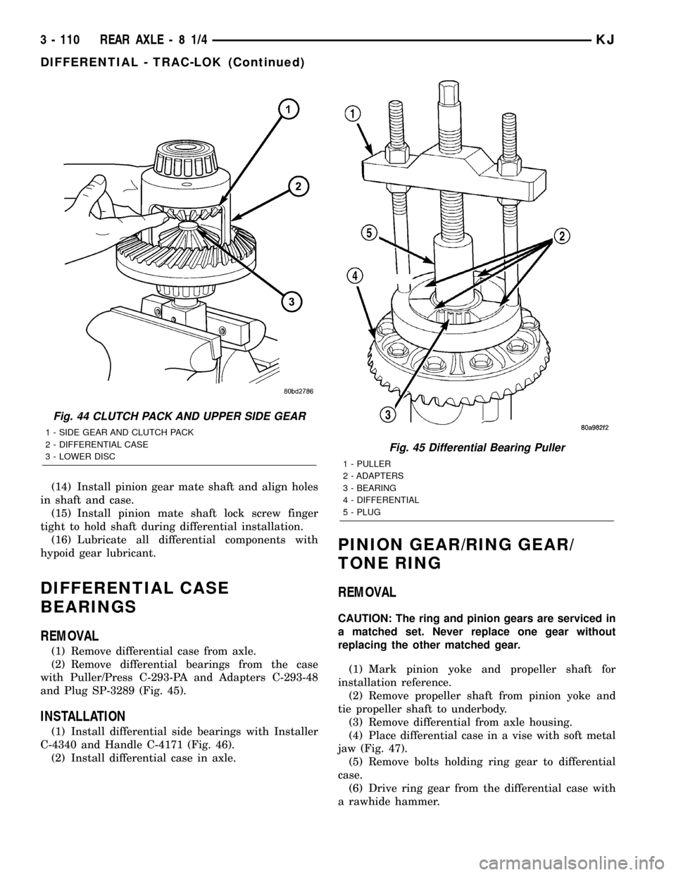
(14) Install pinion gear mate shaft and align holes
in shaft and case.
(15) Install pinion mate shaft lock screw finger
tight to hold shaft during differential installation.
(16) Lubricate all differential components with
hypoid gear lubricant.
DIFFERENTIAL CASE
BEARINGS
REMOVAL
(1) Remove differential case from axle.
(2) Remove differential bearings from the case
with Puller/Press C-293-PA and Adapters C-293-48
and Plug SP-3289 (Fig. 45).
INSTALLATION
(1) Install differential side bearings with Installer
C-4340 and Handle C-4171 (Fig. 46).
(2) Install differential case in axle.
PINION GEAR/RING GEAR/
TONE RING
REMOVAL
CAUTION: The ring and pinion gears are serviced in
a matched set. Never replace one gear without
replacing the other matched gear.
(1) Mark pinion yoke and propeller shaft for
installation reference.
(2) Remove propeller shaft from pinion yoke and
tie propeller shaft to underbody.
(3) Remove differential from axle housing.
(4) Place differential case in a vise with soft metal
jaw (Fig. 47).
(5) Remove bolts holding ring gear to differential
case.
(6) Drive ring gear from the differential case with
a rawhide hammer.
Fig. 44 CLUTCH PACK AND UPPER SIDE GEAR
1 - SIDE GEAR AND CLUTCH PACK
2 - DIFFERENTIAL CASE
3 - LOWER DISC
Fig. 45 Differential Bearing Puller
1 - PULLER
2 - ADAPTERS
3 - BEARING
4 - DIFFERENTIAL
5 - PLUG
3 - 110 REAR AXLE-81/4KJ
DIFFERENTIAL - TRAC-LOK (Continued)
Page 160 of 1803
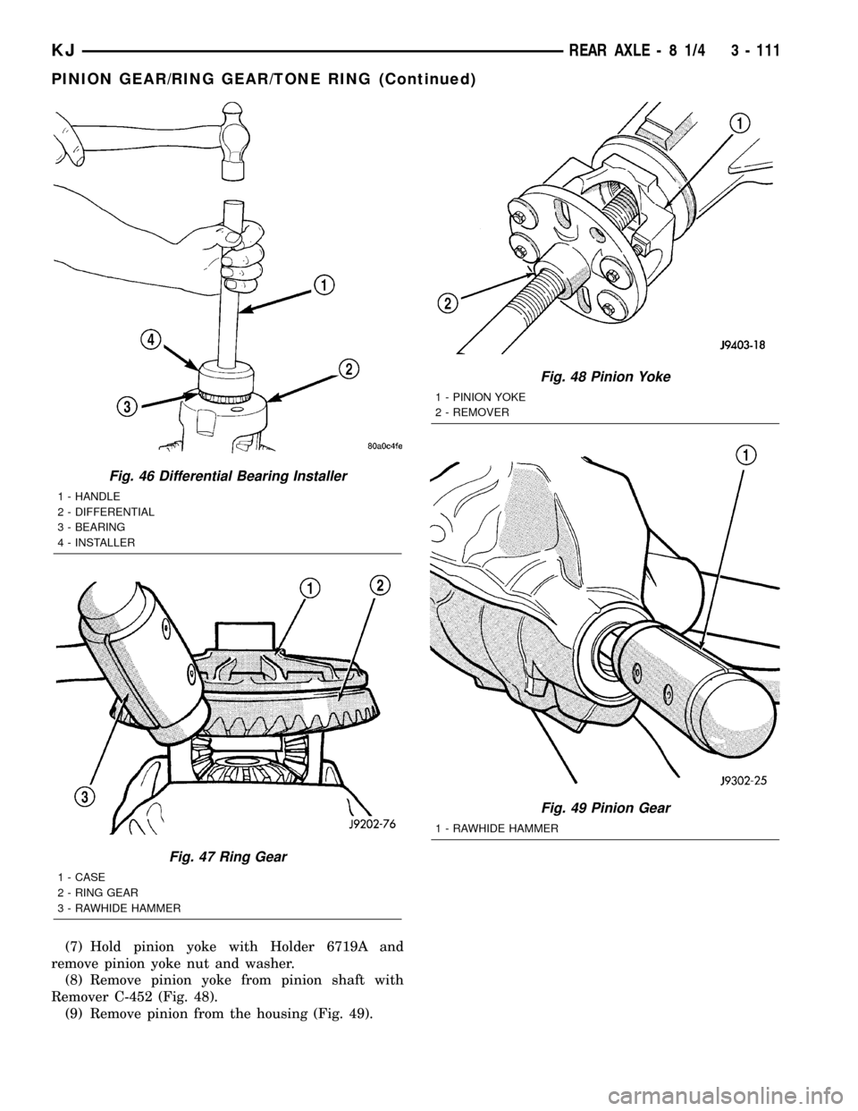
(7) Hold pinion yoke with Holder 6719A and
remove pinion yoke nut and washer.
(8) Remove pinion yoke from pinion shaft with
Remover C-452 (Fig. 48).
(9) Remove pinion from the housing (Fig. 49).
Fig. 46 Differential Bearing Installer
1 - HANDLE
2 - DIFFERENTIAL
3 - BEARING
4 - INSTALLER
Fig. 47 Ring Gear
1 - CASE
2 - RING GEAR
3 - RAWHIDE HAMMER
Fig. 48 Pinion Yoke
1 - PINION YOKE
2 - REMOVER
Fig. 49 Pinion Gear
1 - RAWHIDE HAMMER
KJREAR AXLE - 8 1/4 3 - 111
PINION GEAR/RING GEAR/TONE RING (Continued)
Page 161 of 1803
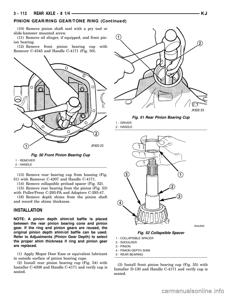
(10) Remove pinion shaft seal with a pry tool or
slide-hammer mounted screw.
(11) Remove oil slinger, if equipped, and front pin-
ion bearing.
(12) Remove front pinion bearing cup with
Remover C-4345 and Handle C-4171 (Fig. 50).
(13) Remove rear bearing cup from housing (Fig.
51) with Remover C-4307 and Handle C-4171.
(14) Remove collapsible preload spacer (Fig. 52).
(15) Remove rear bearing from the pinion (Fig. 53)
with Puller/Press C-293-PA and Adapters C-293-47.
(16) Remove depth shims from the pinion shaft
and record the shims thickness.
INSTALLATION
NOTE: A pinion depth shim/oil baffle is placed
between the rear pinion bearing cone and pinion
gear. If the ring and pinion gears are reused, the
original pinion depth shim/oil baffle can be used.
Refer to Adjustments (Pinion Gear Depth) to select
the proper shim thickness if ring and pinion gear
are replaced.
(1) Apply Mopar Door Ease or equivalent lubricant
to outside surface of pinion bearing cups.
(2) Install rear pinion bearing cup (Fig. 54) with
Installer C-4308 and Handle C-4171 and verify cup is
seated.(3) Install front pinion bearing cup (Fig. 55) with
Installer D-130 and Handle C-4171 and verify cup is
seated.
Fig. 50 Front Pinion Bearing Cup
1 - REMOVER
2 - HANDLE
Fig. 51 Rear Pinion Bearing Cup
1 - DRIVER
2 - HANDLE
Fig. 52 Collapsible Spacer
1 - COLLAPSIBLE SPACER
2 - SHOULDER
3 - PINION
4 - PINION DEPTH SHIM
5 - REAR BEARING
3 - 112 REAR AXLE-81/4KJ
PINION GEAR/RING GEAR/TONE RING (Continued)
Page 162 of 1803

(4) Install pinion front bearing and oil slinger, if
equipped.(5) Apply a light coating of gear lubricant on the
lip of pinion seal and install seal with Installer
C-4076-B and Handle C-4735 (Fig. 56).
(6) Place proper thickness depth shim on the pin-
ion.
(7) Install rear bearing and slinger if equipped, on
the pinion shaft (Fig. 57) with Installer 6448 and a
press.
(8) Install anewcollapsible preload spacer on pin-
ion shaft and install pinion in housing (Fig. 58).
(9) Install pinion in housing.
(10) Install yoke with Installer C-3718 and Yoke
Holder 6719A.
Fig. 53 Rear Pinion Bearing Puller
1 - PULLER
2 - VISE
3 - ADAPTERS
4 - PINION GEAR SHAFT
Fig. 54 Rear Pinion Bearing Cup
1 - INSTALLER
2 - HANDLE
Fig. 55 Front Bearing Cup
1 - INSTALLER
2 - HANDLE
Fig. 56 Pinion Seal
1 - HANDLE
2 - DIFFERENTIAL HOUSING
3 - INSTALLER
KJREAR AXLE - 8 1/4 3 - 113
PINION GEAR/RING GEAR/TONE RING (Continued)
Page 163 of 1803
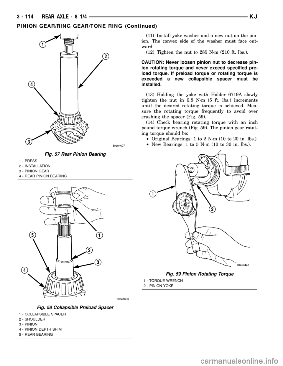
(11) Install yoke washer and a new nut on the pin-
ion. The convex side of the washer must face out-
ward.
(12) Tighten the nut to 285 N´m (210 ft. lbs.).
CAUTION: Never loosen pinion nut to decrease pin-
ion rotating torque and never exceed specified pre-
load torque. If preload torque or rotating torque is
exceeded a new collapsible spacer must be
installed.
(13) Holding the yoke with Holder 6719A slowly
tighten the nut in 6.8 N´m (5 ft. lbs.) increments
until the desired rotating torque is achieved. Mea-
sure the rotating torque frequently to avoid over
crushing the spacer (Fig. 59).
(14) Check bearing rotating torque with an inch
pound torque wrench (Fig. 59). The pinion gear rotat-
ing torque should be:
²Original Bearings: 1 to 2 N´m (10 to 20 in. lbs.).
²New Bearings: 1 to 5 N´m (10 to 30 in. lbs.).
Fig. 57 Rear Pinion Bearing
1 - PRESS
2 - INSTALLATION
3 - PINION GEAR
4 - REAR PINION BEARING
Fig. 58 Collapsible Preload Spacer
1 - COLLAPSIBLE SPACER
2 - SHOULDER
3 - PINION
4 - PINION DEPTH SHIM
5 - REAR BEARING
Fig. 59 Pinion Rotating Torque
1 - TORQUE WRENCH
2 - PINION YOKE
3 - 114 REAR AXLE-81/4KJ
PINION GEAR/RING GEAR/TONE RING (Continued)
Page 164 of 1803
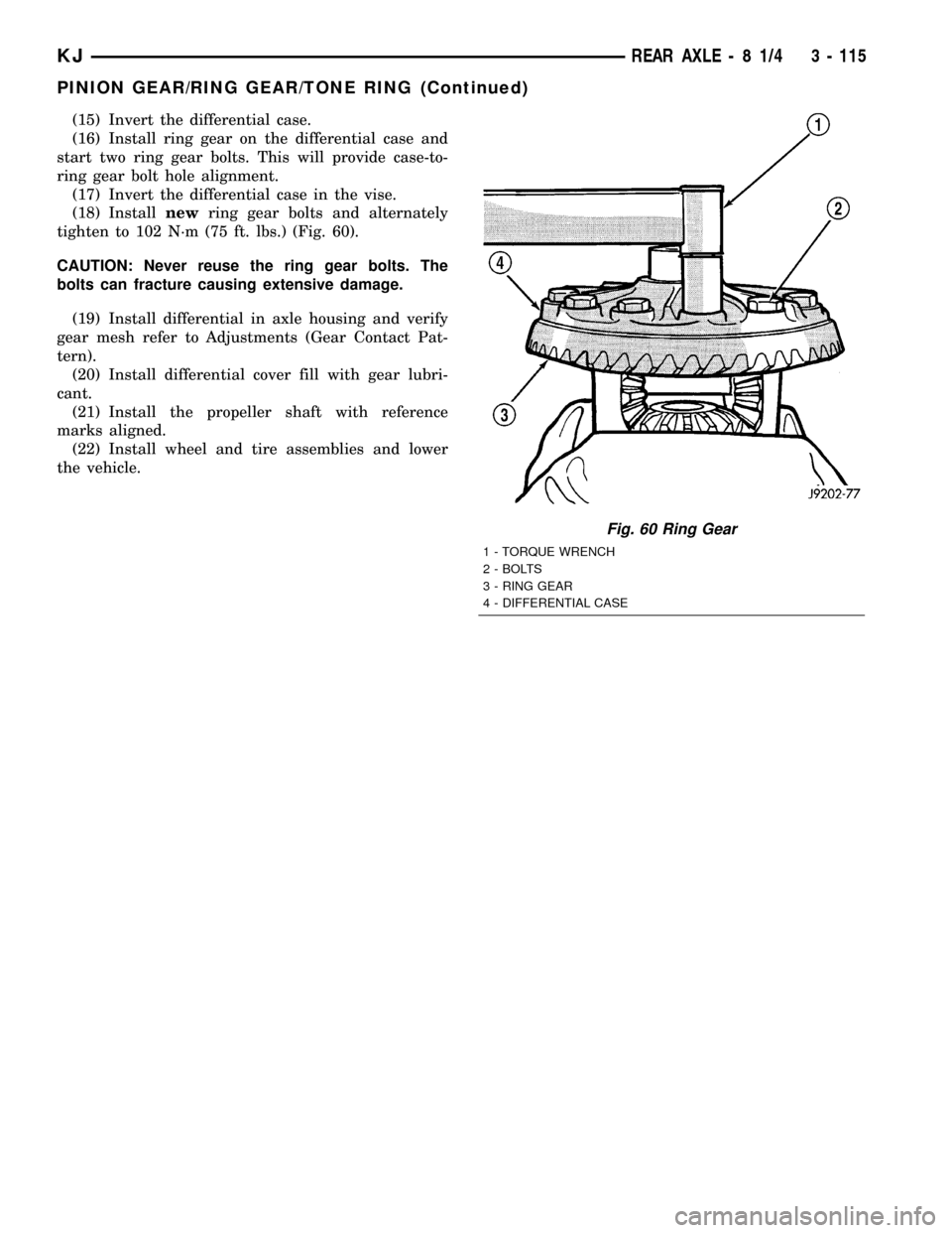
(15) Invert the differential case.
(16) Install ring gear on the differential case and
start two ring gear bolts. This will provide case-to-
ring gear bolt hole alignment.
(17) Invert the differential case in the vise.
(18) Installnewring gear bolts and alternately
tighten to 102 N´m (75 ft. lbs.) (Fig. 60).
CAUTION: Never reuse the ring gear bolts. The
bolts can fracture causing extensive damage.
(19) Install differential in axle housing and verify
gear mesh refer to Adjustments (Gear Contact Pat-
tern).
(20) Install differential cover fill with gear lubri-
cant.
(21) Install the propeller shaft with reference
marks aligned.
(22) Install wheel and tire assemblies and lower
the vehicle.
Fig. 60 Ring Gear
1 - TORQUE WRENCH
2 - BOLTS
3 - RING GEAR
4 - DIFFERENTIAL CASE
KJREAR AXLE - 8 1/4 3 - 115
PINION GEAR/RING GEAR/TONE RING (Continued)
Page 198 of 1803

ELECTRICAL
DESCRIPTION
Three wheel speed sensors are used. The front sen-
sors are mounted to the steering knuckles. The rear
sensor is mounted at the top of the rear axle differ-
ential carrier. Tone wheels are mounted to the out-
board ends of the front axle shafts. The gear type
tone wheel serves as the trigger mechanism for each
sensor.
OPERATION
The sensors convert wheel speed into a small digi-
tal signal. The CAB sends 12 volts to the sensors.
The sensor has an internal magneto resistance
bridge that alters the voltage and amperage of the
signal circuit. This voltage and amperage is changed
by magnetic induction when the toothed tone wheel
passes the wheel speed sensor. This digital signal is
sent to the CAB. The CAB measures the voltage and
amperage of the digital signal for each wheel.
FRONT WHEEL SPEED
SENSOR
REMOVAL
(1) Disconnect the front wheel speed sensor wire
connector that is located on the inboard side of the
respective wheel house.
(2) Raise and support the vehicle.
(3) Remove the tire and wheel assembly.
(4) Remove the caliper adapter. (Refer to 5 -
BRAKES/HYDRAULIC/MECHANICAL/DISC
BRAKE CALIPER ADAPTER - REMOVAL).
CAUTION: Never allow the disc brake caliper to
hang from the brake hose. Damage to the brake
hose with result. Provide a suitable support to hang
the caliper securely.
(5) Remove the disc brake rotor. (Refer to 5 -
BRAKES/HYDRAULIC/MECHANICAL/ROTORS -
REMOVAL).
(6) Remove the wheel speed sensor mounting bolt
to the hub (Fig. 1).
(7) Remove the wheel speed sensor wire from the
hub/bearing (Fig. 1).
(8) Remove the wheel speed sensor wire hold down
from the knuckle (Fig. 1).
(9) Remove the wheel speed sensor wire thru the
wheel well.
(10) Remove the wheel speed sensor from the vehi-
cle.
INSTALLATION
(1) Install the wheel speed sensor to the vehicle.
(2) Install the wheel speed sensor wire thru the
wheel well.
(3) Install the wheel speed sensor wire to the hub/
bearing.
(4) Install the wheel speed sensor wire hold down
to the knuckle.
(5) Install the wheel speed sensor mounting bolt to
the hub. Tighten the mounting bolt to 14 N´m (10
ft.lbs.).
(6) Install the disc brake rotor (Refer to 5 -
BRAKES/HYDRAULIC/MECHANICAL/ROTORS -
INSTALLATION).
(7) Install the disc brake caliper adapter. (Refer to
5 - BRAKES/HYDRAULIC/MECHANICAL/DISC
BRAKE CALIPER ADAPTER - INSTALLATION).
(8) Install the tire and wheel assembly (Refer to 22
- TIRES/WHEELS/WHEELS - STANDARD PROCE-
DURE).
(9) Reconnect the front wheel speed sensor wire
connector to the inboard side of the wheel house
being worked on.
Fig. 1 FRONT WHEEL SPEED SENSOR
1 - WHEEL SPEED SENSOR WIRE
2 - WHEEL SPEED SENSOR
3 - ROTOR
4 - WHEEL SPEED SENSOR WIRE HOLD DOWN
5 - 34 BRAKES - ABSKJ