2002 JEEP LIBERTY Fuel pump psi
[x] Cancel search: Fuel pump psiPage 1223 of 1803
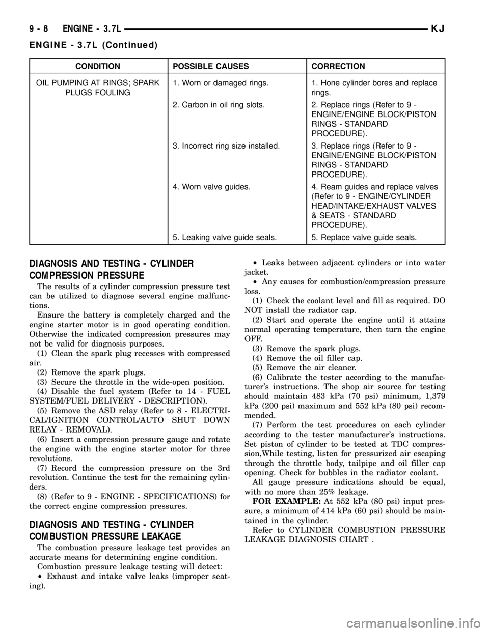
CONDITION POSSIBLE CAUSES CORRECTION
OIL PUMPING AT RINGS; SPARK
PLUGS FOULING1. Worn or damaged rings. 1. Hone cylinder bores and replace
rings.
2. Carbon in oil ring slots. 2. Replace rings (Refer to 9 -
ENGINE/ENGINE BLOCK/PISTON
RINGS - STANDARD
PROCEDURE).
3. Incorrect ring size installed. 3. Replace rings (Refer to 9 -
ENGINE/ENGINE BLOCK/PISTON
RINGS - STANDARD
PROCEDURE).
4. Worn valve guides. 4. Ream guides and replace valves
(Refer to 9 - ENGINE/CYLINDER
HEAD/INTAKE/EXHAUST VALVES
& SEATS - STANDARD
PROCEDURE).
5. Leaking valve guide seals. 5. Replace valve guide seals.
DIAGNOSIS AND TESTING - CYLINDER
COMPRESSION PRESSURE
The results of a cylinder compression pressure test
can be utilized to diagnose several engine malfunc-
tions.
Ensure the battery is completely charged and the
engine starter motor is in good operating condition.
Otherwise the indicated compression pressures may
not be valid for diagnosis purposes.
(1) Clean the spark plug recesses with compressed
air.
(2) Remove the spark plugs.
(3) Secure the throttle in the wide-open position.
(4) Disable the fuel system (Refer to 14 - FUEL
SYSTEM/FUEL DELIVERY - DESCRIPTION).
(5) Remove the ASD relay (Refer to 8 - ELECTRI-
CAL/IGNITION CONTROL/AUTO SHUT DOWN
RELAY - REMOVAL).
(6) Insert a compression pressure gauge and rotate
the engine with the engine starter motor for three
revolutions.
(7) Record the compression pressure on the 3rd
revolution. Continue the test for the remaining cylin-
ders.
(8) (Refer to 9 - ENGINE - SPECIFICATIONS) for
the correct engine compression pressures.
DIAGNOSIS AND TESTING - CYLINDER
COMBUSTION PRESSURE LEAKAGE
The combustion pressure leakage test provides an
accurate means for determining engine condition.
Combustion pressure leakage testing will detect:
²Exhaust and intake valve leaks (improper seat-
ing).²Leaks between adjacent cylinders or into water
jacket.
²Any causes for combustion/compression pressure
loss.
(1) Check the coolant level and fill as required. DO
NOT install the radiator cap.
(2) Start and operate the engine until it attains
normal operating temperature, then turn the engine
OFF.
(3) Remove the spark plugs.
(4) Remove the oil filler cap.
(5) Remove the air cleaner.
(6) Calibrate the tester according to the manufac-
turer's instructions. The shop air source for testing
should maintain 483 kPa (70 psi) minimum, 1,379
kPa (200 psi) maximum and 552 kPa (80 psi) recom-
mended.
(7) Perform the test procedures on each cylinder
according to the tester manufacturer's instructions.
Set piston of cylinder to be tested at TDC compres-
sion,While testing, listen for pressurized air escaping
through the throttle body, tailpipe and oil filler cap
opening. Check for bubbles in the radiator coolant.
All gauge pressure indications should be equal,
with no more than 25% leakage.
FOR EXAMPLE:At 552 kPa (80 psi) input pres-
sure, a minimum of 414 kPa (60 psi) should be main-
tained in the cylinder.
Refer to CYLINDER COMBUSTION PRESSURE
LEAKAGE DIAGNOSIS CHART .
9 - 8 ENGINE - 3.7LKJ
ENGINE - 3.7L (Continued)
Page 1235 of 1803
Possible indications of the cylinder head gasket
leaking between adjacent cylinders are:
²Loss of engine power
²Engine misfiring
²Poor fuel economy
Possible indications of the cylinder head gasket
leaking between a cylinder and an adjacent water
jacket are:
²Engine overheating
²Loss of coolant
²Excessive steam (white smoke) emitting from
exhaust
²Coolant foaming
CYLINDER-TO-CYLINDER LEAKAGE TEST
To determine if an engine cylinder head gasket is
leaking between adjacent cylinders, follow the proce-
dures in Cylinder Compression Pressure Test (Refer
to 9 - ENGINE - DIAGNOSIS AND TESTING). An
engine cylinder head gasket leaking between adja-
cent cylinders will result in approximately a 50±70%
reduction in compression pressure.
CYLINDER-TO-WATER JACKET LEAKAGE TEST
WARNING: USE EXTREME CAUTION WHEN THE
ENGINE IS OPERATING WITH COOLANT PRES-
SURE CAP REMOVED.
VISUAL TEST METHOD
With the engine cool, remove the coolant pressure
cap. Start the engine and allow it to warm up until
thermostat opens.
If a large combustion/compression pressure leak
exists, bubbles will be visible in the coolant.
COOLING SYSTEM TESTER METHOD
WARNING: WITH COOLING SYSTEM TESTER IN
PLACE, PRESSURE WILL BUILD UP FAST. EXCES-
SIVE PRESSURE BUILT UP, BY CONTINUOUS
ENGINE OPERATION, MUST BE RELEASED TO A
SAFE PRESSURE POINT. NEVER PERMIT PRES-
SURE TO EXCEED 138 kPa (20 psi).
Install Cooling System Tester 7700 or equivalent to
pressure cap neck. Start the engine and observe the
tester's pressure gauge. If gauge pulsates with every
power stroke of a cylinder a combustion pressure
leak is evident.
CHEMICAL TEST METHOD
Combustion leaks into the cooling system can also
be checked by using Bloc-Chek Kit C-3685-A or
equivalent. Perform test following the procedures
supplied with the tool kit.
REMOVAL
(1) Disconnect the negative cable from the battery.
(2) Raise the vehicle on a hoist.
(3) Disconnect the exhaust pipe at the left side
exhaust manifold.
(4) Drain the engine coolant. Refer to COOLING
SYSTEM.
(5) Lower the vehicle.
(6) Remove the intake manifold. Refer to proce-
dure in this section.
(7) Remove the cylinder head cover. Refer to proce-
dure in this section.
(8) Remove the fan shroud and fan blade assembly.
Refer to COOLING SYSTEM.
(9) Remove accessory drive belt. Refer to COOL-
ING SYSTEM.
(10) Remove the power steering pump and set
aside.
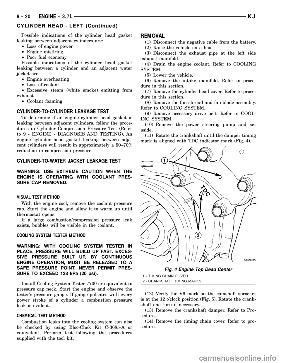
(11) Rotate the crankshaft until the damper timing
mark is aligned with TDC indicator mark (Fig. 4).
(12) Verify the V6 mark on the camshaft sprocket
is at the 12 o'clock position (Fig. 5). Rotate the crank-
shaft one turn if necessary.
(13) Remove the crankshaft damper. Refer to Pro-
cedure.
(14) Remove the timing chain cover. Refer to pro-
cedure.
Fig. 4 Engine Top Dead Center
1 - TIMING CHAIN COVER
2 - CRANKSHAFT TIMING MARKS
9 - 20 ENGINE - 3.7LKJ
CYLINDER HEAD - LEFT (Continued)
Page 1310 of 1803
(8) Install the starter.
(9) Connect the crankshaft position sensor.
(10) Install the engine block heater power cable, if
equipped.
CAUTION: The structural cover requires a specific
torque sequence. Failure to follow this sequence
may cause severe damage to the cover.
(11) Install the structural cover.
(12) Install the exhaust pipe.
(13) Connect the oxygen sensors.
(14) Lower vehicle.
(15) Connect the knock sensors.
(16) Connect the engine to body ground straps.
(17) Install the power brake booster vacuum hose.
(18) Install the breather hoses.
(19) Install the PCV hose.
(20) Install the fuel rail.
(21) Install the coil over plugs.
(22) Reconnect the engine wiring harness at the
following points:
²Intake air temperature (IAT) sensor
²Fuel Injectors
²Throttle Position (TPS) Switch
²Idle Air Control (IAC) Motor
²Engine Oil Pressure Switch
²Engine Coolant Temperature (ECT) Sensor
²Manifold Absolute Pressure MAP) Sensor
²Camshaft Position (CMP) Sensor
²Coil Over Plugs
²Crankshaft Position Sensor
(23) Connect lower radiator hose.
(24) Connect upper radiator hose.
(25) Connect throttle and speed control cables.
(26) Install the heater hose assembly.
(27) Install coolant recovery bottle.
(28) Install the power steering pump.
(29) Install the generator.
(30) Install the A/C compressor.
(31) Install the drive belt.
(32) Install the fan shroud with the electric fan
assembly.
(33) Install the radiator core support bracket.
(34) Install the air cleaner assembly.
(35) Refill the engine cooling system.
(36) Install the hood.
(37) Check and fill engine oil.
(38) Connect the battery negative cable.
(39) Start the engine and check for leaks.SPECIFICATIONS
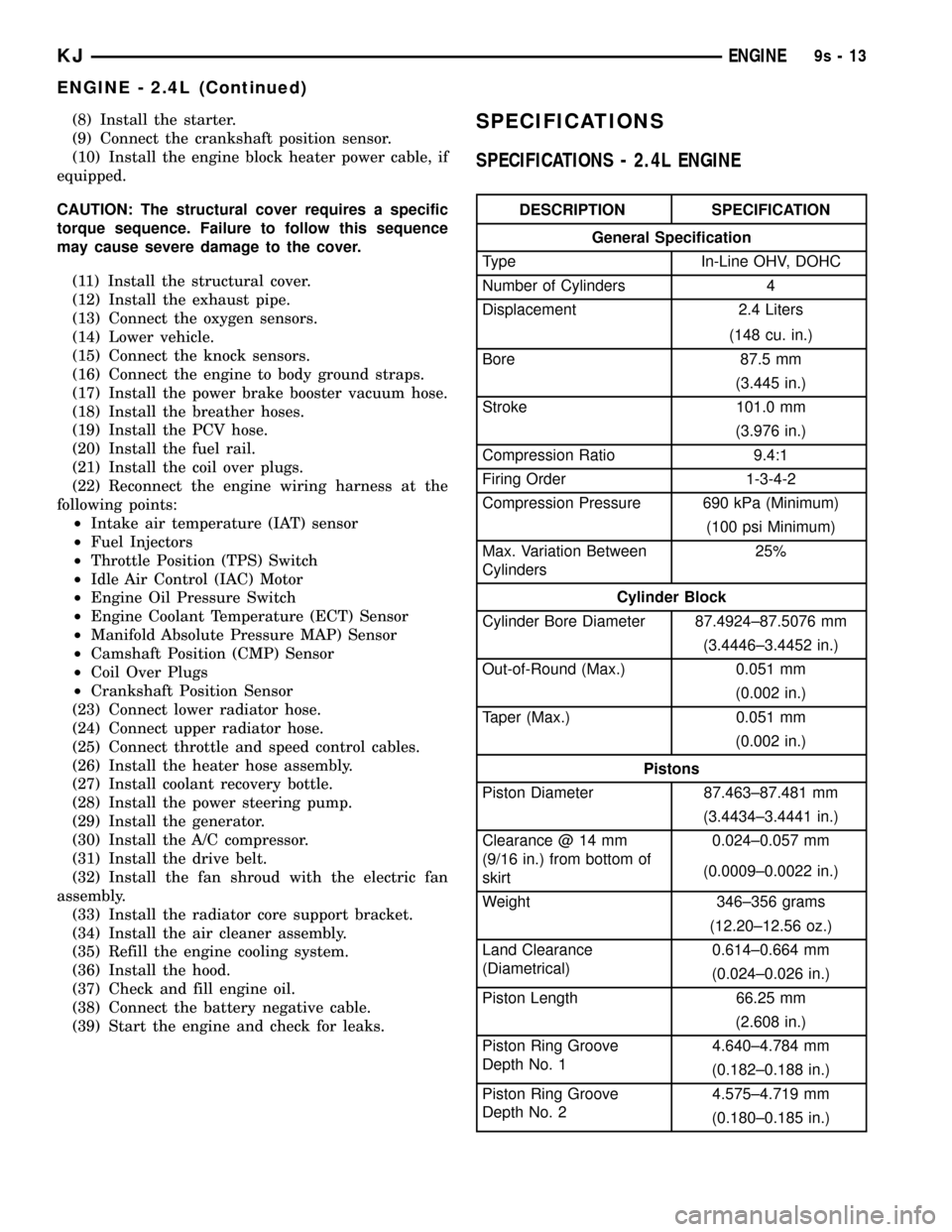
SPECIFICATIONS - 2.4L ENGINE
DESCRIPTION SPECIFICATION
General Specification
Type In-Line OHV, DOHC
Number of Cylinders 4
Displacement 2.4 Liters
(148 cu. in.)
Bore 87.5 mm
(3.445 in.)
Stroke 101.0 mm
(3.976 in.)
Compression Ratio 9.4:1
Firing Order 1-3-4-2
Compression Pressure 690 kPa (Minimum)
(100 psi Minimum)
Max. Variation Between
Cylinders25%
Cylinder Block
Cylinder Bore Diameter 87.4924±87.5076 mm
(3.4446±3.4452 in.)
Out-of-Round (Max.) 0.051 mm
(0.002 in.)
Taper (Max.) 0.051 mm
(0.002 in.)
Pistons
Piston Diameter 87.463±87.481 mm
(3.4434±3.4441 in.)
Clearance @ 14 mm
(9/16 in.) from bottom of
skirt0.024±0.057 mm
(0.0009±0.0022 in.)
Weight 346±356 grams
(12.20±12.56 oz.)
Land Clearance
(Diametrical)0.614±0.664 mm
(0.024±0.026 in.)
Piston Length 66.25 mm
(2.608 in.)
Piston Ring Groove
Depth No. 14.640±4.784 mm
(0.182±0.188 in.)
Piston Ring Groove
Depth No. 24.575±4.719 mm
(0.180±0.185 in.)
KJENGINE9s-13
ENGINE - 2.4L (Continued)
Page 1317 of 1803
Possible indications of the cylinder head gasket
leaking between a cylinder and an adjacent water
jacket are:
²Engine overheating
²Loss of coolant
²Excessive steam (white smoke) emitting from
exhaust
²Coolant foaming
CYLINDER-TO-CYLINDER LEAKAGE TEST
To determine if an engine cylinder head gasket is
leaking between adjacent cylinders, follow the proce-
dures in Cylinder Compression Pressure Test (Refer
to 9 - ENGINE - DIAGNOSIS AND TESTING). An
engine cylinder head gasket leaking between adja-
cent cylinders will result in approximately a 50±70%
reduction in compression pressure.
CYLINDER-TO-WATER JACKET LEAKAGE TEST
WARNING: USE EXTREME CAUTION WHEN THE
ENGINE IS OPERATING WITH COOLANT PRES-
SURE CAP REMOVED.
VISUAL TEST METHOD
With the engine cool, remove the coolant pressure
cap. Start the engine and allow it to warm up until
thermostat opens.
If a large combustion/compression pressure leak
exists, bubbles will be visible in the coolant.
COOLING SYSTEM TESTER METHOD
WARNING: WITH COOLING SYSTEM TESTER IN
PLACE, PRESSURE WILL BUILD UP FAST. EXCES-
SIVE PRESSURE BUILT UP, BY CONTINUOUS
ENGINE OPERATION, MUST BE RELEASED TO A
SAFE PRESSURE POINT. NEVER PERMIT PRES-
SURE TO EXCEED 138 kPa (20 psi).
Install Cooling System Tester 7700 or equivalent to
pressure cap neck. Start the engine and observe the
tester's pressure gauge. If gauge pulsates with every
power stroke of a cylinder a combustion pressure
leak is evident.
CHEMICAL TEST METHOD
Combustion leaks into the cooling system can also
be checked by using Bloc-Chek Kit C-3685-A or
equivalent. Perform test following the procedures
supplied with the tool kit.
REMOVAL - CYLINDER HEAD
(1) Perform fuel system pressure release procedure
before attempting any repairs.(Refer to 14 -FUEL SYSTEM/FUEL DELIVERY - SPECIFICA-
TIONS)
(2) Disconnect battery negative cable.
(3) Drain cooling system. (Refer to 7 - COOLING -
STANDARD PROCEDURE)
(4) Remove air filter housing and inlet tube.
(5) Remove intake manifold.
(6) Remove heater tube support bracket from cyl-
inder head.
(7) Disconnect radiator upper and heater supply
hoses from water outlet connections.
(8) Remove accessory drive belts. (Refer to 7 -
COOLING/ACCESSORY DRIVE/DRIVE BELTS -
REMOVAL)
(9) Raise vehicle and remove exhaust pipe from
manifold.
(10) Remove power steering pump and set aside.
Do not disconnect lines.
(11) Remove accessory drive bracket
(12) Remove ignition coil and wires from engine.
(13) Disconnect cam sensor and fuel injector wir-
ing connectors.
(14) Remove timing belt and camshaft sprockets.
(Refer to 9 - ENGINE/VALVE TIMING/TIMING
BELT/CHAIN AND SPROCKETS - REMOVAL)
(15) Remove timing belt idler pulley and rear tim-
ing belt cover. (Refer to 9 - ENGINE/VALVE TIM-
ING/TIMING BELT / CHAIN COVER(S) -
REMOVAL)
(16) Remove cylinder head cover. (Refer to 9 -
ENGINE/CYLINDER HEAD/CYLINDER HEAD
COVER(S) - REMOVAL)
(17) Remove camshafts (Refer to 9 - ENGINE/
CYLINDER HEAD/CAMSHAFT(S) - REMOVAL).
NOTE: Identify rocker arm position to ensure cor-
rect re-installation in original position, if reused.
(18) Remove rocker arms. (Refer to 9 - ENGINE/
CYLINDER HEAD/ROCKER ARMS - REMOVAL).
(19) Remove cylinder head bolts in REVERSE
sequence of tightening.
(20) Remove cylinder head from engine block.
(21) Inspect and clean cylinder head. (Refer to 9 -
ENGINE/CYLINDER HEAD - INSPECTION) (Refer
to 9 - ENGINE/CYLINDER HEAD - CLEANING)
CLEANING
To ensure engine gasket sealing, proper surface
preparation must be performed, especially with the
use of aluminum engine components and multi-layer
steel cylinder head gaskets.
NOTE: Multi-Layer Steel (MLS) head gaskets require
a scratch free sealing surface.
9s - 20 ENGINEKJ
CYLINDER HEAD (Continued)
Page 1385 of 1803
OPERATION
Fuel is picked up in the fuel tank by the fuel pump
module. This module is located on the bottom of the
fuel tank.
A fuel return system is provided within the fuel
pump module using check valves. A separate fuel
return line from the engine to the tank is not used.
The fuel pressure regulator and the main fuel filter
are not combined. They are separate items.
The fuel tank assembly consists of: the fuel tank,
fuel pump module assembly, fuel pump module lock
ring/gasket, ORVR components. Refer to 25, Emis-
sion Control System for ORVR information.
A fuel filler/vent tube assembly using a pressure/
vacuum, 1/4 turn fuel filler cap is used. The fuel
filler tube contains a flap door located below the fuel
fill cap. A one-way check valve is installed into the
tanks fuel fill fitting.
Also to be considered part of the fuel system is the
evaporation control system and ORVR system. This
is designed to reduce the emission of fuel vapors into
the atmosphere. The description and function of the
Evaporative Control System is found in 25, Emission
Control Systems.
Both fuel filters (mounted to front of fuel tank, and
inside the bottom fuel pump module) are designed for
extended service. They do not require normal sched-
uled maintenance. The bottom section of the fuel
pump module (with included filter) should only be
replaced if a diagnostic procedure indicates to do so.
Also, the fuel filter mounted to the front of the fuel
tank should only be replaced if a diagnostic proce-
dure indicates to do so.
DIAGNOSIS AND TESTING - FUEL PRESSURE
LEAK DOWN TEST
Use this test in conjunction with the Fuel Pump
Pressure Test and Fuel Pump Capacity Test.
Check Valve Operation:The electric fuel pump
outlet contains a one-way check valve to prevent fuel
flow back into the tank and to maintain fuel supply
line pressure (engine warm) when pump is not oper-
ational. It is also used to keep the fuel supply line
full of gasoline when pump is not operational. After
the vehicle has cooled down, fuel pressure may drop
to 0 psi (cold fluid contracts), but liquid gasoline will
remain in fuel supply line between the check valve
and fuel injectors.Fuel pressure that has
dropped to 0 psi on a cooled down vehicle
(engine off) is a normal condition.When the elec-
tric fuel pump is activated, fuel pressure should
immediately(1±2 seconds) rise to specification.
Abnormally long periods of cranking to restart a
hotengine that has been shut down for a short
period of time may be caused by:
²Fuel pressure bleeding past a fuel injector(s).²Fuel pressure bleeding past the check valve in
the fuel pump module.
(1) Disconnect the fuel inlet line at fuel rail. Refer
to Quick Connect Fittings for procedures. On some
engines, air cleaner housing removal may be neces-
sary before fuel line disconnection.
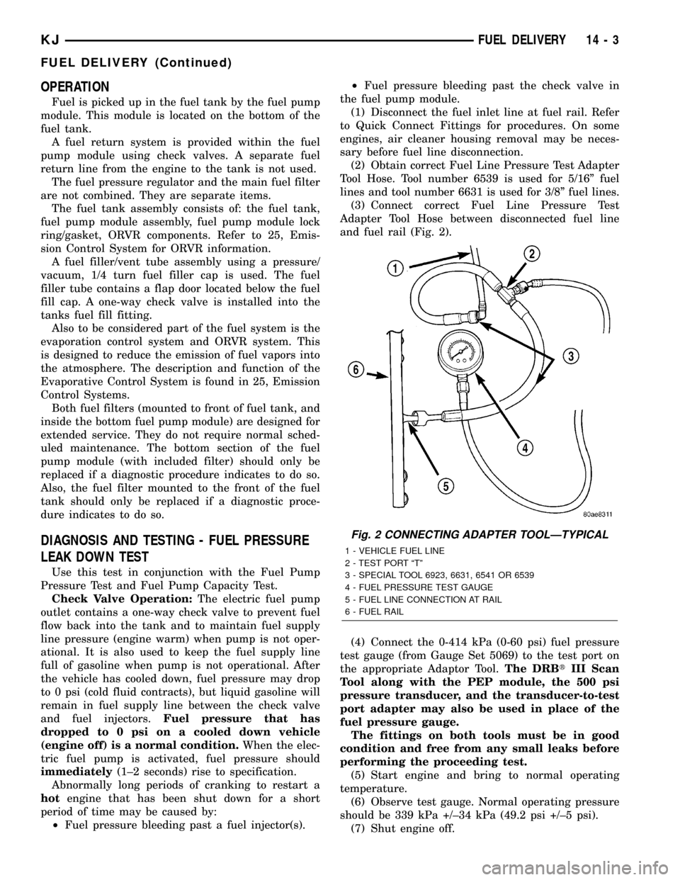
(2) Obtain correct Fuel Line Pressure Test Adapter
Tool Hose. Tool number 6539 is used for 5/16º fuel
lines and tool number 6631 is used for 3/8º fuel lines.
(3) Connect correct Fuel Line Pressure Test
Adapter Tool Hose between disconnected fuel line
and fuel rail (Fig. 2).
(4) Connect the 0-414 kPa (0-60 psi) fuel pressure
test gauge (from Gauge Set 5069) to the test port on
the appropriate Adaptor Tool.The DRBtIII Scan
Tool along with the PEP module, the 500 psi
pressure transducer, and the transducer-to-test
port adapter may also be used in place of the
fuel pressure gauge.
The fittings on both tools must be in good
condition and free from any small leaks before
performing the proceeding test.
(5) Start engine and bring to normal operating
temperature.
(6) Observe test gauge. Normal operating pressure
should be 339 kPa +/±34 kPa (49.2 psi +/±5 psi).
(7) Shut engine off.
Fig. 2 CONNECTING ADAPTER TOOLÐTYPICAL
1 - VEHICLE FUEL LINE
2 - TEST PORT ªTº
3 - SPECIAL TOOL 6923, 6631, 6541 OR 6539
4 - FUEL PRESSURE TEST GAUGE
5 - FUEL LINE CONNECTION AT RAIL
6 - FUEL RAIL
KJFUEL DELIVERY 14 - 3
FUEL DELIVERY (Continued)
Page 1386 of 1803
(8) Pressure should not fall below30 psi for five
minutes.
(9) If pressure falls below 30 psi, it must be deter-
mined if a fuel injector, the check valve within the
fuel pump module, or a fuel tube/line is leaking.
(10) Again, start engine and bring to normal oper-
ating temperature.
(11) Shut engine off.
(12)Testing for fuel injector or fuel rail leak-
age:Clamp off the rubber hose portion of Adaptor
Tool between the fuel rail and the test port ªTº on
Adapter Tool. If pressure now holds at or above 30
psi, a fuel injector or the fuel rail is leaking.
(13)Testing for fuel pump check valve, filter,
regulator check valve or fuel tube/line leakage:
Clamp off the rubber hose portion of Adaptor Tool
between the vehicle fuel line and test port ªTº on
Adapter Tool. If pressure now holds at or above 30
psi, a leak may be found at a fuel tube/line. If no
leaks are found at fuel tubes or lines, one of the
check valves in either the electric fuel pump, fuel fil-
ter or fuel pressure regulator may be leaking.
Note: A quick loss of pressure usually indicates a
defective check valve in the pressure regulator. A
slow loss of pressure usually indicates a defective
check valve in the bottom of the fuel pump module.
The check valves are not serviced separately. Also,
the electric fuel pump is not serviced separately.
STANDARD PROCEDURE - FUEL SYSTEM
PRESSURE RELEASE
Use following procedure if the fuel injector
rail is, or is not equipped with a fuel pressure
test port.
(1) Remove fuel fill cap.
(2) Remove fuel pump relay from Power Distribu-
tion Center (PDC). For location of relay, refer to label
on underside of PDC cover.(3) Start and run engine until it stalls.
(4) Attempt restarting engine until it will no
longer run.
(5) Turn ignition key to OFF position.
CAUTION: Steps 1, 2, 3 and 4 must be performed to
relieve high pressure fuel from within fuel rail. Do
not attempt to use following steps to relieve this
pressure as excessive fuel will be forced into a cyl-
inder chamber.
(6) Unplug connector from any fuel injector.
(7) Attach one end of a jumper wire with alligator
clips (18 gauge or smaller) to either injector terminal.
(8) Connect other end of jumper wire to positive
side of battery.
(9) Connect one end of a second jumper wire to
remaining injector terminal.
CAUTION: Powering an injector for more than a few
seconds will permanently damage the injector.
(10) Momentarily touch other end of jumper wire
to negative terminal of battery for no more than a
few seconds.
(11) Place a rag or towel below fuel line quick-con-
nect fitting at fuel rail.
(12) Disconnect quick-connect fitting at fuel rail.
Refer to Quick-Connect Fittings.
(13) Return fuel pump relay to PDC.
(14) One or more Diagnostic Trouble Codes (DTC's)
may have been stored in PCM memory due to fuel
pump relay removal. The DRBtscan tool must be
used to erase a DTC.
14 - 4 FUEL DELIVERYKJ
FUEL DELIVERY (Continued)
Page 1387 of 1803
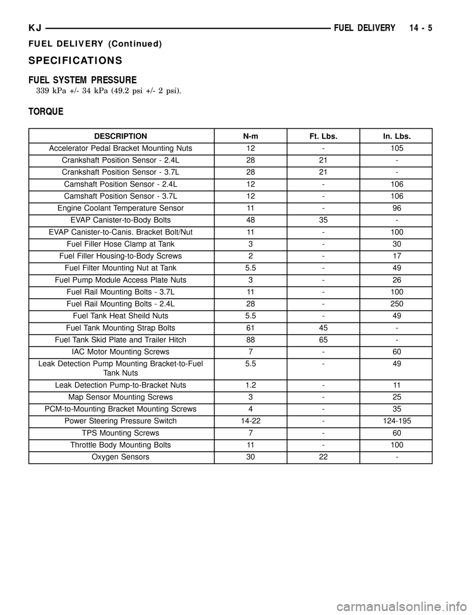
SPECIFICATIONS
FUEL SYSTEM PRESSURE
339 kPa +/- 34 kPa (49.2 psi +/- 2 psi).
TORQUE
DESCRIPTION N-m Ft. Lbs. In. Lbs.
Accelerator Pedal Bracket Mounting Nuts 12 - 105
Crankshaft Position Sensor - 2.4L 28 21 -
Crankshaft Position Sensor - 3.7L 28 21 -
Camshaft Position Sensor - 2.4L 12 - 106
Camshaft Position Sensor - 3.7L 12 - 106
Engine Coolant Temperature Sensor 11 - 96
EVAP Canister-to-Body Bolts 48 35 -
EVAP Canister-to-Canis. Bracket Bolt/Nut 11 - 100
Fuel Filler Hose Clamp at Tank 3 - 30
Fuel Filler Housing-to-Body Screws 2 - 17
Fuel Filter Mounting Nut at Tank 5.5 - 49
Fuel Pump Module Access Plate Nuts 3 - 26
Fuel Rail Mounting Bolts - 3.7L 11 - 100
Fuel Rail Mounting Bolts - 2.4L 28 - 250
Fuel Tank Heat Sheild Nuts 5.5 - 49
Fuel Tank Mounting Strap Bolts 61 45 -
Fuel Tank Skid Plate and Trailer Hitch 88 65 -
IAC Motor Mounting Screws 7 - 60
Leak Detection Pump Mounting Bracket-to-Fuel
Tank Nuts5.5 - 49
Leak Detection Pump-to-Bracket Nuts 1.2 - 11
Map Sensor Mounting Screws 3 - 25
PCM-to-Mounting Bracket Mounting Screws 4 - 35
Power Steering Pressure Switch 14-22 - 124-195
TPS Mounting Screws 7 - 60
Throttle Body Mounting Bolts 11 - 100
Oxygen Sensors 30 22 -
KJFUEL DELIVERY 14 - 5
FUEL DELIVERY (Continued)
Page 1396 of 1803
OPERATION
The fuel pressure regulator is a mechanical device
that is not controlled by engine vacuum or the Pow-
ertrain Control Module (PCM).
The regulator is calibrated to maintain fuel system
operating pressure of approximately 339 kPa +/- 34
kPa (49.2 psi +/- 5 psi) at the fuel injectors. It con-
tains a diaphragm, calibrated springs and a fuel
return valve.
The main fuel filteris not combinedwithin the
fuel pressure regulator as in other Jeeptmodels.
Three different fuel filters are used: 1. a serviceable,
separate, externally mounted, main fuel filter; 2. a
non-serviceable primary filter located on the bottom
of the electric fuel pump; 3. a non-serviceable second-
ary filter attached to the side of the fuel pump mod-
ule.
Fuel Flow:Fuel migrates into the fuel pump mod-
ule reservoir through a one-way check valve located
on the bottom of the module. This check valve pre-
vents the reservoir from running empty such as
when going up or down hills with a low amount of
fuel in the tank. A primary fuel filter (sock) is located
at the bottom of the electric fuel pump. Fuel is drawn
in through this filter, and up to the electric fuel
pump. High pressure fuel (unregulated) is supplied
from the electric fuel pump through a high-pressure
line to one of 3 fittings on the main fuel filter. If fuel
pressure at the pressure regulator exceeds approxi-
mately 49 psi, an internal diaphragm within the reg-
ulator closes, and excess fuel is routed through a
second fitting on the main fuel filter, and back into
the fuel tank (the fuel pressure regulator is installed
into the return side of the system). Pressure regu-
lated fuel is then delivered from the third fitting on
the fuel filter, up to and through the fuel rail, and on
to the fuel injectors.
A secondary fuel filter is attached to the side of the
fuel pump module. High-pressure from the electric
fuel pump causes a siphoning action across a passage
connected to this filter, and fuel is drawn into the
fuel pump module reservoir. This is used to help keep
the module reservoir full of fuel.
The fuel pressure regulator also acts as a check
valve to maintain some fuel pressure when the
engine is not operating. This will help to start the
engine. A second check valve is located at the outlet
of the fuel pump module housing.Refer to Fuel
Pump - Description and Operation for more
information. Also refer to the Fuel Pressure
Leak Down Test, and the Fuel Pump Pressure
Tests.
A separate fuel return line from the engine is not
used with this system.
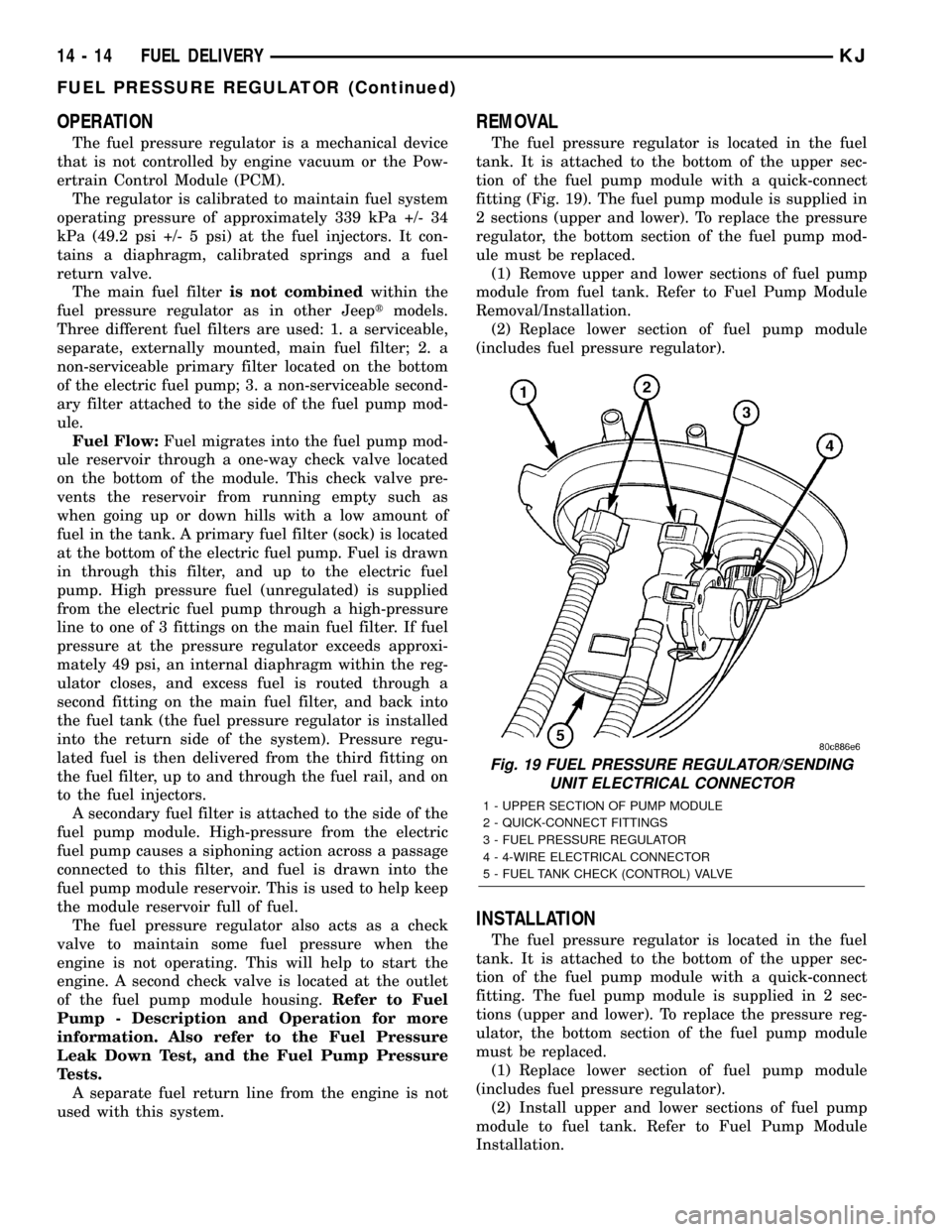
REMOVAL
The fuel pressure regulator is located in the fuel
tank. It is attached to the bottom of the upper sec-
tion of the fuel pump module with a quick-connect
fitting (Fig. 19). The fuel pump module is supplied in
2 sections (upper and lower). To replace the pressure
regulator, the bottom section of the fuel pump mod-
ule must be replaced.
(1) Remove upper and lower sections of fuel pump
module from fuel tank. Refer to Fuel Pump Module
Removal/Installation.
(2) Replace lower section of fuel pump module
(includes fuel pressure regulator).
INSTALLATION
The fuel pressure regulator is located in the fuel
tank. It is attached to the bottom of the upper sec-
tion of the fuel pump module with a quick-connect
fitting. The fuel pump module is supplied in 2 sec-
tions (upper and lower). To replace the pressure reg-
ulator, the bottom section of the fuel pump module
must be replaced.
(1) Replace lower section of fuel pump module
(includes fuel pressure regulator).
(2) Install upper and lower sections of fuel pump
module to fuel tank. Refer to Fuel Pump Module
Installation.
Fig. 19 FUEL PRESSURE REGULATOR/SENDING
UNIT ELECTRICAL CONNECTOR
1 - UPPER SECTION OF PUMP MODULE
2 - QUICK-CONNECT FITTINGS
3 - FUEL PRESSURE REGULATOR
4 - 4-WIRE ELECTRICAL CONNECTOR
5 - FUEL TANK CHECK (CONTROL) VALVE
14 - 14 FUEL DELIVERYKJ
FUEL PRESSURE REGULATOR (Continued)