Page 1604 of 2100

Chart 15a: Possible Causes of Low Line Pressure
StepActionYe sNo
1Check oil level.
Was the problem found?
Fill with ATFGo to Step 2
2Check for defective throttl")
7A±20
AUTOMATIC TRANSMISSION (4L30±E)
Chart 15a: Possible Causes of Low Line Pressure
StepActionYe sNo
1Check oil level.
Was the problem found?
Fill with ATFGo to Step 2
2Check for defective throttle position sensor.
Was the problem found?Replace throttle
position sensor
Go to Step 3
3Check for plugged, loose, or damaged oil filter (79).
Was the problem found?Inspect oil filter,
tighten bolts or
replace oil filter
(79)
Go to Step 4
4Check for a stuck force motor plunger (404). (Adapter case valve
body)
Was the problem found?Replace force
motor plunger
(404)
Go to Step 5
5Check for a stuck feed limit valve (412). (Adapter case valve body)
Was the problem found?Replace feed limit
valve (412)
Go to Step 6
6Check for loose converter bolts (4 & 5).
Was the problem found?Tighten converter
bolts (4 & 5)
Go to Step 7
7Check for a stuck pressure regulator valve (217). (Oil pump)
Was the problem found?Replace pressure
regulator valve
(217)
Go to Step 8
8Check for a stuck boost valve (213).(Oil pump)
Was the problem found?Replace boost
valve (213)
Go to Step 9
9Check for blocked intermediate oil passages to pressure
regulator valve. (Oil pump)
Was the problem found?
Replace oil pumpGo to Step 10
10Check for defective oil pump (9, 201, 202 & 228).
Was the problem found?
Replace oil pumpGo to Step 11
11Check for internal leaks.
± Check balls missing or out of location in valve bodies
± Seals cut or damaged
± Gaskets defective, etc.
Was the problem found?Install balls, or
correct ball
location
Replace seals
Replace gaskets
Ð
Page 1605 of 2100

Chart 15b: Possible Causes Of High Line Pressure
NOTE: If transmission is operating in backup mode, high
line pressure will be present.
Step
ActionYe sNo
1Check")
7A±21 AUTOMATIC TRANSMISSION (4L30±E)
Chart 15b: Possible Causes Of High Line Pressure
NOTE: If transmission is operating in backup mode, high
line pressure will be present.
Step
ActionYe sNo
1Check for defective throttle position sensor.
Was the problem found?Replace throttle
position sensor.
Go to Step 2.
2Check for a stuck force motor plunger (404). (Open
circuit/intermittent) (Adapter case valve body)
Was the problem found?Replace force
motor plunger
(404)
Go to Step 3
3Check for a stuck feed limit valve (412). (Adapter case valve body)
Was the problem found?Replace force
motor plunger
(412)
Go to Step 4
4Check converter bolts (4 & 5).
Was the problem found?Tighten converter
bolts (4 & 5)
Go to Step 5
5Check for a stuck pressure regulator valve (217). (Oil pump)
Was the problem found?Replace pressure
regulator valve
(217)
Go to Step 6
6Check for a stuck boost valve (213). (Oil pump)
Was the problem found?Replace boost
valve (213)
Go to Step 7
7Check for internal leaks.
± Check balls missing or out of location in valve bodies
± Seals cut or missing
± Gaskets defective, etc.
Was the problem found?Install balls, or
correct ball
location
Replace seals
Replace gaskets
Ð
Page 1606 of 2100

Chart 16: Possible Causes Of
Transmission Fluid Leaks
Before attempting to correct an oil leak, the actual source
of the leak must be determined. In many cases,")
7A±22
AUTOMATIC TRANSMISSION (4L30±E)
Chart 16: Possible Causes Of
Transmission Fluid Leaks
Before attempting to correct an oil leak, the actual source
of the leak must be determined. In many cases, the
source of the leak may be difficult to determine due to
ªwind flowº around the engine and transmission.
The suspected area should be wiped clean before in-
specting for the source of the leak.Oil leaks around the engine and transmission are gener-
ally carried toward the rear of the vehicle by the air
stream. In determining the source of an oil leak, the fol-
lowing two checks should be made:
1. With the engine running, check for external line
pressure leaks.
2. With the engine off, check for oil leaks due to the
raised oil level caused by drainback of converter oil
into the transmission.
Possible Causes Of Fluid Leaks Due To Sealing Malfunction
240RX008
Legend
(1) Electrical Connector (Main Case) Seal
(2) Transmission Vent (Breather)
(3) Speed Sensor O±Ring
(4) Extension (Adapter) Lip Seal
(5) Extension (Adapter) to Main Case Gasket
(6) Overfill and Oil Drain Screws Gasket
(7) Oil Pan Gasket (Main Case)
(8) Selector Shaft Seal(9) Oil Cooler Connectors (2)
(10) Oil Pan Gasket (Adapter Case)
(11) Converter housing attaching bolts not correctly
torqued
(12) Converter Housing Lip Seal
(13) Line Pressure Tap Plug
(14) Electrical Connector (Adapter Case) Seal
(15) Adapter Case Seal Rings (2)
Page 1625 of 2100
7A±41 AUTOMATIC TRANSMISSION (4L30±E)
3. Gently pull on the connector to check that it is
securely latched.
141RY00006
8. Disconnect transmission harness connector and clip.
Connector : Adapter case, mode switch, main case,
magnetic sensor, transfer switch (4y4), 2±4 actuator
(4y4) and car speed sensor.
9. Remove harness heat protector.
815RW002
10. Support transmission with a jack.
Remove rear mount nuts from third crossmember.
(4y4)
F07RW008
(4y2)
F07R100005
11. Remove third crossmember.
12. Disconnect transmission oil cooler pipes from A/T
side.
13. Remove oil pipe clamp and bracket from the
converter housing.
Page 1629 of 2100
7A±45 AUTOMATIC TRANSMISSION (4L30±E)
12. Install harness heat protector.
Torque: 6 Nwm (52 lb in)
815RW002
13. Connect transmission harness connector and clip.
Connector : Adapter case, mode switch, main case,
magnetic sensor, transfer connectors (4y4) and car
speed sensor.
14. Connect fuel pipe bracket to transmission side.
NOTE: See ªNOTEº of removal steps.
141R200003
(4y4)
240R200010
(4y2)
141R200002
Page 1635 of 2100
7A±51 AUTOMATIC TRANSMISSION (4L30±E)
Speed Sensor (Extension Assembly)
Removal
1. Raise the vehicle and support on jack stands.
2. Disconnect battery ground cable.
3. Disconnect speed sensor harness connector from
speed sensor.
4. Remove one 10 mm screw and speed sensor with
O±ring.
Sensor Location (4y4)
241R200002
Sensor Location (4y2)
241R200001
Installation
1. Inspect the speed sensor O±ring, and replace it if
necessary.
2. Install speed sensor assembly and 10 mm screw.
Torque: 9 Nwm (78 lb in)
3. Connect speed sensor harness connector to speed
sensor.
4. Connect battery ground cable.
Page 1636 of 2100

Transmission Oil Temperature Sensor (Main Case)
Removal
1. Raise the vehicle and support it on jack stands.
2. Disconnect battery ground cable.
3. Drain fluid.")
7A±52
AUTOMATIC TRANSMISSION (4L30±E)
Transmission Oil Temperature Sensor (Main Case)
Removal
1. Raise the vehicle and support it on jack stands.
2. Disconnect battery ground cable.
3. Drain fluid.
4. Remove sixteen 10 mm main case oil pan fixing
screws, main case oil pan, and gasket.
5. Disconnect wiring harness from shift solenoids, band
apply solenoid, and 7 way connector of main case.
Pull only on connectors, not on wiring harness.
6. Remove wiring harness assembly with transmission
oil temperature sensor.
244RY001
Installation
1. Install wiring harness assembly with transmission oil
temperature sensor to band apply solenoid, shift
solenoids, and 7 way connector of main case.
2. Install oil pan gasket, oil pan, and sixteen 10 mm
fixing screws. Tighten the screws to the specified
torque.
Torque: 11 Nwm (96 lb in)
3. Fill transmission through the overfill screw hole of oil
pan, using ATF DEXRON)±III.
Refer to
Changing Transmission Fluid in this section.
4. Connect battery ground cable.
Page 1640 of 2100
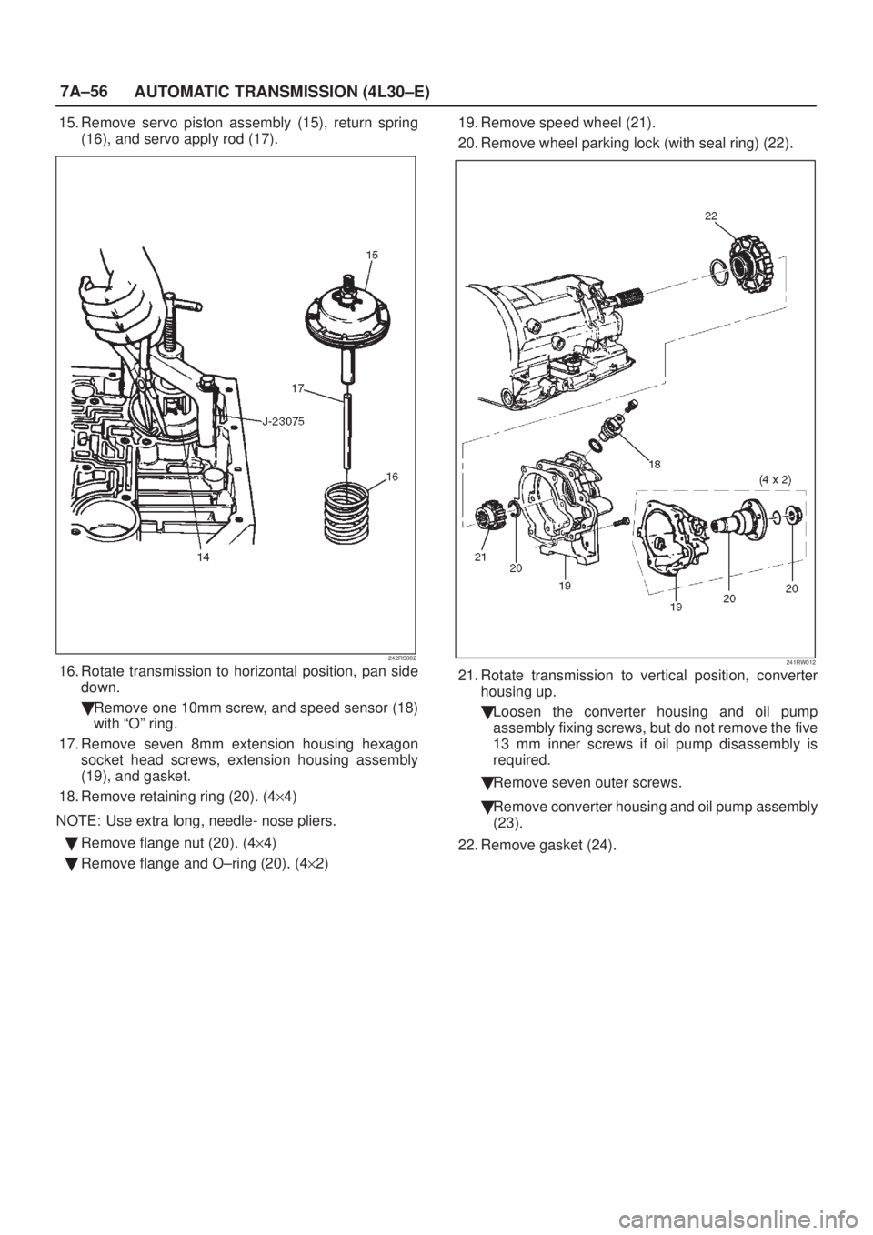
7A±56
AUTOMATIC TRANSMISSION (4L30±E)
15. Remove servo piston assembly (15), return spring
(16), and servo apply rod (17).
242RS002
16. Rotate transmission to horizontal position, pan side
down.
�Remove one 10mm screw, and speed sensor (18)
with ªOº ring.
17. Remove seven 8mm extension housing hexagon
socket head screws, extension housing assembly
(19), and gasket.
18. Remove retaining ring (20). (4y4)
NOTE: Use extra long, needle- nose pliers.
�Remove flange nut (20). (4y4)
�Remove flange and O±ring (20). (4y2)19. Remove speed wheel (21).
20. Remove wheel parking lock (with seal ring) (22).241RW012
21. Rotate transmission to vertical position, converter
housing up.
�Loosen the converter housing and oil pump
assembly fixing screws, but do not remove the five
13 mm inner screws if oil pump disassembly is
required.
�Remove seven outer screws.
�Remove converter housing and oil pump assembly
(23).
22. Remove gasket (24).

3. Gently pull on the connector to check that it is
securely latched.
141RY00006
8. Disconnect transmission harness connector and clip.
Connector : Adapter case")

12. Install harness heat protector.
Torque: 6 Nwm (52 lb in)
815RW002
13. Connect transmission harness connector and clip.
Connector : Adapter case, mode switch")

Speed Sensor (Extension Assembly)
Removal
1. Raise the vehicle and support on jack stands.
2. Disconnect battery ground cable.
3. Disconnect speed sensor harne")