Page 752 of 2100
5C±72
POWER±ASSISTED BRAKE SYSTEM
Front Caliper Brake Hose
Front Caliper Brake Hose and
Associated Parts
352RW001
Legend
(1) Bolt and Gasket
(2) Clip
(3) Hose
(4) Brake Pipe
Removal
1. Raise the vehicle and support it with suitable safety
stands.
2. Remove the wheel and tire assembly.
3. Clean dirt, grease, and other foreign material off the
hose fittings at both ends.
4. Disconnect brake pipe.
5. Remove clip.
6. Remove bolt and gasket.
7. Remove hose.
Installation
To install, follow the removal steps in the reverse order,
noting the following points.
1. Tighten the brake pipes to the specified torque
Torque: 16 N´m (12 lb ft)
2. Tighten the bolt to the specified torque.
Torque: 35 N´m (26 lb ft)
NOTE: Always use new gaskets and be sure to put the
hooked edge of the flexible hose end into the anti±rotation
cavity.
After installing the brake hoses, bleed the brakes as
described in this section.
Page 753 of 2100
5C±73 POWER±ASSISTED BRAKE SYSTEM
Rear Axle Brake Hose
Rear Axle Brake Hose and Associated
Parts
352RW002
Legend
(1) Brake Pipe
(2) Clip
(3) Bolt
(4) Brake Pipe
(5) Hose
Removal
1. Raise the vehicle and support it with suitable safety
stands.
2. Remove wheel and tire assembly.
3. Clean dirt, grease, and other foreign material off the
hose fittings at both ends.
4. Disconnect brake pipe.
5. Remove clip.
6. Remove brake pipe.
7. Remove bolt.
8. Remove hose.
Installation
To install, follow the removal steps in the reverse order,
noting the following points.
1. Tighten the brake pipes to the specified torque
Torque: 16 N´m (12 lb ft)
2. Tighten the bolt to the specified torque.
Torque: 15 N´m (11 lb ft)
After installing the brake hoses, bleed the brakes as
described in this section.
Page 755 of 2100

5C±75 POWER±ASSISTED BRAKE SYSTEM
P & B (Proportioning and Bypass) Valve
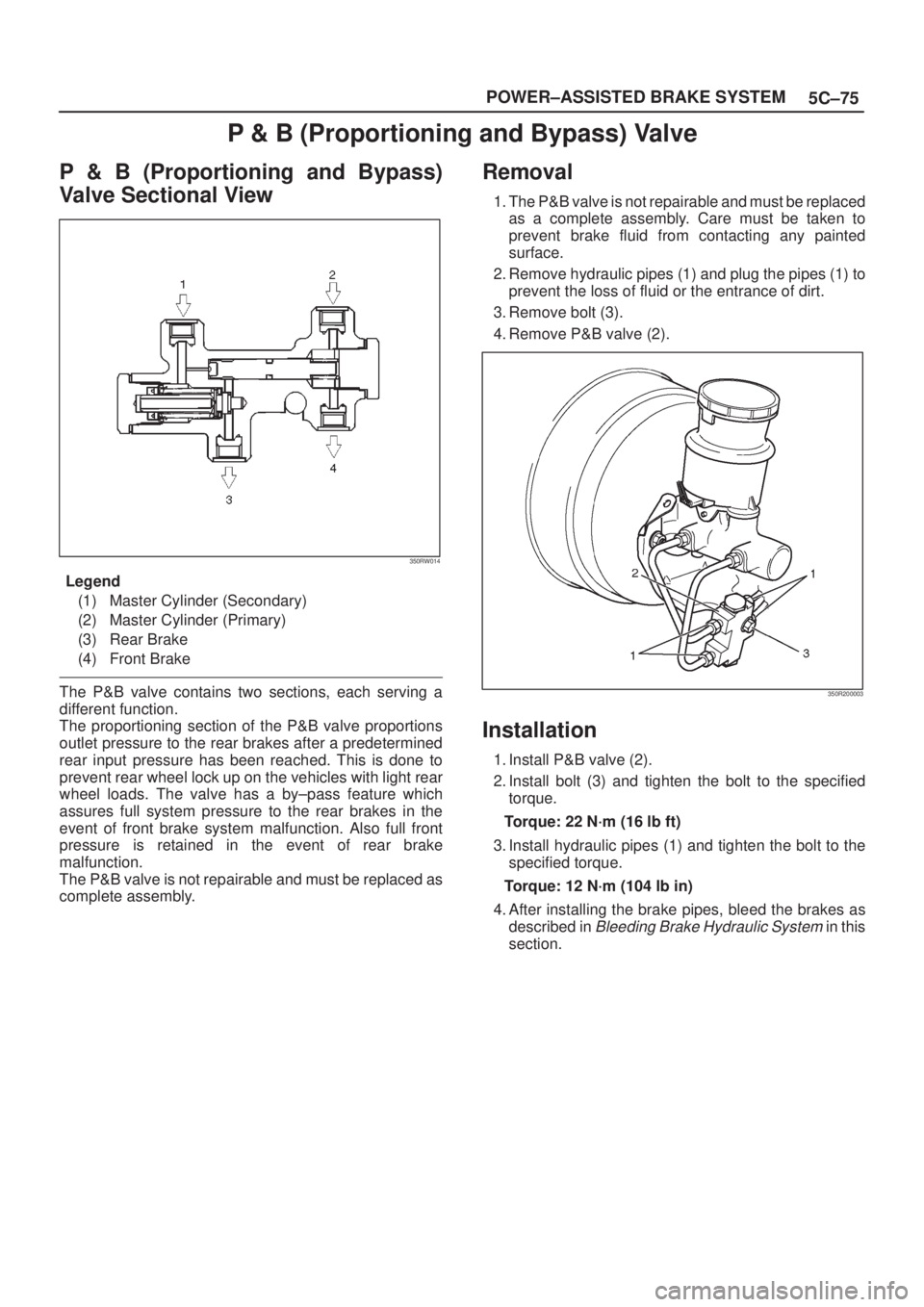
P & B (Proportioning and Bypass)
Valve Sectional View
350RW014
Legend
(1) Master Cylinder (Secondary)
(2) Master Cylinder (Primary)
(3) Rear Brake
(4) Front Brake
The P&B valve contains two sections, each serving a
different function.
The proportioning section of the P&B valve proportions
outlet pressure to the rear brakes after a predetermined
rear input pressure has been reached. This is done to
prevent rear wheel lock up on the vehicles with light rear
wheel loads. The valve has a by±pass feature which
assures full system pressure to the rear brakes in the
event of front brake system malfunction. Also full front
pressure is retained in the event of rear brake
malfunction.
The P&B valve is not repairable and must be replaced as
complete assembly.
Removal
1. The P&B valve is not repairable and must be replaced
as a complete assembly. Care must be taken to
prevent brake fluid from contacting any painted
surface.
2. Remove hydraulic pipes (1) and plug the pipes (1) to
prevent the loss of fluid or the entrance of dirt.
3. Remove bolt (3).
4. Remove P&B valve (2).
350R200003
Installation
1. Install P&B valve (2).
2. Install bolt (3) and tighten the bolt to the specified
torque.
Torque: 22 N´m (16 lb ft)
3. Install hydraulic pipes (1) and tighten the bolt to the
specified torque.
Torque: 12 N´m (104 lb in)
4. After installing the brake pipes, bleed the brakes as
described in
Bleeding Brake Hydraulic System in this
section.
Page 758 of 2100

5C±78
POWER±ASSISTED BRAKE SYSTEM
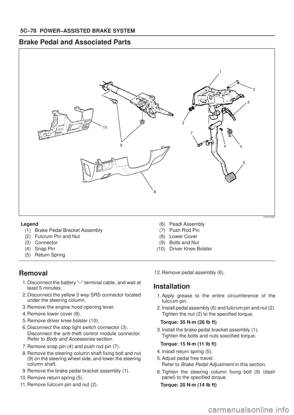
Brake Pedal and Associated Parts
310RY00006
Legend
(1) Brake Pedal Bracket Assembly
(2) Fulcrum Pin and Nut
(3) Connector
(4) Snap Pin
(5) Return Spring(6) Peadl Assembly
(7) Push Rod Pin
(8) Lower Cover
(9) Bolts and Nut
(10) Driver Knee Bolster
Removal
1. Disconnect the battery ª±º terminal cable, and wait at
least 5 minutes.
2. Disconnect the yellow 3 way SRS connector located
under the steering column.
3. Remove the engine hood opening lever.
4. Remove lower cover (8).
5. Remove driver knee bolster (10).
6. Disconnect the stop light switch connector (3).
Disconnect the anti-theft control module connector.
Refer to
Body and Accessories section.
7. Remove snap pin (4) and push rod pin (7).
8. Remove the steering column shaft fixing bolt and nut
(9) on the steering wheel side, and lower the steering
column shaft.
9. Remove the brake pedal bracket assembly (1).
10. Remove return spring (5).
11. Remove fulcrum pin and nut (2).12. Remove pedal assembly (6).
Installation
1. Apply grease to the entire circumference of the
fulcrum pin.
2. Install pedal assembly (6) and fulcrum pin and nut (2).
Tighten the nut (2) to the specified torque.
Torque: 35 N´m (26 lb ft)
3. Install the brake pedal bracket assembly (1).
Tighten the bolts and nuts soecified torque.
Torque: 15 N´m (11 lb ft)
4. Install return spring (5).
5. Adjust pedal free travel.
Refer to
Brake Pedal Adjustment in this section.
6. Tighten the steering column fixing bolt (9) (dash
panel) to the specified torque.
Torque: 20 N´m (14 lb ft)
Page 772 of 2100
5C±92
POWER±ASSISTED BRAKE SYSTEM
3. Carefyully use adjustable pliers to bottom the piston
into the caliper bore. Do not pull or twist the flexible
hose or damage will occur.
Install caliper assembly.
Set caliper assembly in place.
4. Install lock bolt (5) and tighten the bolt to the specified
torque.
Torque: 45 N´m (33 lb ft)
302R200008
5. Install wheel and tire assembly, refer to Wheels and
Tires System
in Section 3E.
6. Pump the brake pedal several times to make sure that
the pedal is firm. Check the brake fluid level in the
reservoir after pumping the brakes.
Page 777 of 2100
5C±97 POWER±ASSISTED BRAKE SYSTEM
4. Install caliper assembly.
5. Install pin bolt (8) and tighten the bolt to the specified
torque.
Torque: 45 N´m (33 lb ft)
302R200010
6. Install brake flexible hose, always use new gaskets
and be sure to put the hooked edge of the flexible
hose end into the anti±rotation cavity then tighten the
I±bolt (9) to the specified torque.
Torque: 35 N´m (26 lb ft)
302R200021
7. Install wheel and tire assembly, referring to Wheels
and Tires System
in Section 3E.
8. Bleed brakes. Refer to
Hydraulic Brakes in this
section.
Page 783 of 2100
5C±103 POWER±ASSISTED BRAKE SYSTEM
306RW005
3. Carefyully use adjustable pliers to bottom the piston
into the caliper bore. Do not pull or twist the flex hose
or damage will occur.
302RS008
4. Install lock bolt (5) and tighten the bolt to the specified
torque.
Torque: 44 N´m (32 lb ft)
306R200003
5. Install wheel and tire assembly, referring to Wheels
and Tires System
in Section 3E.
6. Pump the brake pedal several times to make sure that
the pedal is firm. Check the brake fluid level in the
reservoir after pumping the brakes.
Page 795 of 2100

5C±115 POWER±ASSISTED BRAKE SYSTEM
Machining The Drum
If a drum is to be machined, only enough metal should be
removed to obtain a true, smooth braking surface. If a
drum does not clean-up when machined to a maximum
diameter, it must be replaced. Removal of more metal willaffect dissipation of heat and may cause distortion of the
drum.
After refinishing, replace any drum that exceeds a
maximum inside diameter of 296.5 mm (11.673 in). Do
not use a brake drum that is not within the specification.
Maximum inside diameter: 296.5 mm (11.673 in)
Wheel Cylinder Assembly (4y2 Model)
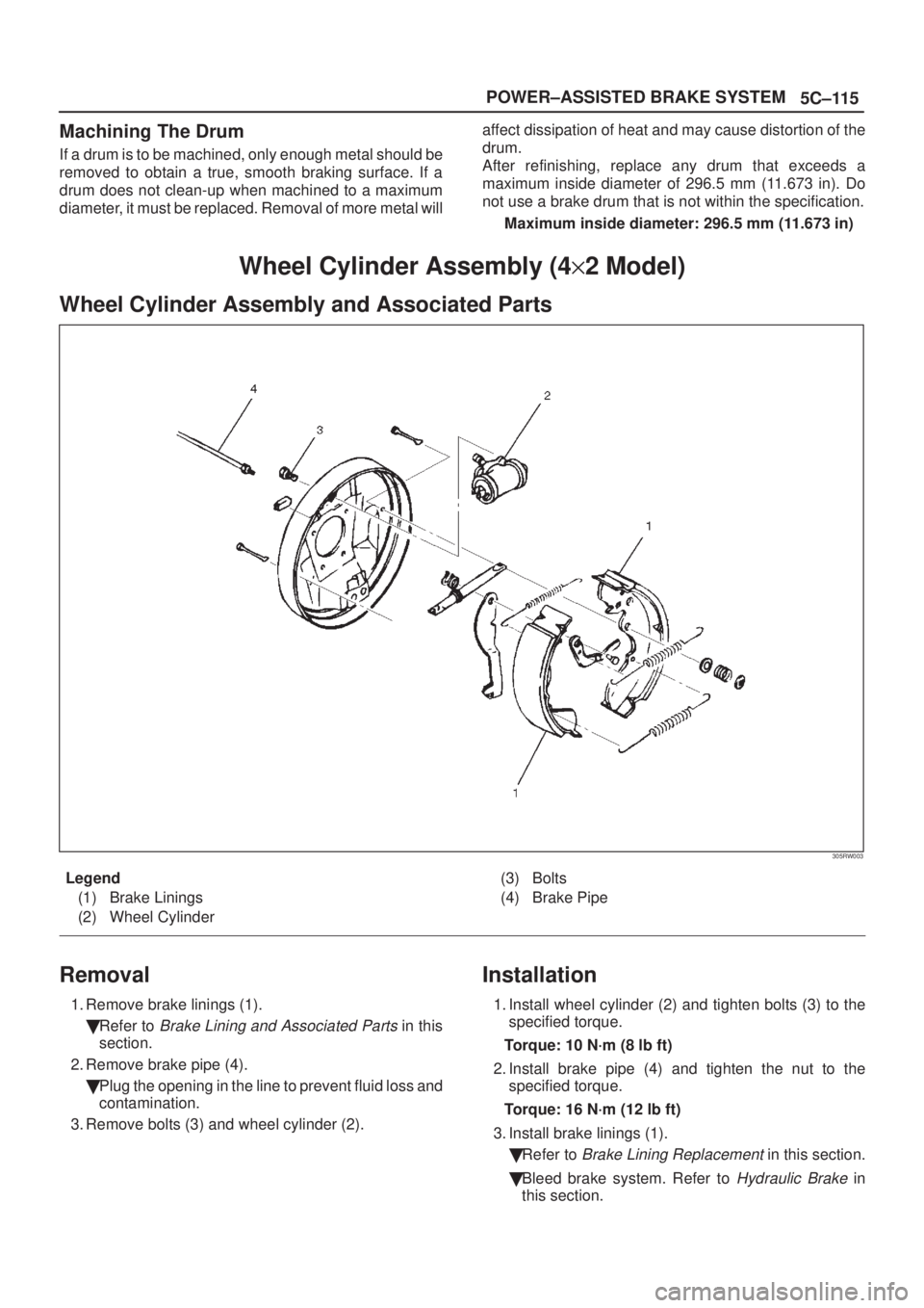
Wheel Cylinder Assembly and Associated Parts
305RW003
Legend
(1) Brake Linings
(2) Wheel Cylinder(3) Bolts
(4) Brake Pipe
Removal
1. Remove brake linings (1).
�Refer to
Brake Lining and Associated Parts in this
section.
2. Remove brake pipe (4).
�Plug the opening in the line to prevent fluid loss and
contamination.
3. Remove bolts (3) and wheel cylinder (2).
Installation
1. Install wheel cylinder (2) and tighten bolts (3) to the
specified torque.
Torque: 10 N´m (8 lb ft)
2. Install brake pipe (4) and tighten the nut to the
specified torque.
Torque: 16 N´m (12 lb ft)
3. Install brake linings (1).
�Refer to
Brake Lining Replacement in this section.
�Bleed brake system. Refer to
Hydraulic Brake in
this section.