Page 1838 of 2100
8D±3
WIRING SYSTEM
Relay / Fuse Box (Instrument Panel)
D08RY00529
Legend
(1) Fuse/Relay Box
(2) Diode
(3) Diode
(4) Tail Relay
(5) Not Used
(6) ACC Socket Relay
(7) Power Window Relay
(8) Not Used
(9) Rear Defogger Relay
(10) Fuse ACC Socket (15A)
(11) Fuse Audio (+B) (15A)
(12) Fuse Starter (10A)
(13) Fuse Tail (15A)
(14) Fuse Room Lamp (10A)
(15) Fuse Stop Lamp (15A)
(16) Fuse Door Lock (20A)
(17) Fuse Mirror Defogger (10A)(18) Fuse Rear Defogger (15A)
(19) Fuse Rear Defogger (15A)
(20) Fuse Meter (15A)
(21) Fuse ENG. (15A)
(22) Fuse IG. Coil (15A)
(23) Fuse Back Up (15A)
(24) Fuse ELEC. IG. (15A)
(25) Fuse RR Wiper (10A)
(26) Fuse FRT Wiper (20A)
(27) Fuse Audio (ACC) (10A)
(28) Fuse Cigar Lighter (15A)
(29) Fuse Anti-theft (10A)
(30) Fuse SRS (10A)
(31) Fuse (Not Used)
(32) Circuit Breaker Power Window (30A)
(33) Spare Fuse (20A)
(34) Spare Fuse (15A)
(35) Spare Fuse (10A)
Page 1854 of 2100
8D±19
WIRING SYSTEM
Door Mirror
D08R200010
Page 1915 of 2100
8F±39 BODY STRUCTURE
Front Window Regulator, Glass and Glass Run
Parts Location
635R200012
Legend
(1) Glass
(2) Glass Run
(3) Door Mirror Assembly
(4) Door Mirror Cover
(5) Tweeter
(6) Speaker Spacer
(7) Speaker Assembly
(8) Inner Waist Seal
(9) Door Trim Panel
(10) Power Window Switch
(11) Inside Lock Bracket(12) Inside Handle
(13) Pull Box
(14) Courtesy Light
(15) Pull Box Bracket
(16) Waterproof Sheet
(17) Front Door Panel
(18) Door Lock Assembly
(19) Door Lock Cylinder
(20) Outside Handle
(21) Window Regulator
(22) Outer Waist Seal
Page 1916 of 2100
8F±40BODY STRUCTURE
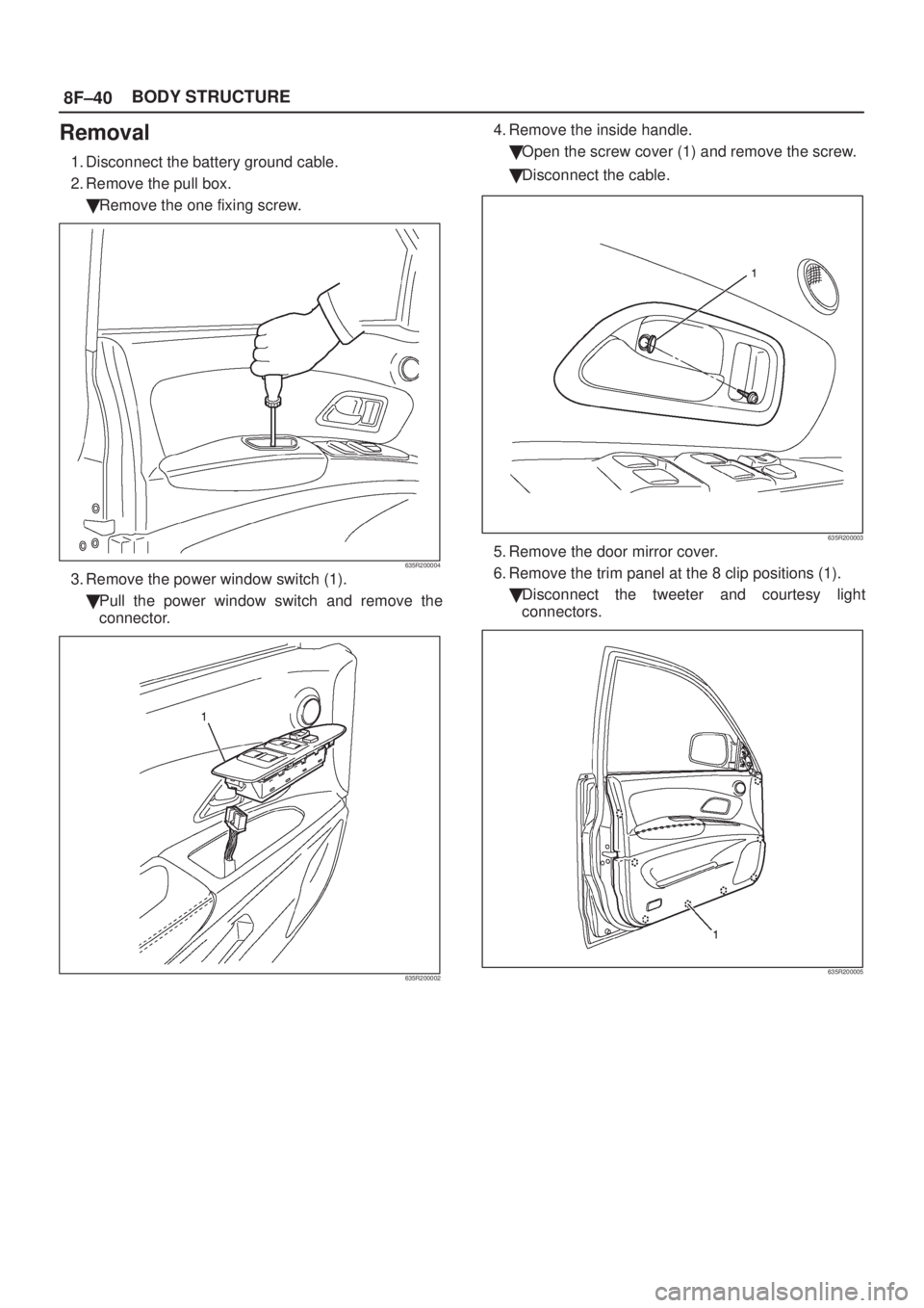
Removal
1. Disconnect the battery ground cable.
2. Remove the pull box.
�Remove the one fixing screw.
635R200004
3. Remove the power window switch (1).
�Pull the power window switch and remove the
connector.
635R200002
4. Remove the inside handle.
�Open the screw cover (1) and remove the screw.
�Disconnect the cable.
635R200003
5. Remove the door mirror cover.
6. Remove the trim panel at the 8 clip positions (1).
�Disconnect the tweeter and courtesy light
connectors.
635R200005
Page 1927 of 2100
8F±51 BODY STRUCTURE
Windshield
Parts Location
607R200003
Legend
(1) Windshield Wiper Arm
(2) Windshield Upper Molding
(3) Windshield(4) Windshield Side Molding
(5) Windshield Support
(6) Front Cowl Cover
(7) Hood Rear Seal
Removal
1. Disconnect the battery ground cable.
2. Remove the front pillar trim cover.
�Turn up the finisher and pry the trim cover clips free
from the body panel.
3. Remove the sunvisors and sunvisor holders.
�Refer to
Headlining in Exterior/Interior Trim section.
4. Remove the interior mirror.
�Refer to
Interior Mirror Assembly in Exterior/Interior
Trim section.
5. Remove the windshield wiper arm.
�Refer to
Windshield Wiper Arm/Blade in
Wiper/Washer System section.
6. Remove the windshield side molding.
�Pull the molding out from drip rail.
7. Remove the front cowl cover.
Page 1952 of 2100
8H±2SECURITY AND LOCKS
Front Door Lock Assembly
Front Door Lock Assembly and Associated Parts
635R200008
Legend
(1) Door Mirror Cover
(2) Power Window Switch
(3) Door Trim Panel
(4) Inside Lock Bracket
(5) Inside Handle(6) Pull Box
(7) Pull Box Bracket
(8) Waterproof Sheet
(9) Door Lock Assembly
(10) Door Lock Cylinder
(11) Outside Handle
Removal
1. Disconnect the battery ground cable.
2. Remove the pull box.
�Remove the one fixing screw.
635R200004
Page 1953 of 2100
SECURITY AND LOCKS8H±3
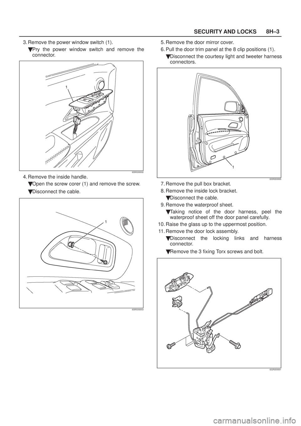
3. Remove the power window switch (1).
�Pry the power window switch and remove the
connector.
635R200002
4. Remove the inside handle.
�Open the screw corer (1) and remove the screw.
�Disconnect the cable.
635R200003
5. Remove the door mirror cover.
6. Pull the door trim panel at the 8 clip positions (1).
�Disconnect the courtesy light and tweeter harness
connectors.
635R200005
7. Remove the pull box bracket.
8. Remove the inside lock bracket.
�Disconnect the cable.
9. Remove the waterproof sheet.
�Taking notice of the door harness, peel the
waterproof sheet off the door panel carefully.
10. Raise the glass up to the uppermost position.
11. Remove the door lock assembly.
�Disconnect the locking links and harness
connector.
�Remove the 3 fixing Torx screws and bolt.
632R200001
Page 1955 of 2100
 Door Mirror Cover
(2) Power Window Switch
(3) Door Trim Panel
(4) Inside Lock Bracket
(5) I")
SECURITY AND LOCKS8H±5
Front Outside Handle
Front Outside Handle and Associated Parts
635R200008
Legend
(1) Door Mirror Cover
(2) Power Window Switch
(3) Door Trim Panel
(4) Inside Lock Bracket
(5) Inside Handle(6) Pull Box
(7) Pull Box Bracket
(8) Waterproof Sheet
(9) Door Lock Assembly
(10) Door Locking Cylinder
(11) Outside Handle
Removal
1. Disconnect the battery ground cable.
2. Remove the door trim panel.
�Refer to
Front Door Lock Assembly in this section.
3. Remove the waterproof sheet.
�Taking notice of the door harness, peel the
waterproof sheet off the door panel carefully.
4. Disconnect the locking links and remove the outside
handle.
5. Remove the fixing clip to remove the door lock
cylinder.
Installation
To install, follow the removal steps in the reverse order,
noting the following points:
1. Be sure to install the door lock cylinder at a specified
angle to the outside handle.
2. Check for smooth outside handle and lock cylinder
operation.
3. Tighten the outside handle fixing bolts to the specified
torque.
Torque 7 N´m (61 Ib in)

D08RY00529
Legend
(1) Fuse/Relay Box
(2) Diode
(3) Diode
(4) Tail Relay
(5) Not Used
(6) ACC Socket Relay
(7) Power Window Relay
(8) Not Used
(9")

 Glass
(2) Glass Run
(3) Door Mirror Assembly
(4) Door Mirror Cover
(5) Tweeter
(6) Speaker Spacer")
 Windshield Wiper Arm
(2) Windshield Upper Molding
(3) Windshield(4) Windshield Side Molding
(5) Windshield Support
(6) Front Cowl")
 Door Mirror Cover
(2) Power Window Switch
(3) Door Trim Panel
(4) Inside Lock Brack")