2002 DODGE RAM RACK
[x] Cancel search: RACKPage 30 of 2255
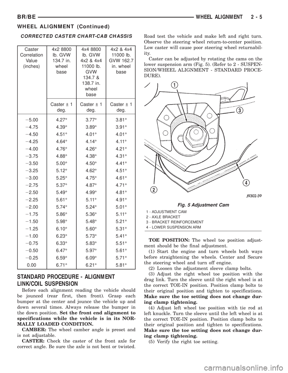
CORRECTED CASTER CHART-CAB CHASSIS
Caster
Correlation
Value
(inches)4x2 8800
lb. GVW
134.7 in.
wheel
base4x4 8800
lb. GVW
4x2 & 4x4
11000 lb.
GVW
134.7 &
138.7 in.
wheel
base4x2 & 4x4
11000 lb.
GVW 162.7
in. wheel
base
Caster 1
deg.Caster 1
deg.Caster 1
deg.
25.00 4.27É 3.77É 3.81É
24.75 4.39É 3.89É 3.91É
24.50 4.51É 4.01É 4.01É
24.25 4.64É 4.14É 4.11É
24.00 4.76É 4.26É 4.21É
23.75 4.88É 4.38É 4.31É
23.50 5.00É 4.50É 4.41É
23.25 5.12É 4.62É 4.51É
23.00 5.25É 4.75É 4.61É
22.75 5.37É 4.87É 4.71É
22.50 5.49É 4.99É 4.81É
22.25 5.61É 5.11É 4.91É
22.00 5.74É 5.24É 5.01É
21.75 5.86É 5.36É 5.11É
21.50 5.98É 5.48É 5.21É
21.25 6.10É 5.60É 5.31É
21.00 6.23É 5.73É 5.41É
20.75 6.33É 5.83É 5.51É
20.50 6.47É 5.97É 5.61É
20.25 6.59É 6.09É 5.71É
0.00 6.71É 6.21É 5.81É
STANDARD PROCEDURE - ALIGNMENT
LINK/COIL SUSPENSION
Before each alignment reading the vehicle should
be jounced (rear first, then front). Grasp each
bumper at the center and jounce the vehicle up and
down several times. Always release the bumper in
the down position.Set the front end alignment to
specifications while the vehicle is in its NOR-
MALLY LOADED CONDITION.
CAMBER:The wheel camber angle is preset and
is not adjustable.
CASTER:Check the caster of the front axle for
correct angle. Be sure the axle is not bent or twisted.Road test the vehicle and make left and right turn.
Observe the steering wheel return-to-center position.
Low caster will cause poor steering wheel returnabil-
ity.
Caster can be adjusted by rotating the cams on the
lower suspension arm (Fig. 5). (Refer to 2 - SUSPEN-
SION/WHEEL ALIGNMENT - STANDARD PROCE-
DURE).
TOE POSITION:The wheel toe position adjust-
ment should be the final adjustment.
(1) Start the engine and turn wheels both ways
before straightening the wheels. Center and Secure
the steering wheel and turn off engine.
(2) Loosen the adjustment sleeve clamp bolts.
(3) Adjust the right wheel toe position with the
drag link. Turn the sleeve until the right wheel is at
the correct TOE-IN position. Position clamp bolts to
their original position and tighten to specifications.
Make sure the toe setting does not change dur-
ing clamp tightening.
(4) Adjust left wheel toe position with tie rod at
left knuckle. Turn the sleeve until the left wheel is at
the correct TOE-IN position. Position clamp bolts to
their original position and tighten to specifications.
Make sure the toe setting does not change dur-
ing clamp tightening.
(5) Verify the right toe setting.
Fig. 5 Adjustment Cam
1 - ADJUSTMENT CAM
2 - AXLE BRACKET
3 - BRACKET REINFORCEMENT
4 - LOWER SUSPENSION ARM
BR/BEWHEEL ALIGNMENT 2 - 5
WHEEL ALIGNMENT (Continued)
Page 33 of 2255
CAUTION: Suspension components with rubber/ure-
thane bushings (except stabilizer bar) should be
tightened with the vehicle at normal ride height. It is
important to have the springs supporting the weight
of the vehicle when the fasteners are torqued. If
springs are not at their normal ride position, vehicle
ride comfort could be affected and premature bush-
ing wear may occur.
DESCRIPTION
The upper suspension arm bolts on frame brackets
through the arm pivot shaft. The frame brackets
have slotted holes which allow the arms to be
adjusted for caster and camber. Pivot shaft bushings
are not replaceable.
The lower suspension arms bolt to the lower frame
brackets and pivot through bushings, these bushings
are not replaceable.
The suspension arms have lube for life riveted ball
studs.
SPECIFICATIONS
TORQUE CHART
TORQUE SPECIFICATIONS
DESCRIPTION N´m Ft. Lbs. In. Lbs.
Shock Absorber
Upper Nut54 40 Ð
Shock Absorber
Lower Bolt142 105 Ð
Lower Suspension Arm
Frame Nuts169 125 Ð
Lower Suspension Arm
Ball Joint Nut149 110 Ð
Upper Suspension Arm
Pivot Bar Nuts169 125 Ð
Upper Suspension Arm
Ball Joint Nut81 60 Ð
Stabilizer Bar
Clamp Bolt54 40 Ð
Stabilizer Bar
Link Nuts37 27 Ð
Hub Bearing
2500/3500 Nut380 280 Ð
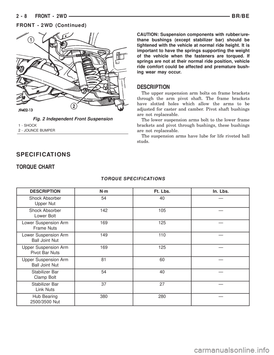
Fig. 2 Independent Front Suspension
1 - SHOCK
2 - JOUNCE BUMPER
2 - 8 FRONT - 2WDBR/BE
FRONT - 2WD (Continued)
Page 36 of 2255

²136 N´m (110 ft. lbs.) Install the lower ball joint
cotter pin.
(6) Install the stabilizer bar link on the lower sus-
pension arm. Install the grommet, retainer and nut
and tighten to 37 N´m (27 ft. lbs.).
(7) Install the tie rod end on the steering knuckle
and tighten nut to 108 N´m (80 ft. lbs.). Install cotter
pin.
(8) Install the brake rotor and caliper assembly,
(Refer to 5 - BRAKES/HYDRAULIC/MECHANICAL/
ROTORS - INSTALLATION).
(9) Install the tire and wheel assembly, (Refer to
22 - TIRES/WHEELS/WHEELS - STANDARD PRO-
CEDURE).
(10) Remove the support and lower the vehicle.
(11) Tighten the suspension arm crossmember
nuts to 169 N´m (125 ft. lbs.).
SHOCK
DIAGNOSIS AND TESTING - SHOCK
A knocking or rattling noise from a shock absorber
may be caused by movement between mounting
bushings and metal brackets or attaching compo-
nents. These noises can usually be stopped by tight-
ening the attaching nuts. If the noise persists,
inspect for damaged and worn bushings, and attach-
ing components. Repair as necessary if any of these
conditions exist.
A squeaking noise from the shock absorber may be
caused by the hydraulic valving and may be intermit-
tent. This condition is not repairable and the shock
absorber must be replaced.
The shock absorbers are not refillable or adjust-
able. If a malfunction occurs, the shock absorber
must be replaced. To test a shock absorber, hold it in
an upright position and force the piston in and out of
the cylinder four or five times. The action throughout
each stroke should be smooth and even.
The shock absorber bushings do not require any
type of lubrication. Do not attempt to stop bushing
noise by lubricating them. Grease and mineral oil-
base lubricants will deteriorate the bushing.
REMOVAL
(1) Raise and support vehicle.
(2) Remove shock upper nut and remove retainer
and grommet.
(3) Remove lower mounting bolt from suspension
arm and remove shock (Fig. 5).
INSTALLATION
(1) Extend shock fully, install retainer and grom-
met on top of shock absorber. Check grommets and
retainer for wear.(2) Guide shock up through upper suspension arm
bracket. Install top grommet, retainer and nut.
Tighten nut to 54 N´m (40 ft. lbs.).
(3) Align bottom end of shock into lower suspen-
sion arm and install mounting bolt. Tighten bolt to
142 N´m (105 ft. lbs.).
(4) Remove support and lower vehicle.
SPRING
REMOVAL
(1) Raise and support the vehicle.
(2) Remove the tire and wheel assembly.
(3) Remove the brake caliper assembly and rotor,
(Refer to 5 - BRAKES/HYDRAULIC/MECHANICAL/
ROTORS - REMOVAL).
(4) Remove the cotter pin and nut from the tie rod.
Remove the tie rod end from the steering knuckle
with Puller C-3894-A.
(5) Remove the stabilizer bar link from the lower
suspension arm.
(6) Support the lower suspension arm outboard
end with a jack. Place a jack under the arm in front
of the shock mount.
(7) Remove the cotter pin and nut from the lower
ball joint. Separate the ball joint with Remover
C-4150A.
(8) Remove the lower shock bolt from the suspen-
sion arm.
(9) Lower the jack and suspension arm until
spring tension is relieved. Remove spring and rubber
isolator (Fig. 6).
Fig. 5 Shock
1 - SHOCK
2 - JOUNCE BUMPER
BR/BEFRONT - 2WD 2 - 11
LOWER CONTROL ARM (Continued)
Page 38 of 2255
UPPER CONTROL ARM
REMOVAL
(1) Raise and support vehicle.
(2) Remove tire and wheel assembly.
(3) Support lower suspension arm at outboard end
with jack stand.
(4) Remove upper ball joint cotter pin and nut.
(5) Separate ball joint from knuckle with remover
MB-990635.
(6) Remove pivot bar bolts from upper suspension
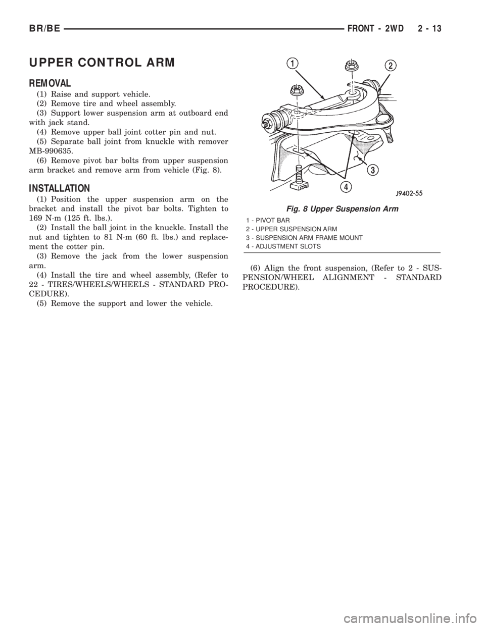
arm bracket and remove arm from vehicle (Fig. 8).
INSTALLATION
(1) Position the upper suspension arm on the
bracket and install the pivot bar bolts. Tighten to
169 N´m (125 ft. lbs.).
(2) Install the ball joint in the knuckle. Install the
nut and tighten to 81 N´m (60 ft. lbs.) and replace-
ment the cotter pin.
(3) Remove the jack from the lower suspension
arm.
(4) Install the tire and wheel assembly, (Refer to
22 - TIRES/WHEELS/WHEELS - STANDARD PRO-
CEDURE).
(5) Remove the support and lower the vehicle.(6) Align the front suspension, (Refer to 2 - SUS-
PENSION/WHEEL ALIGNMENT - STANDARD
PROCEDURE).
Fig. 8 Upper Suspension Arm
1 - PIVOT BAR
2 - UPPER SUSPENSION ARM
3 - SUSPENSION ARM FRAME MOUNT
4 - ADJUSTMENT SLOTS
BR/BEFRONT - 2WD 2 - 13
Page 39 of 2255
FRONT - 4WD
TABLE OF CONTENTS
page page
FRONT - 4WD
DESCRIPTION
DESCRIPTION........................14
DESCRIPTION........................15
SPECIFICATIONS
TORQUE CHART......................15
SPECIAL TOOLS
LINK/COIL SUSPENSION...............16
HUB / BEARING
REMOVAL.............................16
INSTALLATION.........................17
KNUCKLE
REMOVAL.............................19
INSTALLATION.........................19
UPPER CONTROL ARM
REMOVAL.............................19
INSTALLATION.........................19
UPPER BALL JOINT
REMOVAL - DANA 44 & 60................19
INSTALLATION
INSTALLATION - DANA 44 AXLE..........20
INSTALLATION - DANA 60 AXLE..........20
LOWER CONTROL ARM
REMOVAL.............................20INSTALLATION.........................20
LOWER BALL JOINT
REMOVAL
REMOVAL - DANA 44 AXLE..............21
REMOVAL - DANA 60 AXLE..............21
INSTALLATION
INSTALLATION - DANA 44 AXLE..........21
INSTALLATION - DANA 60 AXLE..........22
SHOCK
DIAGNOSIS AND TESTING - SHOCK........22
REMOVAL.............................22
INSTALLATION.........................22
SPRING
REMOVAL.............................23
INSTALLATION.........................23
STABILIZER BAR
REMOVAL.............................23
INSTALLATION.........................23
TRACK BAR
DIAGNOSIS AND TESTING - TRACK BAR....24
REMOVAL.............................24
INSTALLATION.........................24
FRONT - 4WD
DESCRIPTION
DESCRIPTION
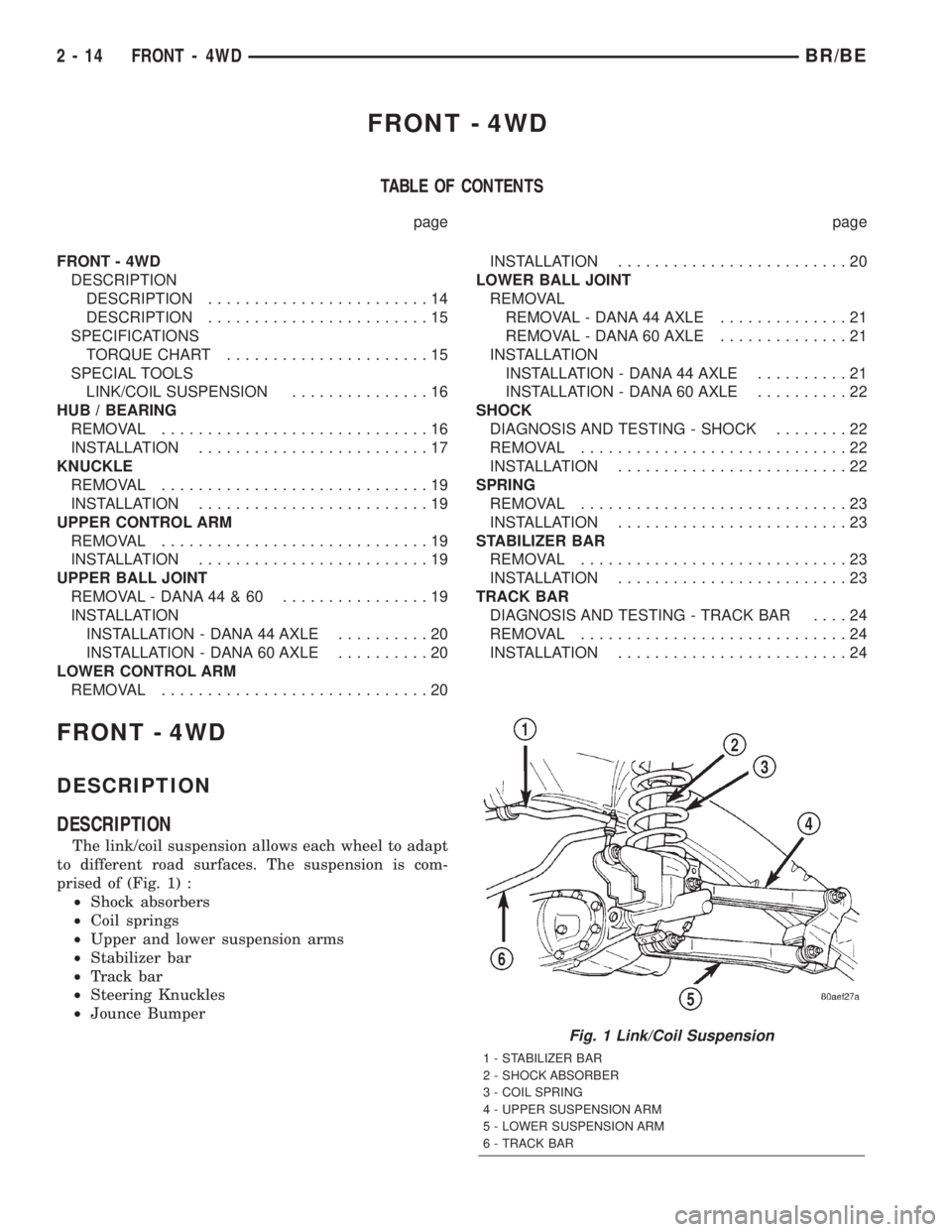
The link/coil suspension allows each wheel to adapt
to different road surfaces. The suspension is com-
prised of (Fig. 1) :
²Shock absorbers
²Coil springs
²Upper and lower suspension arms
²Stabilizer bar
²Track bar
²Steering Knuckles
²Jounce Bumper
Fig. 1 Link/Coil Suspension
1 - STABILIZER BAR
2 - SHOCK ABSORBER
3 - COIL SPRING
4 - UPPER SUSPENSION ARM
5 - LOWER SUSPENSION ARM
6 - TRACK BAR
2 - 14 FRONT - 4WDBR/BE
Page 40 of 2255
CAUTION: Components attached with a nut and cot-
ter pin must be torqued to specification. Then if the
slot in the nut does not line up with the cotter pin
hole, tighten nut until it is aligned. Never loosen the
nut to align the cotter pin hole.
CAUTION: Suspension components with rubber
bushings (except stabilizer bar) should be tightened
with the vehicle at normal height. It is important to
have the springs supporting the weight of the vehi-
cle when the fasteners are torqued. If springs arenot at their normal ride position, vehicle ride com-
fort could be affected and premature bushing wear
may occur.
DESCRIPTION
The upper and lower suspension arms use bush-
ings to isolate road noise. The suspension arms are
bolted to the frame and axle through the rubber
bushings. The lower suspension arm uses cam bolts
at the axle to allow for caster and pinion angle
adjustment.
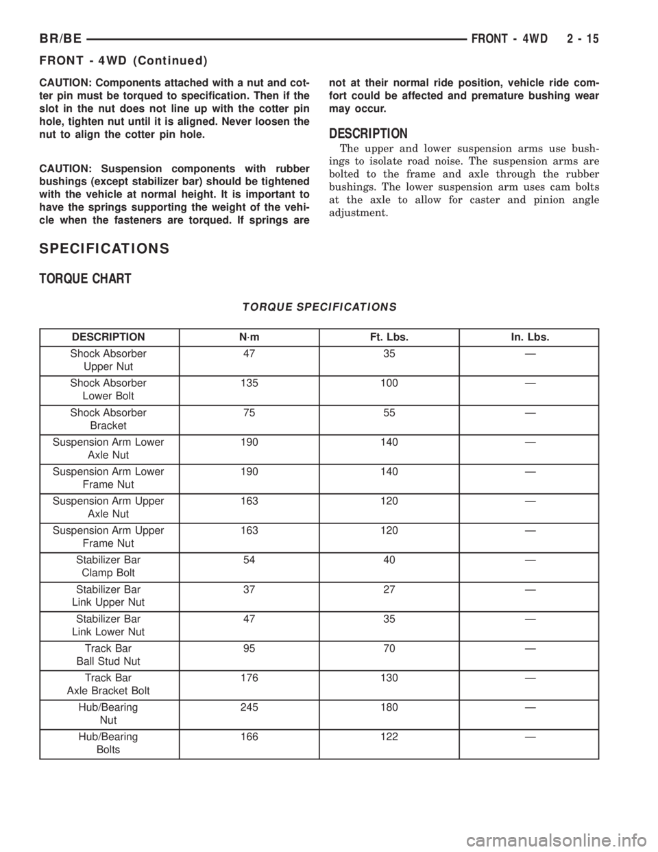
SPECIFICATIONS
TORQUE CHART
TORQUE SPECIFICATIONS
DESCRIPTION N´m Ft. Lbs. In. Lbs.
Shock Absorber
Upper Nut47 35 Ð
Shock Absorber
Lower Bolt135 100 Ð
Shock Absorber
Bracket75 55 Ð
Suspension Arm Lower
Axle Nut190 140 Ð
Suspension Arm Lower
Frame Nut190 140 Ð
Suspension Arm Upper
Axle Nut163 120 Ð
Suspension Arm Upper
Frame Nut163 120 Ð
Stabilizer Bar
Clamp Bolt54 40 Ð
Stabilizer Bar
Link Upper Nut37 27 Ð
Stabilizer Bar
Link Lower Nut47 35 Ð
Track Bar
Ball Stud Nut95 70 Ð
Track Bar
Axle Bracket Bolt176 130 Ð
Hub/Bearing
Nut245 180 Ð
Hub/Bearing
Bolts166 122 Ð
BR/BEFRONT - 4WD 2 - 15
FRONT - 4WD (Continued)
Page 44 of 2255

KNUCKLE
REMOVAL
(1) Remove hub bearing and axle shaft.
(2) Remove tie-rod or drag link end from the steer-
ing knuckle arm.
(3) Remove the ABS sensor wire and bracket from
knuckle. Refer to Brakes, for proper procedures.
(4) Remove the cotter pin from the upper ball stud
nut. Remove the upper and lower ball stud nuts.
(5) Strike the steering knuckle with a brass ham-
mer to loosen.
(6) Remove knuckle from axle tube yokes.
INSTALLATION
(1) Position the steering knuckle on the ball studs.
(2) Install and tighten lower ball stud nut to 47
N´m (35 ft. lbs.) torque. Do not install cotter pin at
this time.
(3) Install and tighten upper ball stud nut to 94
N´m (70 ft. lbs.) torque. Advance nut to next slot to
line up hole and install new cotter pin.
(4) Retorque lower ball stud nut to 190±217 N´m
(140±160 ft. lbs.) torque. Advance nut to next slot to
line up hole and install new cotter pin.
(5) Install the hub bearing and axle shaft.
(6) Install tie-rod or drag link end onto the steer-
ing knuckle arm.
(7) Install the ABS sensor wire and bracket to the
knuckle. Refer to Brakes, for proper procedure.
UPPER CONTROL ARM
REMOVAL
(1) Raise and support the vehicle.
(2) Remove the upper suspension arm nut and bolt
at the axle bracket (Fig. 12).
(3) Remove the nut and bolt at the frame rail and
remove the upper suspension arm.
INSTALLATION
(1) Position the upper suspension arm at the axle
and frame rail.
(2) Install the bolts and finger tighten the nuts.
(3) Remove the supports and lower the vehicle.
(4) Tighten nut at the axle bracket to 163 N´m
(120 ft. lbs.). Tighten nut at frame bracket to 163
N´m (120 ft. lbs.).
UPPER BALL JOINT
REMOVAL - DANA 44 & 60
(1) Position tools as shown to remove upper ball
stud (Fig. 13).
Fig. 12 Upper and Lower Suspension Arm
1 - STABILIZER BAR
2 - SHOCK ABSORBER
3 - COIL SPRING
4 - UPPER SUSPENSION ARM
5 - LOWER SUSPENSION ARM
6 - TRACK BAR
Fig. 13 UPPER BALL JOINT REMOVAL
1 - SPECIAL TOOL C4212-F
2 - SPECIAL TOOL 6761
3 - KNUCKLE
4 - SPECIAL TOOL 8445-3
BR/BEFRONT - 4WD 2 - 19
Page 45 of 2255
INSTALLATION
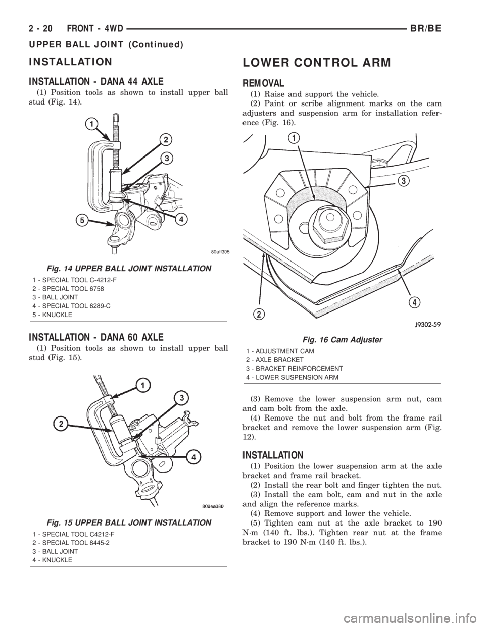
INSTALLATION - DANA 44 AXLE
(1) Position tools as shown to install upper ball
stud (Fig. 14).
INSTALLATION - DANA 60 AXLE
(1) Position tools as shown to install upper ball
stud (Fig. 15).
LOWER CONTROL ARM
REMOVAL
(1) Raise and support the vehicle.
(2) Paint or scribe alignment marks on the cam
adjusters and suspension arm for installation refer-
ence (Fig. 16).
(3) Remove the lower suspension arm nut, cam
and cam bolt from the axle.
(4) Remove the nut and bolt from the frame rail
bracket and remove the lower suspension arm (Fig.
12).
INSTALLATION
(1) Position the lower suspension arm at the axle
bracket and frame rail bracket.
(2) Install the rear bolt and finger tighten the nut.
(3) Install the cam bolt, cam and nut in the axle
and align the reference marks.
(4) Remove support and lower the vehicle.
(5) Tighten cam nut at the axle bracket to 190
N´m (140 ft. lbs.). Tighten rear nut at the frame
bracket to 190 N´m (140 ft. lbs.).
Fig. 14 UPPER BALL JOINT INSTALLATION
1 - SPECIAL TOOL C-4212-F
2 - SPECIAL TOOL 6758
3 - BALL JOINT
4 - SPECIAL TOOL 6289-C
5 - KNUCKLE
Fig. 15 UPPER BALL JOINT INSTALLATION
1 - SPECIAL TOOL C4212-F
2 - SPECIAL TOOL 8445-2
3 - BALL JOINT
4 - KNUCKLE
Fig. 16 Cam Adjuster
1 - ADJUSTMENT CAM
2 - AXLE BRACKET
3 - BRACKET REINFORCEMENT
4 - LOWER SUSPENSION ARM
2 - 20 FRONT - 4WDBR/BE
UPPER BALL JOINT (Continued)