2002 DODGE RAM RACK
[x] Cancel search: RACKPage 166 of 2255

Condition Possible Causes Correction
Loss Of Lubricant 1. Lubricant level too high. 1. Drain lubricant to the correct
level.
2. Worn axle shaft seals. 2. Replace seals.
3. Cracked differential housing. 3. Repair as necessary.
4. Worn pinion seal. 4. Replace seal.
5. Worn/scored yoke. 5. Replace yoke and seal.
6. Axle cover not properly sealed. 6. Remove, clean, and re-seal
cover.
Axle Overheating 1. Lubricant level low. 1. Fill differential to correct level.
2. Improper grade of lubricant. 2. Fill differential with the correct
fluid type and quantity.
3. Bearing pre-loads too high. 3. Re-adjust bearing pre-loads.
4. Insufficient ring gear backlash. 4. Re-adjust ring gear backlash.
Gear Teeth Broke 1. Overloading. 1. Replace gears. Examine other
gears and bearings for possible
damage.
2. Erratic clutch operation. 2. Replace gears and examine the
remaining parts for damage. Avoid
erratic clutch operation.
3. Ice-spotted pavement. 3. Replace gears and examine
remaining parts for damage.
4. Improper adjustments. 4. Replace gears and examine
remaining parts for damage. Ensure
ring gear backlash is correct.
Axle Noise 1. Insufficient lubricant. 1. Fill differential with the correct
fluid type and quantity.
2. Improper ring gear and pinion
adjustment.2. Check ring gear and pinion
contact pattern. Adjust backlash or
pinion depth.
3. Unmatched ring gear and pinion. 3. Replace gears with a matched
ring gear and pinion.
4. Worn teeth on ring gear and/or
pinion.4. Replace ring gear and pinion.
5. Loose pinion bearings. 5. Adjust pinion bearing pre-load.
6. Loose differential bearings. 6. Adjust differential bearing
pre-load.
7. Mis-aligned or sprung ring gear. 7. Measure ring gear run-out.
Replace components as necessary.
8. Loose differential bearing cap
bolts.8. Inspect differential components
and replace as necessary. Ensure
that the bearing caps are torqued
tot he proper specification.
9. Housing not machined properly. 9. Replace housing.
BR/BEREAR AXLE - 286RBI 3 - 111
REAR AXLE - 286RBI (Continued)
Page 167 of 2255

REMOVAL
(1) Raise and support the vehicle.
(2) Position a suitable lifting device under the
axle.
(3) Secure axle to device.
(4) Remove the wheels and tires.
(5) Remove the RWAL sensor from the differential
housing, if necessary.
(6) Disconnect the brake hose at the axle junction
block.
(7) Disconnect the parking brake cables and cable
brackets.
(8)
Disconnect the vent hose from the axle shaft tube.
(9) Mark the propeller shaft and companion flange
for installation alignment reference.
(10) Remove propeller shaft.
(11) Disconnect shock absorbers from axle.
(12)
Remove the spring clamps and spring brackets.
(13) Separate the axle from the vehicle.
INSTALLATION
(1) Raise the axle with lifting device and align to
the leaf spring centering bolts.
(2) Install the spring clamps and spring brackets.
(3) Install the shock absorbers.
(4) Install the RWAL sensor to the differential
housing, if necessary
(5) Install the parking brake cables and cable
brackets.
(6)
Install the brake hose to the axle junction block.
(7) Install axle vent hose.
(8) Install the propeller shaft with reference marks
aligned.
(9) Install the wheels and tires.
(10) Add gear lubricant, if necessary. Refer to
Specifications for lubricant requirements.
(11) Remove lifting device from axle and lower the
vehicle.
ADJUSTMENTS
Ring and pinion gears are supplied as matched
sets only. The identifying numbers for the ring and
pinion gear are etched into the face of each gear (Fig.
4). A plus (+) number, minus (±) number or zero (0) is
etched into the face of the pinion gear. This number
is the amount (in thousandths of an inch) the depth
varies from the standard depth setting of a pinion
etched with a (0). The standard setting from the cen-
ter line of the ring gear to the back face of the pinion
is 147.625 mm (5.812 in.). The standard depth pro-
vides the best teeth contact pattern. Refer to Back-
lash and Contact Pattern Analysis Paragraph in this
section for additional information.
Compensation for pinion depth variance is
achieved with select shims. The shims are placed
under the inner pinion bearing cone (Fig. 5).If a new gear set is being installed, note the depth
variance etched into both the original and replace-
ment pinion gear. Add or subtract the thickness of
the original depth shims to compensate for the differ-
ence in the depth variances. Refer to the Depth Vari-
ance charts.
Note where Old and New Pinion Marking columns
intersect. Intersecting figure represents plus or
minus amount needed.
Note the etched number on the face of the drive pin-
ion gear (±1, ±2, 0, +1, +2, etc.). The numbers represent
Fig. 4 PINION GEAR ID NUMBERS
1 - PRODUCTION NUMBERS
2 - PINION GEAR DEPTH VARIANCE
3 - GEAR MATCHING NUMBER
Fig. 5 SHIM LOCATIONS
1 - PINION BEARING PRELOAD SHIM
2 - DIFFERENTIAL BEARING SHIM
3 - PINION GEAR DEPTH SHIM
3 - 112 REAR AXLE - 286RBIBR/BE
REAR AXLE - 286RBI (Continued)
Page 198 of 2255

OPERATION
PRESSURE DIFFERENTIAL SWITCH
The switch is triggered by movement of the switch
valve. The purpose of the switch is to monitor fluid
pressure in the separate front/rear brake hydraulic
circuits.
A decrease or loss of fluid pressure in either
hydraulic circuit will cause the switch valve to shut-
tle forward or rearward in response to the pressure
differential. Movement of the switch valve will push
the switch plunger upward. This closes the switch
internal contacts completing the electrical circuit to
the warning lamp. The switch valve may remain in
an actuated position until repair restores system
pressures to normal levels.
DIAGNOSIS AND TESTING - COMBINATION
VALVE
Pressure Differential Switch
(1) Have helper sit in drivers seat to apply brake
pedal and observe red brake warning light.
(2) Raise vehicle on hoist.(3) Connect bleed hose to a rear wheel cylinder
and immerse hose end in container partially filled
with brake fluid.
(4) Have helper press and hold brake pedal to floor
and observe warning light.
(a) If warning light illuminates, switch is operat-
ing correctly.
(b) If light fails to illuminate, check circuit fuse,
bulb, and wiring. The parking brake switch can be
used to aid in identifying whether or not the brake
light bulb and fuse is functional. Repair or replace
parts as necessary and test differential pressure
switch operation again.
(5) If warning light still does not illuminate,
switch is faulty. Replace combination valve assembly,
bleed brake system and verify proper switch and
valve operation.
REMOVAL
(1) Remove pressure differential switch wire con-
nector (Fig. 4) from the valve.
(2) Remove the brake lines from the valve.
(3) Remove the valve mounting bolt and remove
the valve from the bracket.
INSTALLATION
(1) Position the valve on the bracket and install
the mounting bolt. Tighten the mounting bolt to 23
N´m (210 in. lbs.).
(2) Install the brake lines into the valve and
tighten to 19-23 N´m (170-200 in. lbs.).
Fig. 3 ISO Flaring
1 - ADAPTER
2 - LUBRICATE HERE
3 - PILOT
4 - FLUSH WITH BAR
5 - TUBING
6 - BAR ASSEMBLY
Fig. 4 Pressure
1 - COMBINATION VALVE
2 - BRAKE LINES
3 - MOUNTING BOLT
4 - PRESSURE DIFFERENTIAL SWITCH
BR/BEBRAKES - BASE 5 - 9
COMBINATION VALVE (Continued)
Page 201 of 2255
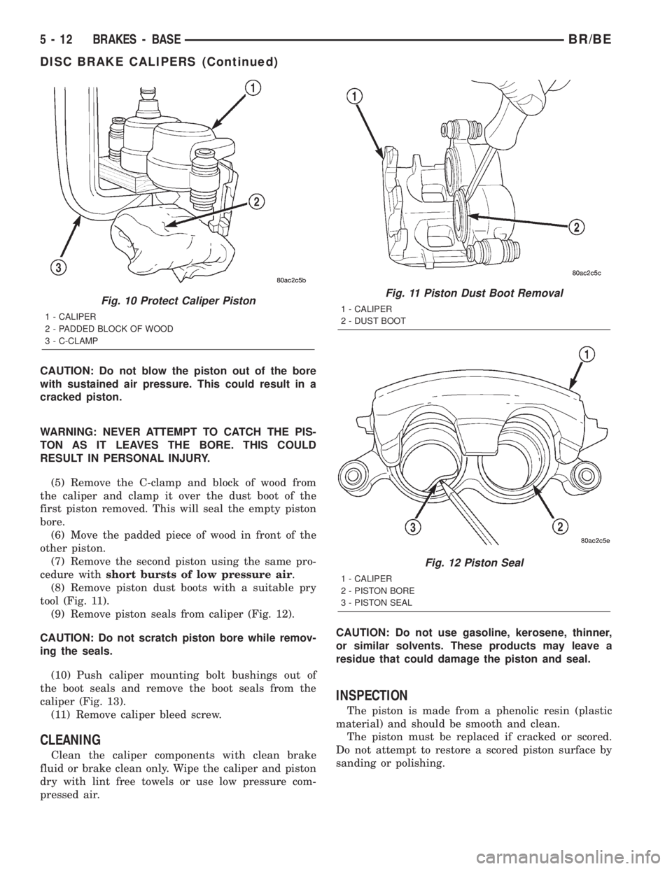
CAUTION: Do not blow the piston out of the bore
with sustained air pressure. This could result in a
cracked piston.
WARNING: NEVER ATTEMPT TO CATCH THE PIS-
TON AS IT LEAVES THE BORE. THIS COULD
RESULT IN PERSONAL INJURY.
(5) Remove the C-clamp and block of wood from
the caliper and clamp it over the dust boot of the
first piston removed. This will seal the empty piston
bore.
(6) Move the padded piece of wood in front of the
other piston.
(7) Remove the second piston using the same pro-
cedure withshort bursts of low pressure air.
(8) Remove piston dust boots with a suitable pry
tool (Fig. 11).
(9) Remove piston seals from caliper (Fig. 12).
CAUTION: Do not scratch piston bore while remov-
ing the seals.
(10) Push caliper mounting bolt bushings out of
the boot seals and remove the boot seals from the
caliper (Fig. 13).
(11) Remove caliper bleed screw.
CLEANING
Clean the caliper components with clean brake
fluid or brake clean only. Wipe the caliper and piston
dry with lint free towels or use low pressure com-
pressed air.CAUTION: Do not use gasoline, kerosene, thinner,
or similar solvents. These products may leave a
residue that could damage the piston and seal.
INSPECTION
The piston is made from a phenolic resin (plastic
material) and should be smooth and clean.
The piston must be replaced if cracked or scored.
Do not attempt to restore a scored piston surface by
sanding or polishing.
Fig. 10 Protect Caliper Piston
1 - CALIPER
2 - PADDED BLOCK OF WOOD
3 - C-CLAMP
Fig. 11 Piston Dust Boot Removal
1 - CALIPER
2 - DUST BOOT
Fig. 12 Piston Seal
1 - CALIPER
2 - PISTON BORE
3 - PISTON SEAL
5 - 12 BRAKES - BASEBR/BE
DISC BRAKE CALIPERS (Continued)
Page 206 of 2255

PEDAL
DESCRIPTION
The brake booster is operated by a suspended type
brake pedal. The pedal pivots on a shaft located in a
mounting bracket attached to the dash panel. The
pedal shaft is supported by bushings in the pedal
and mounting bracket. The brake pedal is attached
to the booster push rod.
OPERATION
When the pedal is depressed, the primary booster
push rod is depressed which move the booster sec-
ondary rod. The booster secondary rod depress the
master cylinder piston.
REMOVAL
(1) Remove knee bolster, (Refer to 23 - BODY/IN-
STRUMENT PANEL/STEERING COLUMN OPEN-
ING COVER - REMOVAL).
(2) Remove brake lamp switch, (Refer to 8 - ELEC-
TRICAL/LAMPS/LIGHTING - EXTERIOR/BRAKE
LAMP SWITCH - REMOVAL).
(3) Remove switches from tabs on brake lamp
switch bracket.
(4) Remove brake lamp switch bracket bolts and
remove bracket (Fig. 25).
(5) Remove clip and washer attaching booster push
rod and slide push rod off pedal.
(6) Remove E-clip from passenger side of pedal
shaft (Fig. 26). Use flat blade screwdriver to pry clip
out of shaft groove.
(7) Push shaft toward driver side of bracket just
enough to expose opposite E-clip. Then remove E-clip
with flat blade screwdriver.(8) Push pedal shaft back and out of passenger
side of bracket (Fig. 26).
(9) Remove pedal shaft, brake pedal, wave washer
and bushings from vehicle.
INSTALLATION
(1) Replace bracket and pedal bushings if neces-
sary. Lubricate shaft bores in bracket and pedal
before installing bushings with Mopar Multi-mileage
silicone grease.
(2) Apply liberal quantity of Mopar multi-mileage
grease to pedal shaft and to pedal and bracket bush-
ings.
(3) Position brake pedal in mounting bracket.
(4) Slide pedal shaft into bracket and through
pedal from passenger side.
(5) Push pedal shaft out driver side of mounting
bracket just enough to allow installation of retaining
E-clip.
(6) Install the wave washer between the bracket
and the pedal bushing on the passenger side.
(7) Push pedal shaft back toward passenger side of
bracket and install remaining E-clip on pedal shaft.
(8) Install booster push rod on brake pedal. Secure
push rod to pedal with washer and retaining clip.
(9) Install brake lamp switch bracket and switch,
(Refer to 8 - ELECTRICAL/LAMPS/LIGHTING -
Fig. 25 Brake Lamp Switch Bracket
1 - PEDAL BRACKET
2 - BRAKELIGHT SWITCH BRACKET
3 - BRACKET SCREWS (2)
Fig. 26 Brake Pedal Mounting (With Automatic
Transmission)
1 - PEDAL SHAFT
2 - SHAFT RETAINING E-CLIPS (2)
3 - BRAKE PEDAL
4 - PEDAL BUSHING (2)
5 - PEDAL MOUNTING BRACKET
BR/BEBRAKES - BASE 5 - 17
Page 208 of 2255
HYDRAULIC BOOSTER DIAGNOSIS CHART
CONDITION POSSIBLE CAUSES CORRECTION
Slow Brake Pedal Return 1. Excessive seal friction in booster. 1. Replace booster.
2. Faulty spool valve action. 2. Replace booster.
3. Restriction in booster return hose. 3. Replace hose.
4. Damaged input rod. 4. Replace booster.
Excessive Brake Pedal
Effort.1. Internal or external seal leakage. 1. Replace booster.
2. Faulty steering pump. 2. Replace pump.
Brakes Self Apply 1. Dump valve faulty. 1. Replace booster.
2. Contamination in hydraulic
system.2. Flush hydraulic system and replace
booster.
3. Restriction in booster return hose. 3. Replace hose.
Booster Chatter, Pedal
Vibration1. Slipping pump belt. 1. Replace power steering belt.
2. Low pump fluid level. 2. Fill pump and check for leaks.
Grabbing Brakes 1. Low pump flow. 1. Test and repair/replace pump.
2. Faulty spool valve action. 2. Replace booster.
STANDARD PROCEDURE - BLEEDING
The hydraulic booster is generally self-bleeding,
this procedure will normally bleed the air from the
booster. Normal driving and operation of the unit will
remove any remaining trapped air.
(1) Fill power steering pump reservoir.
(2) Disconnect fuel shutdown relay and crank the
engine for several seconds, Refer to Fuel System for
relay location and WARNING.
(3) Check fluid level and add if necessary.
(4) Connect fuel shutdown relay and start the
engine.
(5) Turn the steering wheel slowly from lock to
lock twice.
(6) Stop the engine and discharge the accumulator
by depressing the brake pedal 5 times.
(7) Start the engine and turn the steering wheel
slowly from lock to lock twice.
(8) Turn off the engine and check fluid level and
add if necessary.
NOTE: If fluid foaming occurs, wait for foam to dis-
sipate and repeat steps 7 and 8.
REMOVAL
NOTE: If the booster is being replaced because the
power steering fluid is contaminated, flush the
power steering system before replacing the booster.(1) With engine off depress the brake pedal 5
times to discharge the accumulator.
(2) Remove brake lines from master cylinder.
(3) Remove mounting nuts from the master cylin-
der.
(4) Remove the bracket from the hydraulic booster
lines and master cylinder mounting studs.
(5) Remove the master cylinder.
(6) Remove the return hose and the two pressure
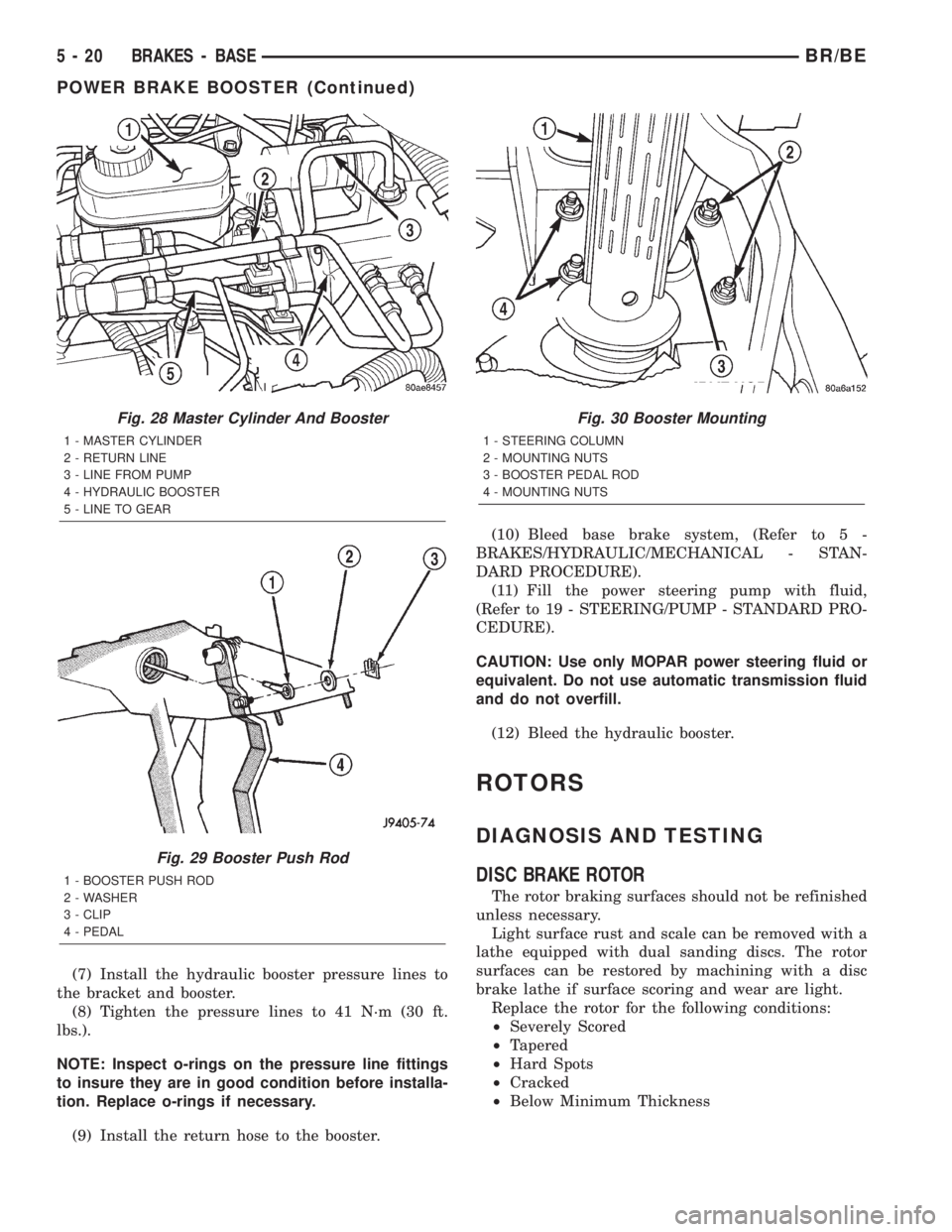
lines from the hydraulic booster (Fig. 28).
(7) Remove the booster push rod clip, washer and
rod remove from the brake pedal. (Fig. 29).
(8) Remove the mounting nuts from the hydraulic
booster and remove the booster (Fig. 30).
INSTALLATION
(1) Install the hydraulic booster and tighten the
mounting nuts to 28 N´m (21 ft. lbs.).
(2) Install the booster push rod, washer and clip
onto the brake pedal.
(3) Install the master cylinder on the mounting
studs. and tighten the mounting nuts to 23 N´m (17
ft. lbs.).
(4) Install the brake lines to the master cylinder
and tighten to 19-200 N´m (170-200 in. lbs.).
(5) Install the hydraulic booster line bracket onto
the master cylinder mounting studs.
(6) Install the master cylinder mounting nuts and
tighten to 23 N´m (17 ft. lbs.).
BR/BEBRAKES - BASE 5 - 19
POWER BRAKE BOOSTER (Continued)
Page 209 of 2255
(7) Install the hydraulic booster pressure lines to
the bracket and booster.
(8) Tighten the pressure lines to 41 N´m (30 ft.
lbs.).
NOTE: Inspect o-rings on the pressure line fittings
to insure they are in good condition before installa-
tion. Replace o-rings if necessary.
(9) Install the return hose to the booster.(10) Bleed base brake system, (Refer to 5 -
BRAKES/HYDRAULIC/MECHANICAL - STAN-
DARD PROCEDURE).
(11) Fill the power steering pump with fluid,
(Refer to 19 - STEERING/PUMP - STANDARD PRO-
CEDURE).
CAUTION: Use only MOPAR power steering fluid or
equivalent. Do not use automatic transmission fluid
and do not overfill.
(12) Bleed the hydraulic booster.
ROTORS
DIAGNOSIS AND TESTING
DISC BRAKE ROTOR
The rotor braking surfaces should not be refinished
unless necessary.
Light surface rust and scale can be removed with a
lathe equipped with dual sanding discs. The rotor
surfaces can be restored by machining with a disc
brake lathe if surface scoring and wear are light.
Replace the rotor for the following conditions:
²Severely Scored
²Tapered
²Hard Spots
²Cracked
²Below Minimum Thickness
Fig. 28 Master Cylinder And Booster
1 - MASTER CYLINDER
2 - RETURN LINE
3 - LINE FROM PUMP
4 - HYDRAULIC BOOSTER
5 - LINE TO GEAR
Fig. 29 Booster Push Rod
1 - BOOSTER PUSH ROD
2 - WASHER
3 - CLIP
4 - PEDAL
Fig. 30 Booster Mounting
1 - STEERING COLUMN
2 - MOUNTING NUTS
3 - BOOSTER PEDAL ROD
4 - MOUNTING NUTS
5 - 20 BRAKES - BASEBR/BE
POWER BRAKE BOOSTER (Continued)
Page 218 of 2255

(9) Remove the bolts/nuts from the pedal assembly
and remove the assembly.
INSTALLATION
(1) Position the replacement pedal assembly on the
dash and cowl.
(2) Install the bolts/nuts and tighten to 28 N´m (21
ft. lbs.).
(3) Connect the front cable to the arm on the pedal
assembly.
(4) Tighten the front cable grommet to the floor-
pan and the cable retainer, roll the carpet back.
(5) Connect the wires to the brake lamp switch.
(6) Install the knee bolster, (Refer to 23 - BODY/
INSTRUMENT PANEL/STEERING COLUMN
OPENING COVER - INSTALLATION).
(7) Raise the vehicle.
(8) Adjust the parking brake cable tensioner.
CABLES
REMOVAL
REMOVAL - REAR PARK BRAKE CABLE
(1) Raise and support the vehicle.
(2) Lockout the parking brake cable (Fig. 53).
(3) Loosen cable adjuster nut.
(4) Remove the rear park brake cable from the
intermediate park brake cable.(5) Compress tabs on cable end fitting on the rear
park brake cable to the frame mount bracket. Then
pull the cable through the bracket.
(6) Disengage the park brake cable from behind
the rotor assembly. (Fig. 54).
(7) Compress cable tabs on each cable end fitting
at the brake cable support plate.
(8) Remove the cables from the brake cable sup-
port plates.REMOVAL - FRONT PARKING BRAKE CABLE
(1) Raise and support vehicle.
(2) Loosen adjusting nut to create slack in front
cable.
Fig. 52 Parking Brake Pedal Assembly
1 - PARK BRAKE PEDAL
2 - FRONT CABLE
Fig. 53 LOCK OUT PARKING CABLE
1 - LOCKING PLIERS
2 - PARKING BRAKE CABLE
Fig. 54 DISENGAGEMENT OF CABLE
1 - LEVER
2 - CABLE END
BR/BEBRAKES - BASE 5 - 29
PEDAL (Continued)