2002 DODGE RAM RACK
[x] Cancel search: RACKPage 280 of 2255
NOISE DIAGNOSIS
Noises generated by the accessory drive belt are
most noticeable at idle. Before replacing a belt toresolve a noise condition, inspect all of the accessory
drive pulleys for alignment, glazing, or excessive end
play.
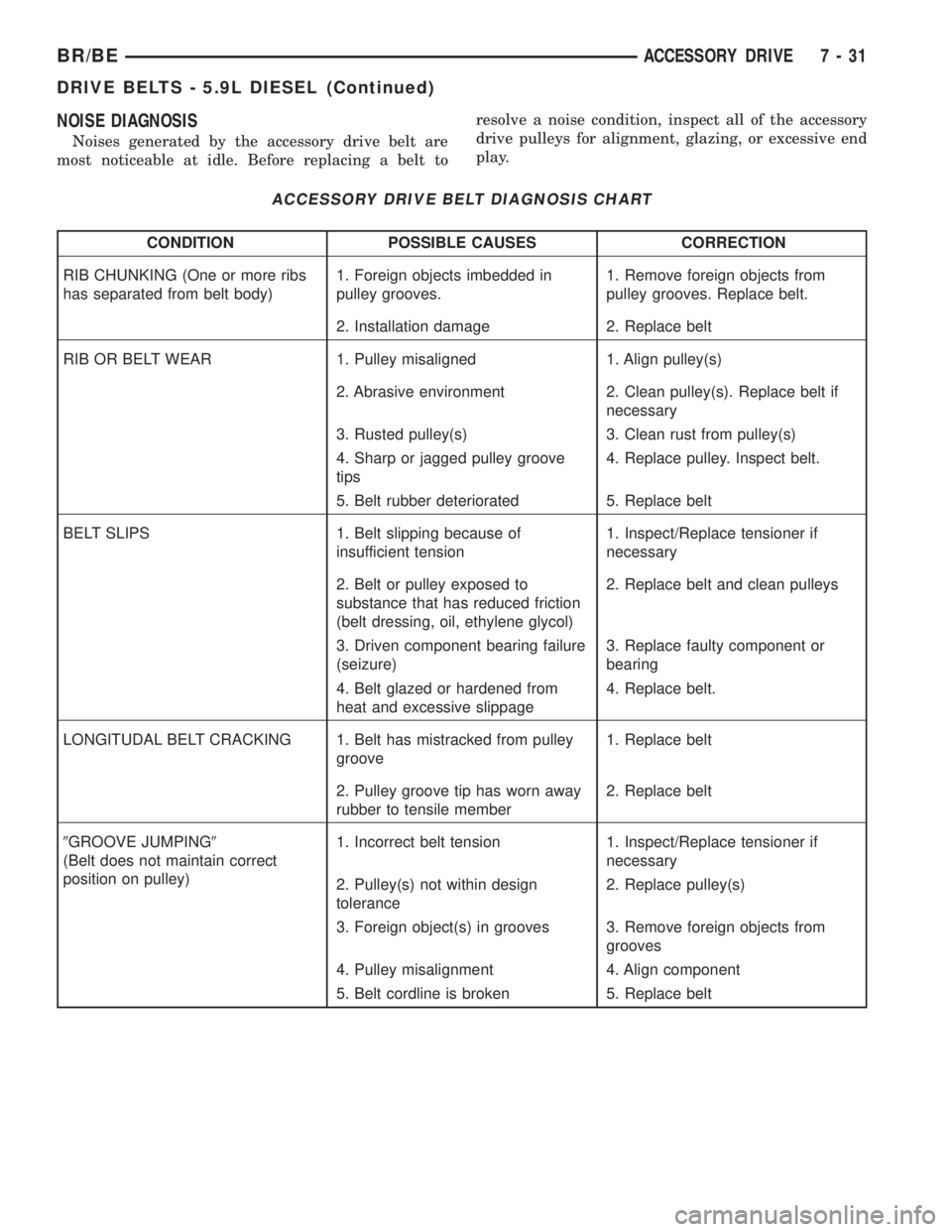
ACCESSORY DRIVE BELT DIAGNOSIS CHART
CONDITION POSSIBLE CAUSES CORRECTION
RIB CHUNKING (One or more ribs
has separated from belt body)1. Foreign objects imbedded in
pulley grooves.1. Remove foreign objects from
pulley grooves. Replace belt.
2. Installation damage 2. Replace belt
RIB OR BELT WEAR 1. Pulley misaligned 1. Align pulley(s)
2. Abrasive environment 2. Clean pulley(s). Replace belt if
necessary
3. Rusted pulley(s) 3. Clean rust from pulley(s)
4. Sharp or jagged pulley groove
tips4. Replace pulley. Inspect belt.
5. Belt rubber deteriorated 5. Replace belt
BELT SLIPS 1. Belt slipping because of
insufficient tension1. Inspect/Replace tensioner if
necessary
2. Belt or pulley exposed to
substance that has reduced friction
(belt dressing, oil, ethylene glycol)2. Replace belt and clean pulleys
3. Driven component bearing failure
(seizure)3. Replace faulty component or
bearing
4. Belt glazed or hardened from
heat and excessive slippage4. Replace belt.
LONGITUDAL BELT CRACKING 1. Belt has mistracked from pulley
groove1. Replace belt
2. Pulley groove tip has worn away
rubber to tensile member2. Replace belt
9GROOVE JUMPING9
(Belt does not maintain correct
position on pulley)1. Incorrect belt tension 1. Inspect/Replace tensioner if
necessary
2. Pulley(s) not within design
tolerance2. Replace pulley(s)
3. Foreign object(s) in grooves 3. Remove foreign objects from
grooves
4. Pulley misalignment 4. Align component
5. Belt cordline is broken 5. Replace belt
BR/BEACCESSORY DRIVE 7 - 31
DRIVE BELTS - 5.9L DIESEL (Continued)
Page 281 of 2255
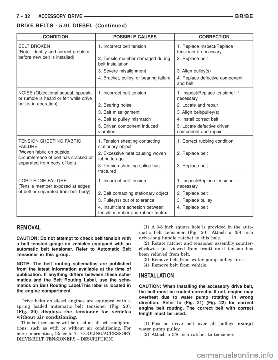
CONDITION POSSIBLE CAUSES CORRECTION
BELT BROKEN
(Note: Identify and correct problem
before new belt is installed)1. Incorrect belt tension 1. Replace Inspect/Replace
tensioner if necessary
2. Tensile member damaged during
belt installation2. Replace belt
3. Severe misalignment 3. Align pulley(s)
4. Bracket, pulley, or bearing failure 4. Replace defective component
and belt
NOISE (Objectional squeal, spueak,
or rumble is heard or felt while drive
belt is in operation)1. Incorrect belt tension 1. Inspect/Replace tensioner if
necessary
2. Bearing noise 2. Locate and repair
3. Belt misalignment 3. Align belt/pulley(s)
4. Belt to pulley mismatch 4. Install correct belt
5. Driven component induced
vibration5. Locate defective driven
component and repair
TENSION SHEETING FABRIC
FAILURE
(Woven fabric on outside,
circumference of belt has cracked or
separated from body of belt)1. Tension sheeting contacting
stationary object1. Correct rubbing condition
2. Excessive heat causing woven
fabric to age2. Replace belt
3. Tension sheeting splice has
fractured3. Replace belt
CORD EDGE FAILURE
(Tensile member exposed at edges
of belt or separated from belt body)1. Incorrect belt tension 1. Inspect/Replace tensioner if
necessary
2. Belt contacting stationary object 2. Replace belt
3. Pulley(s) out of tolerance 3. Replace pulley
4. Insufficient adhesion between
tensile member and rubber matrix4. Replace belt
REMOVAL
CAUTION: Do not attempt to check belt tension with
a belt tension gauge on vehicles equipped with an
automatic belt tensioner. Refer to Automatic Belt
Tensioner in this group.
NOTE: The belt routing schematics are published
from the latest information available at the time of
publication. If anything differs between these sche-
matics and the Belt Routing Label, use the sche-
matics on Belt Routing Label.This label is located in
the engine compartment.
Drive belts on diesel engines are equipped with a
spring loaded automatic belt tensioner (Fig. 20).
(Fig. 20) displays the tensioner for vehicles
without air conditioning.
This belt tensioner will be used on all belt configura-
tions, such as with or without air conditioning. For
more information, (Refer to 7 - COOLING/ACCESSORY
DRIVE/BELT TENSIONERS - DESCRIPTION).
(1) A 3/8 inch square hole is provided in the auto-
matic belt tensioner (Fig. 20). Attach a 3/8 inch
drive-long handle ratchet to this hole.
(2) Rotate ratchet and tensioner assembly counter-
clockwise (as viewed from front) until tension has
been relieved from belt.
(3) Remove belt from water pump pulley first.
(4) Remove belt from vehicle.
INSTALLATION
CAUTION: When installing the accessory drive belt,
the belt must be routed correctly. If not, engine may
overheat due to water pump rotating in wrong
direction. Refer to (Fig. 21) (Fig. 22) for correct
engine belt routing. The correct belt with correct
length must be used.
(1) Position drive belt over all pulleysexcept
water pump pulley.
(2) Attach a 3/8 inch ratchet to tensioner.
7 - 32 ACCESSORY DRIVEBR/BE
DRIVE BELTS - 5.9L DIESEL (Continued)
Page 283 of 2255
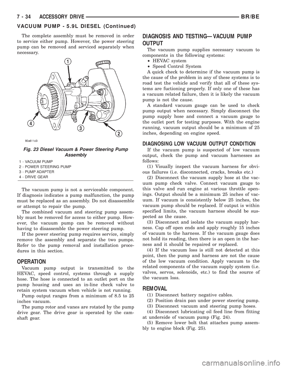
The complete assembly must be removed in order
to service either pump. However, the power steering
pump can be removed and serviced separately when
necessary.
The vacuum pump is not a serviceable component.
If diagnosis indicates a pump malfunction, the pump
must be replaced as an assembly. Do not disassemble
or attempt to repair the pump.
The combined vacuum and steering pump assem-
bly must be removed for access to either pump. How-
ever, the vacuum pump can be removed without
having to disassemble the power steering pump.
If the power steering pump requires service, simply
remove the assembly and separate the two pumps.
Refer to the pump removal and installation proce-
dures in this section.
OPERATION
Vacuum pump output is transmitted to the
HEVAC, speed control, systems through a supply
hose. The hose is connected to an outlet port on the
pump housing and uses an in-line check valve to
retain system vacuum when vehicle is not running.
Pump output ranges from a minimum of 8.5 to 25
inches vacuum.
The pump rotor and vanes are rotated by the pump
drive gear. The drive gear is operated by the cam-
shaft gear.
DIAGNOSIS AND TESTINGÐVACUUM PUMP
OUTPUT
The vacuum pump supplies necessary vacuum to
components in the following systems:
²HEVAC system
²Speed Control System
A quick check to determine if the vacuum pump is
the cause of the problem in any of these systems is to
road test the vehicle and verify that all of these sys-
tems are fuctioning properly. If only one of these has
a vacuum related failure, then it is likely the vacuum
pump is not the cause.
A standard vacuum gauge can be used to check
pump output when necessary. Simply disconnect the
pump supply hose and connect a vacuum gauge to
the outlet port for testing purposes. With the engine
running, vacuum output should be a minimum of 25
inches, depending on engine speed.
DIAGNOSING LOW VACUUM OUTPUT CONDITION
If the vacuum pump is suspected of low vacuum
output, check the pump and vacuum harnesses as
follows:
(1) Visually inspect the vacuum harness for obvi-
ous failures (i.e. disconnected, cracks, breaks etc.)
(2) Disconnect the vacuum supply hose at the vac-
uum pump check valve. Connect vacuum gauge to
this valve and run engine at various throttle open-
ings. Output should be a minimum 25 inches of vac-
uum. If vacuum is consistently below 25 inches, the
vacuum pump should be replaced. If output is within
specified limits, the vacuum harness should be sus-
pected as the cause.
(3) Disconnect and isolate the vacuum supply har-
ness. Cap off open ends and apply roughly 15 inches
of vacuum to the harness. If the vacuum gauge does
not hold its reading, then there is an open in the har-
ness and it should be repaired or replaced.
(4) If the vacuum loss is still not detected at this
point, then the pump and harness are not the cause
of the low vacuum condition. Apply vacuum to the
related components of the vacuum supply system (i.e.
valves, servos, solenoids, etc.) to find the source of
the vacuum loss.
REMOVAL
(1) Disconnect battery negative cables.
(2) Position drain pan under power steering pump.
(3) Disconnect vacuum and steering pump hoses.
(4) Disconnect lubricating oil feed line from fitting
at underside of vacuum pump (Fig. 24).
(5) Remove lower bolt that attaches pump assem-
bly to engine block (Fig. 25).
Fig. 23 Diesel Vacuum & Power Steering Pump
Assembly
1 - VACUUM PUMP
2 - POWER STEERING PUMP
3 - PUMP ADAPTER
4 - DRIVE GEAR
7 - 34 ACCESSORY DRIVEBR/BE
VACUUM PUMP - 5.9L DIESEL (Continued)
Page 284 of 2255
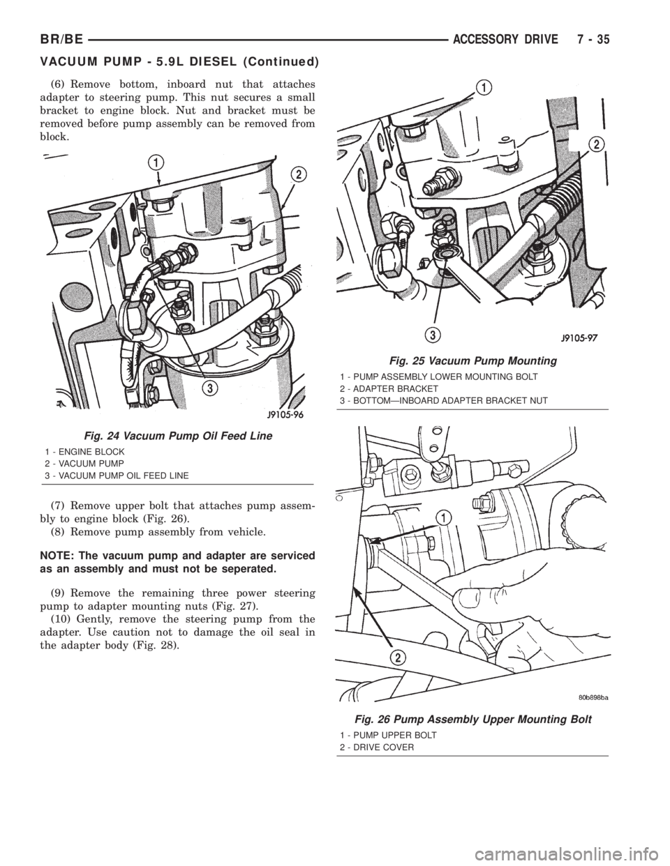
(6) Remove bottom, inboard nut that attaches
adapter to steering pump. This nut secures a small
bracket to engine block. Nut and bracket must be
removed before pump assembly can be removed from
block.
(7) Remove upper bolt that attaches pump assem-
bly to engine block (Fig. 26).
(8) Remove pump assembly from vehicle.
NOTE: The vacuum pump and adapter are serviced
as an assembly and must not be seperated.
(9) Remove the remaining three power steering
pump to adapter mounting nuts (Fig. 27).
(10) Gently, remove the steering pump from the
adapter. Use caution not to damage the oil seal in
the adapter body (Fig. 28).
Fig. 24 Vacuum Pump Oil Feed Line
1 - ENGINE BLOCK
2 - VACUUM PUMP
3 - VACUUM PUMP OIL FEED LINE
Fig. 25 Vacuum Pump Mounting
1 - PUMP ASSEMBLY LOWER MOUNTING BOLT
2 - ADAPTER BRACKET
3 - BOTTOMÐINBOARD ADAPTER BRACKET NUT
Fig. 26 Pump Assembly Upper Mounting Bolt
1 - PUMP UPPER BOLT
2 - DRIVE COVER
BR/BEACCESSORY DRIVE 7 - 35
VACUUM PUMP - 5.9L DIESEL (Continued)
Page 285 of 2255
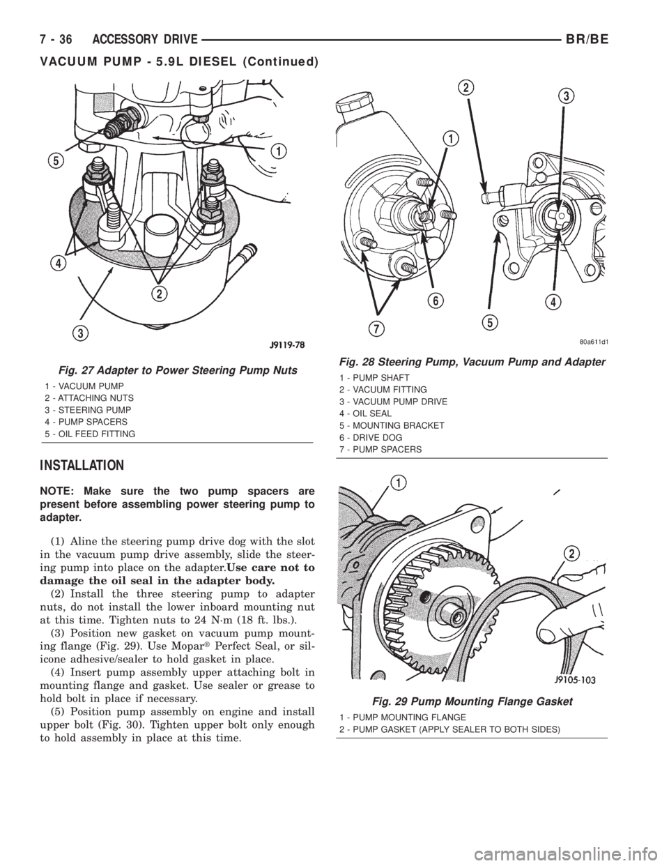
INSTALLATION
NOTE: Make sure the two pump spacers are
present before assembling power steering pump to
adapter.
(1) Aline the steering pump drive dog with the slot
in the vacuum pump drive assembly, slide the steer-
ing pump into place on the adapter.Use care not to
damage the oil seal in the adapter body.
(2) Install the three steering pump to adapter
nuts, do not install the lower inboard mounting nut
at this time. Tighten nuts to 24 N´m (18 ft. lbs.).
(3) Position new gasket on vacuum pump mount-
ing flange (Fig. 29). Use MopartPerfect Seal, or sil-
icone adhesive/sealer to hold gasket in place.
(4) Insert pump assembly upper attaching bolt in
mounting flange and gasket. Use sealer or grease to
hold bolt in place if necessary.
(5) Position pump assembly on engine and install
upper bolt (Fig. 30). Tighten upper bolt only enough
to hold assembly in place at this time.
Fig. 27 Adapter to Power Steering Pump Nuts
1 - VACUUM PUMP
2 - ATTACHING NUTS
3 - STEERING PUMP
4 - PUMP SPACERS
5 - OIL FEED FITTING
Fig. 28 Steering Pump, Vacuum Pump and Adapter
1 - PUMP SHAFT
2 - VACUUM FITTING
3 - VACUUM PUMP DRIVE
4 - OIL SEAL
5 - MOUNTING BRACKET
6 - DRIVE DOG
7 - PUMP SPACERS
Fig. 29 Pump Mounting Flange Gasket
1 - PUMP MOUNTING FLANGE
2 - PUMP GASKET (APPLY SEALER TO BOTH SIDES)
7 - 36 ACCESSORY DRIVEBR/BE
VACUUM PUMP - 5.9L DIESEL (Continued)
Page 286 of 2255

(6) Working from under vehicle, install pump
assembly lower attaching bolt. Then tighten upper
and lower bolt to 77 N´m (57 ft. lbs.).
(7) Position bracket on steering pump inboard
stud. Then install remaining adapter attaching nut
on stud. Tighten nut to 24 N´m (18 ft. lbs.).
(8) Connect oil feed line to vacuum pump connec-
tor and tighten line fitting.
(9) Connect steering pump pressure and return
lines to pump. Tighten pressure line fitting to 30
N´m (22 ft. lbs.).
(10) Connect vacuum hose to vacuum pump.
(11) Connect battery cables, if removed.
(12) Fill power steering pump reservoir and Purge
air from steering pump lines (Refer to 19 - STEER-
ING/PUMP - STANDARD PROCEDURE).
Fig. 30 Installing Pump Assembly On Engine
1 - PUMP ASSEMBLY
2 - PUMP GASKET
3 - DRIVE GEAR
BR/BEACCESSORY DRIVE 7 - 37
VACUUM PUMP - 5.9L DIESEL (Continued)
Page 290 of 2255

INSTALLATION
(1) Snap the tank into the two T-slots and the
alignment pin on fan shroud (Fig. 3).
(2) Connect overflow hose to radiator.
COOLANT RECOVERY
CONTAINER - 8.0L
DESCRIPTION
On the 8.0L V-10 engine the tank is mounted to
right inner fender (Fig. 4) , and is made of high tem-
perature plastic.
OPERATION
The coolant reserve/overflow system works in con-
junction with the radiator pressure cap. It utilizes
thermal expansion and contraction of coolant to keep
coolant free of trapped air. It provides a volume for
expansion and contraction of coolant. It also provides
a convenient and safe method for checking coolant
level and adjusting level at atmospheric pressure.
This is done without removing the radiator pressure
cap. The system also provides some reserve coolant
to the radiator to cover minor leaks and evaporation
or boiling losses.
As the engine cools, a vacuum is formed in the
cooling system of both the radiator and engine. Cool-ant will then be drawn from the coolant tank and
returned to a proper level in the radiator.
RADIATOR FAN - 5.9L/8.0L
REMOVAL
CAUTION: If the viscous fan drive is replaced
because of mechanical damage, the cooling fan
blades should also be inspected. Inspect for fatigue
cracks, loose blades, or loose rivets that could
have resulted from excessive vibration. Replace fan
blade assembly if any of these conditions are
found. Also inspect water pump bearing and shaft
assembly for any related damage due to a viscous
fan drive malfunction.
(1) Disconnect negative battery cable from battery.
(2) Remove throttle cable at top of fan shroud.
(3) All Except 8.0L V-10 Engine: Unsnap coolant
reserve/overflow tank from fan shroud and lay aside.
The tank is held to shroud with T- shaped slots. Do
not disconnect hose or drain coolant from tank.
(4) The thermal viscous fan drive/fan blade assem-
bly is attached (threaded) to water pump hub shaft
(Fig. 6). Remove fan blade/viscous fan drive assembly
from water pump by turning mounting nut counter-
clockwise as viewed from front. Threads on viscous
fan drive areRIGHT-HAND.A Snap-On 36 MM Fan
Wrench (number SP346 from Snap-On Cummins Die-
sel Tool Set number 2017DSP), Special Tool 6958
Spanner Wrench and Adapter Pins 8346 should be
used to prevent pulley from rotating (Fig. 5).
Fig. 3 COOLANT RESERVE/OVERFLOW TANKÐALL
EXCEPT 8.0L V-10 ENGINE
1 - T-SLOTS
2 - ALIGNMENT PIN
3 - FAN SHROUD
4 - COOLANT RESERVE/OVERFLOW TANK
Fig. 4 Coolant Reserve/Overflow TankÐ8.0L V-10
Engine
1 - COOLANT RESERVE/OVERFLOW TANK
2 - TANK MOUNTING BOLTS (3)
3 - ICM MOUNTING BOLTS (2)
4 - IGNITION CONTROL MODULE (ICM)
BR/BEENGINE 7 - 41
COOLANT RECOVERY CONTAINER - 3.9L/5.2L/5.9L/5.9L DIESEL (Continued)
Page 291 of 2255
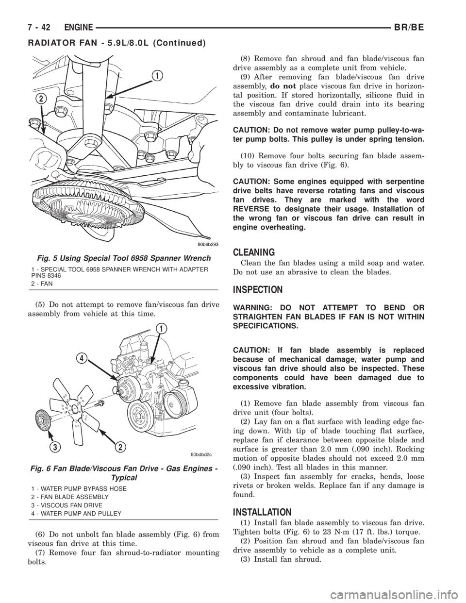
(5) Do not attempt to remove fan/viscous fan drive
assembly from vehicle at this time.
(6) Do not unbolt fan blade assembly (Fig. 6) from
viscous fan drive at this time.
(7) Remove four fan shroud-to-radiator mounting
bolts.(8) Remove fan shroud and fan blade/viscous fan
drive assembly as a complete unit from vehicle.
(9) After removing fan blade/viscous fan drive
assembly,do notplace viscous fan drive in horizon-
tal position. If stored horizontally, silicone fluid in
the viscous fan drive could drain into its bearing
assembly and contaminate lubricant.
CAUTION: Do not remove water pump pulley-to-wa-
ter pump bolts. This pulley is under spring tension.
(10) Remove four bolts securing fan blade assem-
bly to viscous fan drive (Fig. 6).
CAUTION: Some engines equipped with serpentine
drive belts have reverse rotating fans and viscous
fan drives. They are marked with the word
REVERSE to designate their usage. Installation of
the wrong fan or viscous fan drive can result in
engine overheating.
CLEANING
Clean the fan blades using a mild soap and water.
Do not use an abrasive to clean the blades.
INSPECTION
WARNING: DO NOT ATTEMPT TO BEND OR
STRAIGHTEN FAN BLADES IF FAN IS NOT WITHIN
SPECIFICATIONS.
CAUTION: If fan blade assembly is replaced
because of mechanical damage, water pump and
viscous fan drive should also be inspected. These
components could have been damaged due to
excessive vibration.
(1) Remove fan blade assembly from viscous fan
drive unit (four bolts).
(2) Lay fan on a flat surface with leading edge fac-
ing down. With tip of blade touching flat surface,
replace fan if clearance between opposite blade and
surface is greater than 2.0 mm (.090 inch). Rocking
motion of opposite blades should not exceed 2.0 mm
(.090 inch). Test all blades in this manner.
(3) Inspect fan assembly for cracks, bends, loose
rivets or broken welds. Replace fan if any damage is
found.
INSTALLATION
(1) Install fan blade assembly to viscous fan drive.
Tighten bolts (Fig. 6) to 23 N´m (17 ft. lbs.) torque.
(2) Position fan shroud and fan blade/viscous fan
drive assembly to vehicle as a complete unit.
(3) Install fan shroud.
Fig. 5 Using Special Tool 6958 Spanner Wrench
1 - SPECIAL TOOL 6958 SPANNER WRENCH WITH ADAPTER
PINS 8346
2-FAN
Fig. 6 Fan Blade/Viscous Fan Drive - Gas Engines -
Typical
1 - WATER PUMP BYPASS HOSE
2 - FAN BLADE ASSEMBLY
3 - VISCOUS FAN DRIVE
4 - WATER PUMP AND PULLEY
7 - 42 ENGINEBR/BE
RADIATOR FAN - 5.9L/8.0L (Continued)