2002 DODGE RAM integrated power module
[x] Cancel search: integrated power modulePage 366 of 2255

ELECTRONIC CONTROL MODULES
TABLE OF CONTENTS
page page
CENTRAL TIMER MODULE
DESCRIPTION..........................1
OPERATION............................3
DIAGNOSIS AND TESTING - CENTRAL TIMER
MODULE.............................4
REMOVAL.............................5
INSTALLATION..........................6
COMMUNICATION
DESCRIPTION - CCD DATA BUS............6
OPERATION - CCD DATA BUS..............7
DIAGNOSIS AND TESTING - CCD DATA BUS . . 11
CONTROLLER ANTILOCK BRAKE
DESCRIPTION.........................11
OPERATION...........................11
REMOVAL.............................11
INSTALLATION.........................12
DATA LINK CONNECTOR
DESCRIPTION - DATA LINK CONNECTOR....12
OPERATION - DATA LINK CONNECTOR......12
ENGINE CONTROL MODULE
DESCRIPTION - ECM....................13
OPERATION - ECM.....................13
REMOVAL.............................14
INSTALLATION.........................14POWERTRAIN CONTROL MODULE
DESCRIPTION
DESCRIPTION - PCM..................15
DESCRIPTION - MODES OF OPERATION . . . 15
DESCRIPTION - 5 VOLT SUPPLIES.......17
DESCRIPTION - IGNITION CIRCUIT SENSE . 17
DESCRIPTION - POWER GROUNDS......17
DESCRIPTION - SENSOR RETURN.......17
DESCRIPTION - SIGNAL GROUND........17
OPERATION
OPERATION - PCM - GAS ENGINES.......18
OPERATION - DIESEL..................18
OPERATION - 5 VOLT SUPPLIES.........19
OPERATION - IGNITION CIRCUIT SENSE . . . 19
REMOVAL.............................19
INSTALLATION.........................20
HEATED SEAT MODULE
DESCRIPTION.........................20
OPERATION...........................20
DIAGNOSIS AND TESTING - HEATED SEAT
MODULE............................21
REMOVAL.............................23
INSTALLATION.........................23
CENTRAL TIMER MODULE
DESCRIPTION
Three versions of the Central Timer Module (CTM)
are available on this vehicle, a base version (Fig. 1),
a high-line version (Fig. 2), and a premium version.
Whichever version of the CTM the vehicle is
equipped with, it is concealed under the driver side
end of the instrument panel inboard of the instru-
ment panel steering column opening, where it is
secured to a stamped steel bracket that is integral to
the instrument panel armature. The CTM is enclosed
in a molded plastic housing with one (base) or two
(high-line/premium) integral external connector
receptacles that connect it to the vehicle electrical
system through one (base) or two (high-line/pre-
mium) take outs with connectors from the instru-
ment panel wire harness.
The base version of the CTM is used on base mod-
els of this vehicle. It is also sometimes referred to as
the Integrated Electronic Module (IEM). The base
version of the CTM combines the functions of achime module and an intermittent wipe module in a
single unit. The high-line version of the CTM is used
on high-line vehicles. The high-line CTM provides all
of the functions of the base version of the CTM, but
also is used to control and integrate many additional
electronic functions and features included on high-
line models. The premium version of the CTM is the
same as the high-line version, but is used only on
models equipped with the heated seat option.
The high-line and premium versions of the CTM
utilize integrated circuitry and information carried
on the Chrysler Collision Detection (CCD) data bus
network along with many hard wired inputs to mon-
itor many sensor and switch inputs throughout the
vehicle. In response to those inputs, the internal cir-
cuitry and programming of the CTM allow it to con-
trol and integrate many electronic functions and
features of the vehicle through both hard wired out-
puts and the transmission of electronic message out-
puts to other electronic modules in the vehicle over
the CCD data bus.
BR/BEELECTRONIC CONTROL MODULES 8E - 1
Page 624 of 2255
SPEED CONTROL
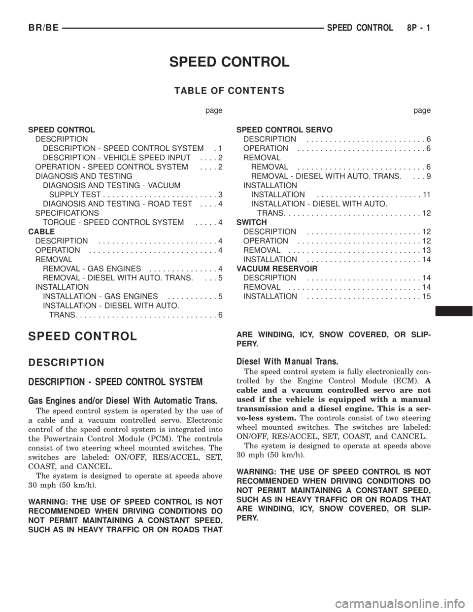
TABLE OF CONTENTS
page page
SPEED CONTROL
DESCRIPTION
DESCRIPTION - SPEED CONTROL SYSTEM . 1
DESCRIPTION - VEHICLE SPEED INPUT....2
OPERATION - SPEED CONTROL SYSTEM....2
DIAGNOSIS AND TESTING
DIAGNOSIS AND TESTING - VACUUM
SUPPLY TEST.........................3
DIAGNOSIS AND TESTING - ROAD TEST....4
SPECIFICATIONS
TORQUE - SPEED CONTROL SYSTEM.....4
CABLE
DESCRIPTION..........................4
OPERATION............................4
REMOVAL
REMOVAL - GAS ENGINES...............4
REMOVAL - DIESEL WITH AUTO. TRANS. . . . 5
INSTALLATION
INSTALLATION - GAS ENGINES...........5
INSTALLATION - DIESEL WITH AUTO.
TRANS...............................6SPEED CONTROL SERVO
DESCRIPTION..........................6
OPERATION............................6
REMOVAL
REMOVAL............................6
REMOVAL - DIESEL WITH AUTO. TRANS. . . . 9
INSTALLATION
INSTALLATION.......................11
INSTALLATION - DIESEL WITH AUTO.
TRANS..............................12
SWITCH
DESCRIPTION.........................12
OPERATION...........................12
REMOVAL.............................13
INSTALLATION.........................14
VACUUM RESERVOIR
DESCRIPTION.........................14
REMOVAL.............................14
INSTALLATION.........................15
SPEED CONTROL
DESCRIPTION
DESCRIPTION - SPEED CONTROL SYSTEM
Gas Engines and/or Diesel With Automatic Trans.
The speed control system is operated by the use of
a cable and a vacuum controlled servo. Electronic
control of the speed control system is integrated into
the Powertrain Control Module (PCM). The controls
consist of two steering wheel mounted switches. The
switches are labeled: ON/OFF, RES/ACCEL, SET,
COAST, and CANCEL.
The system is designed to operate at speeds above
30 mph (50 km/h).
WARNING: THE USE OF SPEED CONTROL IS NOT
RECOMMENDED WHEN DRIVING CONDITIONS DO
NOT PERMIT MAINTAINING A CONSTANT SPEED,
SUCH AS IN HEAVY TRAFFIC OR ON ROADS THATARE WINDING, ICY, SNOW COVERED, OR SLIP-
PERY.
Diesel With Manual Trans.
The speed control system is fully electronically con-
trolled by the Engine Control Module (ECM).A
cable and a vacuum controlled servo are not
used if the vehicle is equipped with a manual
transmission and a diesel engine. This is a ser-
vo-less system.The controls consist of two steering
wheel mounted switches. The switches are labeled:
ON/OFF, RES/ACCEL, SET, COAST, and CANCEL.
The system is designed to operate at speeds above
30 mph (50 km/h).
WARNING: THE USE OF SPEED CONTROL IS NOT
RECOMMENDED WHEN DRIVING CONDITIONS DO
NOT PERMIT MAINTAINING A CONSTANT SPEED,
SUCH AS IN HEAVY TRAFFIC OR ON ROADS THAT
ARE WINDING, ICY, SNOW COVERED, OR SLIP-
PERY.
BR/BESPEED CONTROL 8P - 1