2002 DODGE RAM RACK
[x] Cancel search: RACKPage 244 of 2255
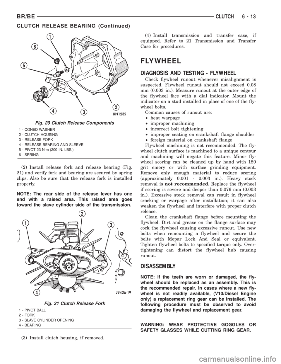
(2) Install release fork and release bearing (Fig.
21) and verify fork and bearing are secured by spring
clips. Also be sure that the release fork is installed
properly.
NOTE: The rear side of the release lever has one
end with a raised area. This raised area goes
toward the slave cylinder side of the transmission.
(3) Install clutch housing, if removed.(4) Install transmission and transfer case, if
equipped. Refer to 21 Transmission and Transfer
Case for procedures.
FLYWHEEL
DIAGNOSIS AND TESTING - FLYWHEEL
Check flywheel runout whenever misalignment is
suspected. Flywheel runout should not exceed 0.08
mm (0.003 in.). Measure runout at the outer edge of
the flywheel face with a dial indicator. Mount the
indicator on a stud installed in place of one of the fly-
wheel bolts.
Common causes of runout are:
²heat warpage
²improper machining
²incorrect bolt tightening
²improper seating on crankshaft flange shoulder
²foreign material on crankshaft flange
Flywheel machining is not recommended. The fly-
wheel clutch surface is machined to a unique contour
and machining will negate this feature. Minor fly-
wheel scoring can be cleaned up by hand with 180
grit emery or with surface grinding equipment.
Remove only enough material to reduce scoring
(approximately 0.001 - 0.003 in.). Heavy stock
removal isnot recommended.Replace the flywheel
if scoring is severe and deeper than 0.076 mm (0.003
in.). Excessive stock removal can result in flywheel
cracking or warpage after installation; it can also
weaken the flywheel and interfere with proper clutch
release.
Clean the crankshaft flange before mounting the
flywheel. Dirt and grease on the flange surface may
cock the flywheel causing excessive runout. Use new
bolts when remounting a flywheel and secure the
bolts with Mopar Lock And Seal or equivalent.
Tighten flywheel bolts to specified torque only. Over-
tightening can distort the flywheel hub causing
runout.
DISASSEMBLY
NOTE: If the teeth are worn or damaged, the fly-
wheel should be replaced as an assembly. This is
the recommended repair. In cases where a new fly-
wheel is not readily available, (V10/Diesel Engine
only) a replacement ring gear can be installed. The
following procedure must be observed to avoid
damaging the flywheel and replacement gear.
WARNING: WEAR PROTECTIVE GOGGLES OR
SAFETY GLASSES WHILE CUTTING RING GEAR.
Fig. 20 Clutch Release Components
1 - CONED WASHER
2 - CLUTCH HOUSING
3 - RELEASE FORK
4 - RELEASE BEARING AND SLEEVE
5 - PIVOT 23 N´m (200 IN. LBS.)
6 - SPRING
Fig. 21 Clutch Release Fork
1 - PIVOT BALL
2 - FORK
3 - SLAVE CYLINDER OPENING
4 - BEARING
BR/BECLUTCH 6 - 13
CLUTCH RELEASE BEARING (Continued)
Page 245 of 2255
(1) Mark position of the old gear for alignment ref-
erence on the flywheel. Use a scriber for this pur-
pose.
(2) Remove the old gear by cutting most of the way
through it (at one point) with an abrasive cut-off
wheel. Then complete removal with a cold chisel or
punch.
ASSEMBLY
NOTE: The ring gear is a shrink fit on the flywheel.
This means the gear must be expanded by heating
in order to install it. The method of heating and
expanding the gear is extremely important. Every
surface of the gear must be heated at the same
time to produce uniform expansion. An oven or
similar enclosed heating device must be used. Tem-
perature required for uniform expansion is approxi-
mately 375É F.
CAUTION: Do not use an oxy/acetylene torch to
remove the old gear, or to heat and expand a new
gear. The high temperature of the torch flame can
cause localized heating that will damage the fly-
wheel. In addition, using the torch to heat a replace-
ment gear will cause uneven heating and
expansion. The torch flame can also anneal the
gear teeth resulting in rapid wear and damage after
installation.
WARNING: WEAR PROTECTIVE GOGGLES OR
SAFETY GLASSES AND HEAT RESISTENT GLOVES
WHEN HANDLING A HEATED RING GEAR.
(1) The heated gear must be installed evenly to
avoid misalignment or distortion.
(2) Position and install the heated ring gear on the
flywheel with a shop press and a suitable press
plates.
(3) Place flywheel on work bench and let it cool in
normal shop air. Allow the ring gear to cool down
completely before installation it on the engine.
CAUTION: Do not use water or compressed air to
cool the flywheel. The rapid cooling produced by
water or compressed air will distort or crack the
new gear.
PILOT BEARING
REMOVAL
(1) Remove transmission, transfer case, if
equipped and clutch housing. Refer to 21 Transmis-
sion and Transfer Case for procedures.
(2) Remove pressure plate and disc.
(3) Using a suitable blind hole puller to remove
pilot bearing.
INSTALLATION
(1) Clean bearing bore with solvent and wipe dry
with shop towel.
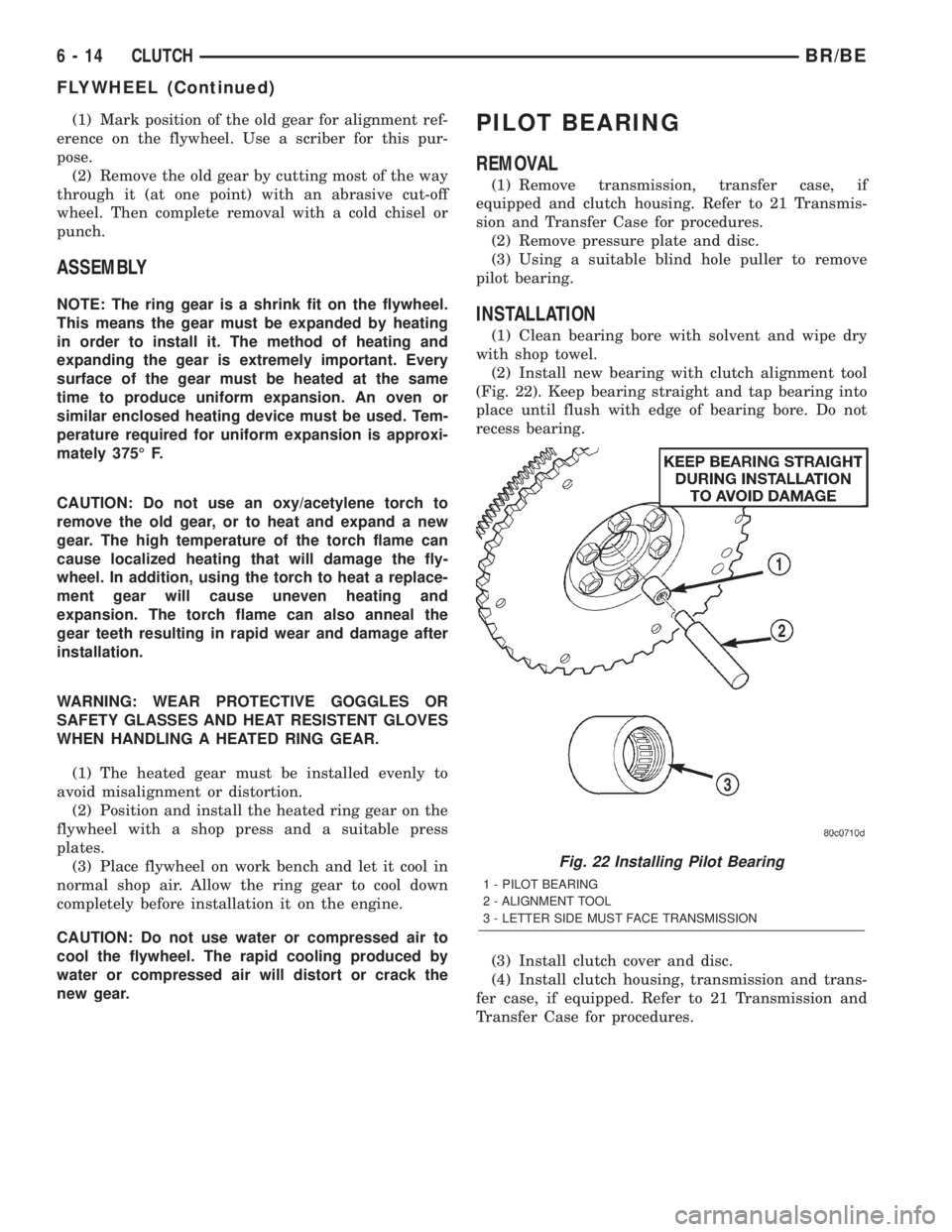
(2) Install new bearing with clutch alignment tool
(Fig. 22). Keep bearing straight and tap bearing into
place until flush with edge of bearing bore. Do not
recess bearing.
(3) Install clutch cover and disc.
(4) Install clutch housing, transmission and trans-
fer case, if equipped. Refer to 21 Transmission and
Transfer Case for procedures.
Fig. 22 Installing Pilot Bearing
1 - PILOT BEARING
2 - ALIGNMENT TOOL
3 - LETTER SIDE MUST FACE TRANSMISSION
6 - 14 CLUTCHBR/BE
FLYWHEEL (Continued)
Page 246 of 2255
CLUTCH PEDAL
REMOVAL
(1) Remove knee bolster for access to pedal pivot
shaft.
(2) Remove brake lamp switch.
(3) Remove retaining clips that secure the brake
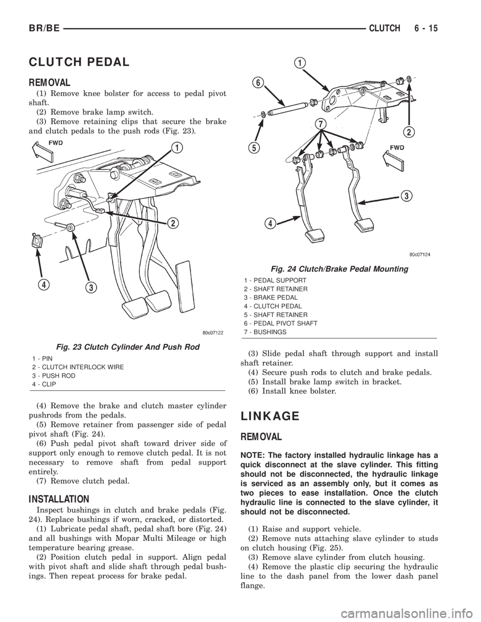
and clutch pedals to the push rods (Fig. 23).
(4) Remove the brake and clutch master cylinder
pushrods from the pedals.
(5) Remove retainer from passenger side of pedal
pivot shaft (Fig. 24).
(6) Push pedal pivot shaft toward driver side of
support only enough to remove clutch pedal. It is not
necessary to remove shaft from pedal support
entirely.
(7) Remove clutch pedal.
INSTALLATION
Inspect bushings in clutch and brake pedals (Fig.
24). Replace bushings if worn, cracked, or distorted.
(1) Lubricate pedal shaft, pedal shaft bore (Fig. 24)
and all bushings with Mopar Multi Mileage or high
temperature bearing grease.
(2) Position clutch pedal in support. Align pedal
with pivot shaft and slide shaft through pedal bush-
ings. Then repeat process for brake pedal.(3) Slide pedal shaft through support and install
shaft retainer.
(4) Secure push rods to clutch and brake pedals.
(5) Install brake lamp switch in bracket.
(6) Install knee bolster.
LINKAGE
REMOVAL
NOTE: The factory installed hydraulic linkage has a
quick disconnect at the slave cylinder. This fitting
should not be disconnected, the hydraulic linkage
is serviced as an assembly only, but it comes as
two pieces to ease installation. Once the clutch
hydraulic line is connected to the slave cylinder, it
should not be disconnected.
(1) Raise and support vehicle.
(2) Remove nuts attaching slave cylinder to studs
on clutch housing (Fig. 25).
(3) Remove slave cylinder from clutch housing.
(4) Remove the plastic clip securing the hydraulic
line to the dash panel from the lower dash panel
flange.
Fig. 23 Clutch Cylinder And Push Rod
1 - PIN
2 - CLUTCH INTERLOCK WIRE
3 - PUSH ROD
4 - CLIP
Fig. 24 Clutch/Brake Pedal Mounting
1 - PEDAL SUPPORT
2 - SHAFT RETAINER
3 - BRAKE PEDAL
4 - CLUTCH PEDAL
5 - SHAFT RETAINER
6 - PEDAL PIVOT SHAFT
7 - BUSHINGS
BR/BECLUTCH 6 - 15
Page 254 of 2255
DIAGNOSIS AND TESTINGÐON-BOARD
DIAGNOSTICS (OBD)
COOLING SYSTEM RELATED DIAGNOSTICS
The powertrain control module (PCM) has been
programmed to monitor certain cooling system com-
ponents:
²If the engine has remained cool for too long a
period, such as with a stuck open thermostat, a Diag-
nostic Trouble Code (DTC) can be set.
²If an open or shorted condition has developed in
the relay circuit controlling the electric radiator fan,
a Diagnostic Trouble Code (DTC) can be set.
If the problem is sensed in a monitored circuit
often enough to indicated an actual problem, a DTC
is stored. The DTC will be stored in the PCM mem-
ory for eventual display to the service technician.
(Refer to 25 - EMISSIONS CONTROL - DESCRIP-
TION).
ACCESSING DIAGNOSTIC TROUBLE CODES
To read DTC's and to obtain cooling system data,
(Refer to 25 - EMISSIONS CONTROL - DESCRIP-
TION).
ERASING TROUBLE CODES
After the problem has been repaired, use the DRB
scan tool to erase a DTC. Refer to the appropriate
Powertrain Diagnostic Procedures service informa-
tion for operation of the DRB scan tool.
DIAGNOSIS AND TESTING - COOLING SYSTEM
LEAKS
ULTRAVIOLET LIGHT METHOD
A leak detection additive is available through the
parts department that can be added to cooling sys-
tem. The additive is highly visible under ultraviolet
light (black light). Pour one ounce of additive into
cooling system. Place heater control unit in HEAT
position. Start and operate engine until radiator
upper hose is warm to touch. Aim the commercially
available black light tool at components to be
checked. If leaks are present, black light will cause
additive to glow a bright green color.
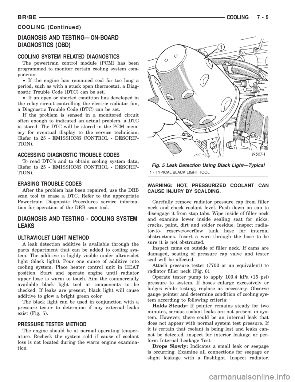
The black light can be used in conjunction with a
pressure tester to determine if any external leaks
exist (Fig. 5).
PRESSURE TESTER METHOD
The engine should be at normal operating temper-
ature. Recheck the system cold if cause of coolant
loss is not located during the warm engine examina-
tion.WARNING: HOT, PRESSURIZED COOLANT CAN
CAUSE INJURY BY SCALDING.
Carefully remove radiator pressure cap from filler
neck and check coolant level. Push down on cap to
disengage it from stop tabs. Wipe inside of filler neck
and examine lower inside sealing seat for nicks,
cracks, paint, dirt and solder residue. Inspect radia-
tor-to- reserve/overflow tank hose for internal
obstructions. Insert a wire through the hose to be
sure it is not obstructed.
Inspect cams on outside of filler neck. If cams are
damaged, seating of pressure cap valve and tester
seal will be affected.
Attach pressure tester (7700 or an equivalent) to
radiator filler neck (Fig. 6).
Operate tester pump to apply 103.4 kPa (15 psi)
pressure to system. If hoses enlarge excessively or
bulges while testing, replace as necessary. Observe
gauge pointer and determine condition of cooling sys-
tem according to following criteria:
Holds Steady:If pointer remains steady for two
minutes, serious coolant leaks are not present in sys-
tem. However, there could be an internal leak that
does not appear with normal system test pressure. If
it is certain that coolant is being lost and leaks can-
not be detected, inspect for interior leakage or per-
form Internal Leakage Test.
Drops Slowly:Indicates a small leak or seepage
is occurring. Examine all connections for seepage or
slight leakage with a flashlight. Inspect radiator,
Fig. 5 Leak Detection Using Black LightÐTypical
1 - TYPICAL BLACK LIGHT TOOL
BR/BECOOLING 7 - 5
COOLING (Continued)
Page 255 of 2255

hoses, gasket edges and heater. Seal small leak holes
with a Sealer Lubricant (or equivalent). Repair leak
holes and inspect system again with pressure
applied.
Drops Quickly:Indicates that serious leakage is
occurring. Examine system for external leakage. If
leaks are not visible, inspect for internal leakage.
Large radiator leak holes should be repaired by a
reputable radiator repair shop.
INTERNAL LEAKAGE INSPECTION
Remove engine oil pan drain plug and drain a
small amount of engine oil. If coolant is present in
the pan, it will drain first because it is heavier than
oil. An alternative method is to operate engine for a
short period to churn the oil. After this is done,
remove engine dipstick and inspect for water glob-
ules. Also inspect transmission dipstick for water
globules and transmission fluid cooler for leakage.
WARNING: WITH RADIATOR PRESSURE TESTER
TOOL INSTALLED ON RADIATOR, DO NOT ALLOW
PRESSURE TO EXCEED 110 KPA (20 PSI). PRES-
SURE WILL BUILD UP QUICKLY IF A COMBUSTION
LEAK IS PRESENT. TO RELEASE PRESSURE,
ROCK TESTER FROM SIDE TO SIDE. WHEN
REMOVING TESTER, DO NOT TURN TESTER MORE
THAN 1/2 TURN IF SYSTEM IS UNDER PRESSURE.
Operate engine without pressure cap on radiator
until thermostat opens. Attach a Pressure Tester to
filler neck. If pressure builds up quickly it indicates acombustion leak exists. This is usually the result of a
cylinder head gasket leak or crack in engine. Repair
as necessary.
If there is not an immediate pressure increase,
pump the Pressure Tester. Do this until indicated
pressure is within system range of 110 kPa (16 psi).
Fluctuation of gauge pointer indicates compression or
combustion leakage into cooling system.
Because the vehicle is equipped with a catalytic
converter,do notremove spark plug cables or short
out cylinders to isolate compression leak.
If the needle on dial of pressure tester does not
fluctuate, race engine a few times to check for an
abnormal amount of coolant or steam. This would be
emitting from exhaust pipe. Coolant or steam from
exhaust pipe may indicate a faulty cylinder head gas-
ket, cracked engine cylinder block or cylinder head.
A convenient check for exhaust gas leakage into
cooling system is provided by a commercially avail-
able Block Leak Check tool. Follow manufacturers
instructions when using this product.
COMBUSTION LEAKAGE TEST - WITHOUT
PRESSURE TESTER
DO NOT WASTE reusable coolant. If solution is
clean, drain coolant into a clean container for reuse.
WARNING: DO NOT REMOVE CYLINDER BLOCK
DRAIN PLUGS OR LOOSEN RADIATOR DRAIN-
COCK WITH SYSTEM HOT AND UNDER PRESSURE.
SERIOUS BURNS FROM COOLANT CAN OCCUR.
Drain sufficient coolant to allow thermostat
removal. (Refer to 7 - COOLING/ENGINE/ENGINE
COOLANT THERMOSTAT - REMOVAL). Remove
accessory drive belt (Refer to 7 - COOLING/ACCES-
SORY DRIVE/DRIVE BELTS - REMOVAL).
Add coolant to radiator to bring level to within 6.3
mm (1/4 in) of top of thermostat housing.
CAUTION: Avoid overheating. Do not operate
engine for an excessive period of time. Open drain-
cock immediately after test to eliminate boil over.
Start engine and accelerate rapidly three times, to
approximately 3000 rpm while observing coolant. If
internal engine combustion gases are leaking into
cooling system, bubbles will appear in coolant. If bub-
bles do not appear, internal combustion gas leakage
is not present.
Fig. 6 Pressure Testing Cooling SystemÐTypical
1 - TYPICAL COOLING SYSTEM PRESSURE TESTER
7 - 6 COOLINGBR/BE
COOLING (Continued)
Page 267 of 2255

SPECIFICATIONS
TORQUE
DESCRIPTION N´m Ft. In.
Lbs. Lbs
Belt Tensioner Pulley 5.9L
Engine-Bolt 61 45 Ð
Belt Tensioner Pulley 8.0L
EngineÐ
Bolt 88 65 Ð
Belt Tensioner to Mounting
BracketÐ
Bolt 5.9L Engine 67 50 Ð
Belt Tensioner to Mounting
BracketÐ
Bolt 8.0L Engine 41 30 Ð
Block HeaterÐScrew Gas
Engines2Ð17
Block HeaterÐHex Diesel
Engine43 32 Ð
Fan Shroud to Radiator
MountingÐ
Bolts 6 Ð 50
Heater Hose Fitting at Water
PumpÐ(8.0L) 16 Ð 142
Idler Pulley MountingÐBolts
Gas Engines 61 45 Ð
Radiator MountingÐBolts 11 Ð 95
Thermal Viscous Fan to
HubÐ(Diesel)57 42 Ð
Thermostat HousingÐBolts
5.9L 23 Ð 200
Thermostat HousingÐBolts
8.0L25 Ð 220
Thermostat HousingÐBolts
Diesel24 Ð 212
Water Pump MountingÐBolts
Gas Engines 40 30 Ð
Water Pump MountingÐBolts
Diesel24 Ð 212
SPECIAL TOOLS
COOLING
SPANNER WRENCH 6958
Adapter Pins 8346
Pliers 6094
Pressure Tester 7700±A
7 - 18 COOLINGBR/BE
COOLING (Continued)
Page 268 of 2255
ACCESSORY DRIVE
TABLE OF CONTENTS
page page
BELT TENSIONERS - 5.9L
DESCRIPTION.........................19
OPERATION...........................19
REMOVAL.............................19
INSTALLATION.........................20
BELT TENSIONERS - 8.0L
DESCRIPTION.........................20
OPERATION...........................21
REMOVAL.............................21
INSTALLATION.........................22
BELT TENSIONERS - 5.9L DIESEL
DESCRIPTION.........................23
OPERATION...........................23
REMOVAL.............................23
INSTALLATION.........................23
DRIVE BELTS - 5.9L
DIAGNOSIS AND TESTING - ACCESSORY
DRIVE BELT.........................24
REMOVAL.............................26INSTALLATION.........................26
DRIVE BELTS - 8.0L
DIAGNOSIS AND TESTINGÐACCESSORY
DRIVE BELT.........................27
REMOVAL.............................29
INSTALLATION.........................29
DRIVE BELTS - 5.9L DIESEL
DIAGNOSIS AND TESTINGÐACCESSORY
DRIVE BELT.........................30
REMOVAL.............................32
INSTALLATION.........................32
VACUUM PUMP - 5.9L DIESEL
DESCRIPTION.........................33
OPERATION...........................34
DIAGNOSIS AND TESTINGÐVACUUM PUMP
OUTPUT............................34
REMOVAL.............................34
INSTALLATION.........................36
BELT TENSIONERS - 5.9L
DESCRIPTION
Correct drive belt tension is required to ensure
optimum performance of the belt driven engine acces-
sories. If specified tension is not maintained, belt
slippage may cause; engine overheating, lack of
power steering assist, loss of air conditioning capac-
ity, reduced generator output rate, and greatly
reduced belt life.
It is not necessary to adjust belt tension on the
5.9L engines. These engines are equipped with an
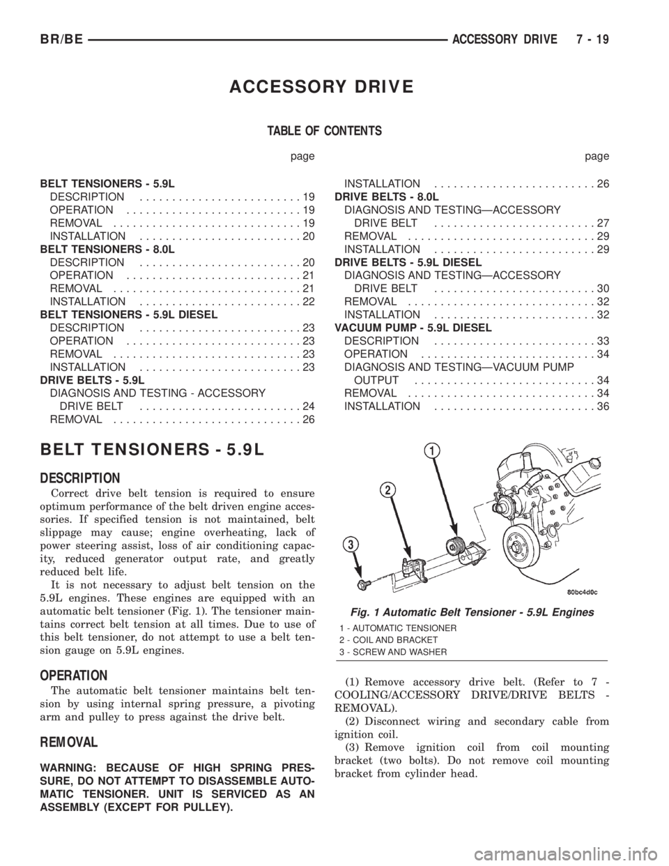
automatic belt tensioner (Fig. 1). The tensioner main-
tains correct belt tension at all times. Due to use of
this belt tensioner, do not attempt to use a belt ten-
sion gauge on 5.9L engines.
OPERATION
The automatic belt tensioner maintains belt ten-
sion by using internal spring pressure, a pivoting
arm and pulley to press against the drive belt.
REMOVAL
WARNING: BECAUSE OF HIGH SPRING PRES-
SURE, DO NOT ATTEMPT TO DISASSEMBLE AUTO-
MATIC TENSIONER. UNIT IS SERVICED AS AN
ASSEMBLY (EXCEPT FOR PULLEY).(1) Remove accessory drive belt. (Refer to 7 -
COOLING/ACCESSORY DRIVE/DRIVE BELTS -
REMOVAL).
(2) Disconnect wiring and secondary cable from
ignition coil.
(3) Remove ignition coil from coil mounting
bracket (two bolts). Do not remove coil mounting
bracket from cylinder head.
Fig. 1 Automatic Belt Tensioner - 5.9L Engines
1 - AUTOMATIC TENSIONER
2 - COIL AND BRACKET
3 - SCREW AND WASHER
BR/BEACCESSORY DRIVE 7 - 19
Page 269 of 2255
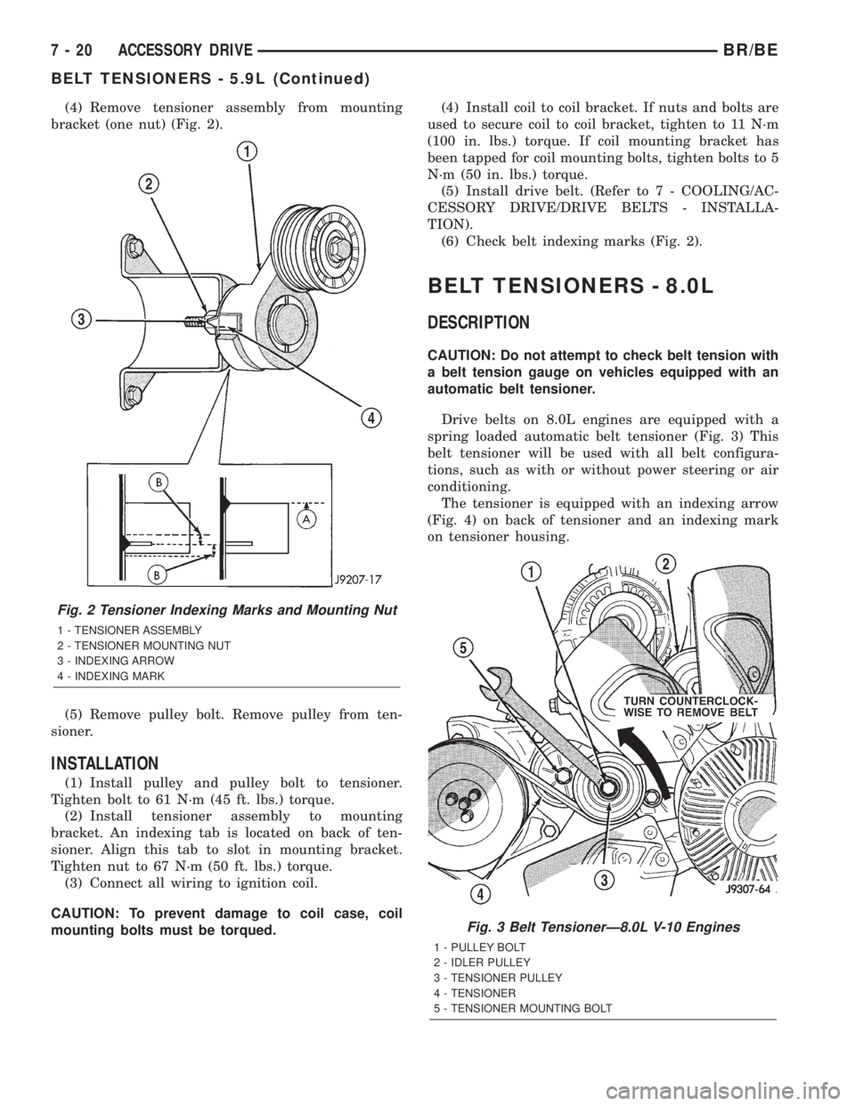
(4) Remove tensioner assembly from mounting
bracket (one nut) (Fig. 2).
(5) Remove pulley bolt. Remove pulley from ten-
sioner.
INSTALLATION
(1) Install pulley and pulley bolt to tensioner.
Tighten bolt to 61 N´m (45 ft. lbs.) torque.
(2) Install tensioner assembly to mounting
bracket. An indexing tab is located on back of ten-
sioner. Align this tab to slot in mounting bracket.
Tighten nut to 67 N´m (50 ft. lbs.) torque.
(3) Connect all wiring to ignition coil.
CAUTION: To prevent damage to coil case, coil
mounting bolts must be torqued.(4) Install coil to coil bracket. If nuts and bolts are
used to secure coil to coil bracket, tighten to 11 N´m
(100 in. lbs.) torque. If coil mounting bracket has
been tapped for coil mounting bolts, tighten bolts to 5
N´m (50 in. lbs.) torque.
(5) Install drive belt. (Refer to 7 - COOLING/AC-
CESSORY DRIVE/DRIVE BELTS - INSTALLA-
TION).
(6) Check belt indexing marks (Fig. 2).
BELT TENSIONERS - 8.0L
DESCRIPTION
CAUTION: Do not attempt to check belt tension with
a belt tension gauge on vehicles equipped with an
automatic belt tensioner.
Drive belts on 8.0L engines are equipped with a
spring loaded automatic belt tensioner (Fig. 3) This
belt tensioner will be used with all belt configura-
tions, such as with or without power steering or air
conditioning.
The tensioner is equipped with an indexing arrow
(Fig. 4) on back of tensioner and an indexing mark
on tensioner housing.
Fig. 2 Tensioner Indexing Marks and Mounting Nut
1 - TENSIONER ASSEMBLY
2 - TENSIONER MOUNTING NUT
3 - INDEXING ARROW
4 - INDEXING MARK
Fig. 3 Belt TensionerÐ8.0L V-10 Engines
1 - PULLEY BOLT
2 - IDLER PULLEY
3 - TENSIONER PULLEY
4 - TENSIONER
5 - TENSIONER MOUNTING BOLT
7 - 20 ACCESSORY DRIVEBR/BE
BELT TENSIONERS - 5.9L (Continued)