2002 DODGE RAM oil
[x] Cancel search: oilPage 1885 of 2255
Condition Possible Cause Correction
Noisy in, or jumps out of, four wheel
drive low range.1) Transfer case not completely
engaged in 4L position.1) With the transmission in
NEUTRAL, or the clutch depressed
in the case of a manual
transmission and the vehicle moving
under 3-4 km/h (2-3 mph), shift the
transfer case to NEUTRAL and then
shift into the 4L position.
2) Shift linkage out of adjustment. 2) Adjust linkage.
3) Shift linkage loose or binding. 3) Tighten, lubricate, or repair
linkage as necessary.
4) Range fork damaged, inserts
worn, or fork is binding on the shift
rail.4) Disassemble unit and repair as
necessary.
5) Low range gear worn or
damaged.5) Disassemble unit and repair as
necessary.
Lubricant leaking from output shaft
seal or vent.1) Transfer case overfilled. 1) Drain lubricant to the correct
level.
2) Vent closed or restricted. 2) Clear or replace vent as
necessary.
3) Output shaft seals damaged or
installed incorrectly.3) Replace seal as necessary.
Check to ensure that another
component, the propeller shaft slip
yoke for example, is not causing
damage to seal.
Abnormal tire wear. 1) Extended operation on hard, dry
surfaces in the 4H position.1) Operate vehicle in the 2H
position on hard, dry surfaces.
REMOVAL
(1) Raise and support vehicle.
(2) Remove skid plate, if equipped. (Refer to 13 -
FRAMES & BUMPERS/FRAME/TRANSFER CASE
SKID PLATE - REMOVAL)
(3) Position drain oil container under transfer
case.
(4) Remove transfer case drain plug and drain
lubricant into container.
(5) Disconnect vent hose and vacuum harness at
transfer case switch.
(6) Disconnect shift rod from grommet in transfer
case shift lever, or from floor shift arm whichever
provides easy access. Use channel lock style pliers to
press rod out of lever grommet.
(7) Support transmission with jack stand.
(8) Remove rear crossmember.
(9) Mark front and rear propeller shafts for assem-
bly reference.(10) Remove front and rear propeller shafts. (Refer
to 3 - DIFFERENTIAL & DRIVELINE/PROPELLER
SHAFT/PROPELLER SHAFT - REMOVAL)
(11) Support transfer case with suitable jack.
Secure transfer case to jack with safety chains.
(12) Remove nuts attaching transfer case to trans-
mission.
(13) Move transfer case assembly rearward until
free of transmission output shaft.
(14) Lower jack and move transfer case from
under vehicle.
DISASSEMBLY
Position transfer case in a shallow drain pan.
Remove drain plug and drain any remaining lubri-
cant remaining in case.
21 - 432 TRANSFER CASE - NV241LDBR/BE
TRANSFER CASE - NV241LD (Continued)
Page 1889 of 2255
(7) Remove rear case and oil pump assembly from
front case.
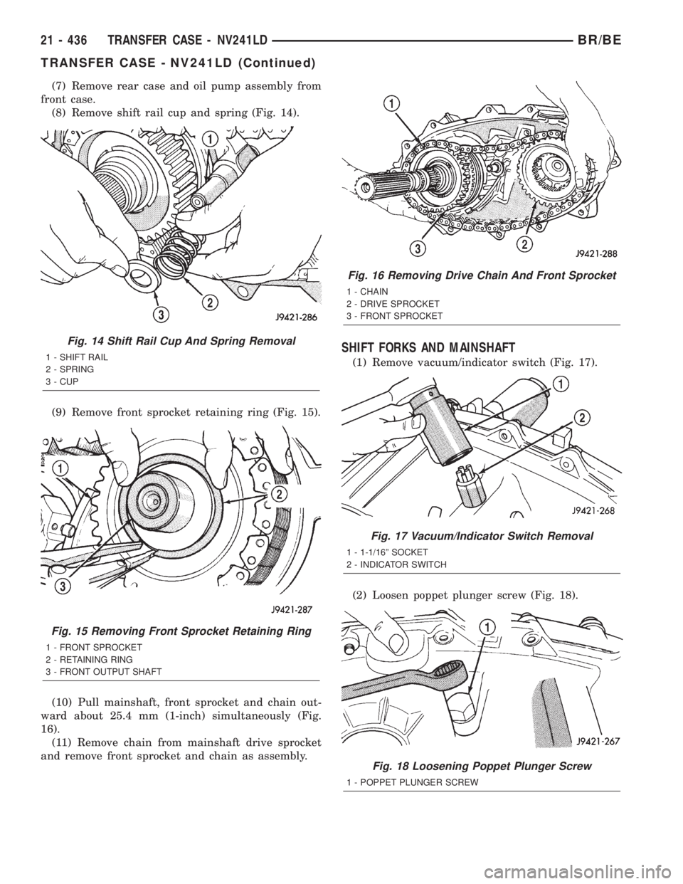
(8) Remove shift rail cup and spring (Fig. 14).
(9) Remove front sprocket retaining ring (Fig. 15).
(10) Pull mainshaft, front sprocket and chain out-
ward about 25.4 mm (1-inch) simultaneously (Fig.
16).
(11) Remove chain from mainshaft drive sprocket
and remove front sprocket and chain as assembly.
SHIFT FORKS AND MAINSHAFT
(1) Remove vacuum/indicator switch (Fig. 17).
(2) Loosen poppet plunger screw (Fig. 18).
Fig. 14 Shift Rail Cup And Spring Removal
1 - SHIFT RAIL
2 - SPRING
3 - CUP
Fig. 15 Removing Front Sprocket Retaining Ring
1 - FRONT SPROCKET
2 - RETAINING RING
3 - FRONT OUTPUT SHAFT
Fig. 16 Removing Drive Chain And Front Sprocket
1 - CHAIN
2 - DRIVE SPROCKET
3 - FRONT SPROCKET
Fig. 17 Vacuum/Indicator Switch Removal
1 - 1-1/16º SOCKET
2 - INDICATOR SWITCH
Fig. 18 Loosening Poppet Plunger Screw
1 - POPPET PLUNGER SCREW
21 - 436 TRANSFER CASE - NV241LDBR/BE
TRANSFER CASE - NV241LD (Continued)
Page 1894 of 2255
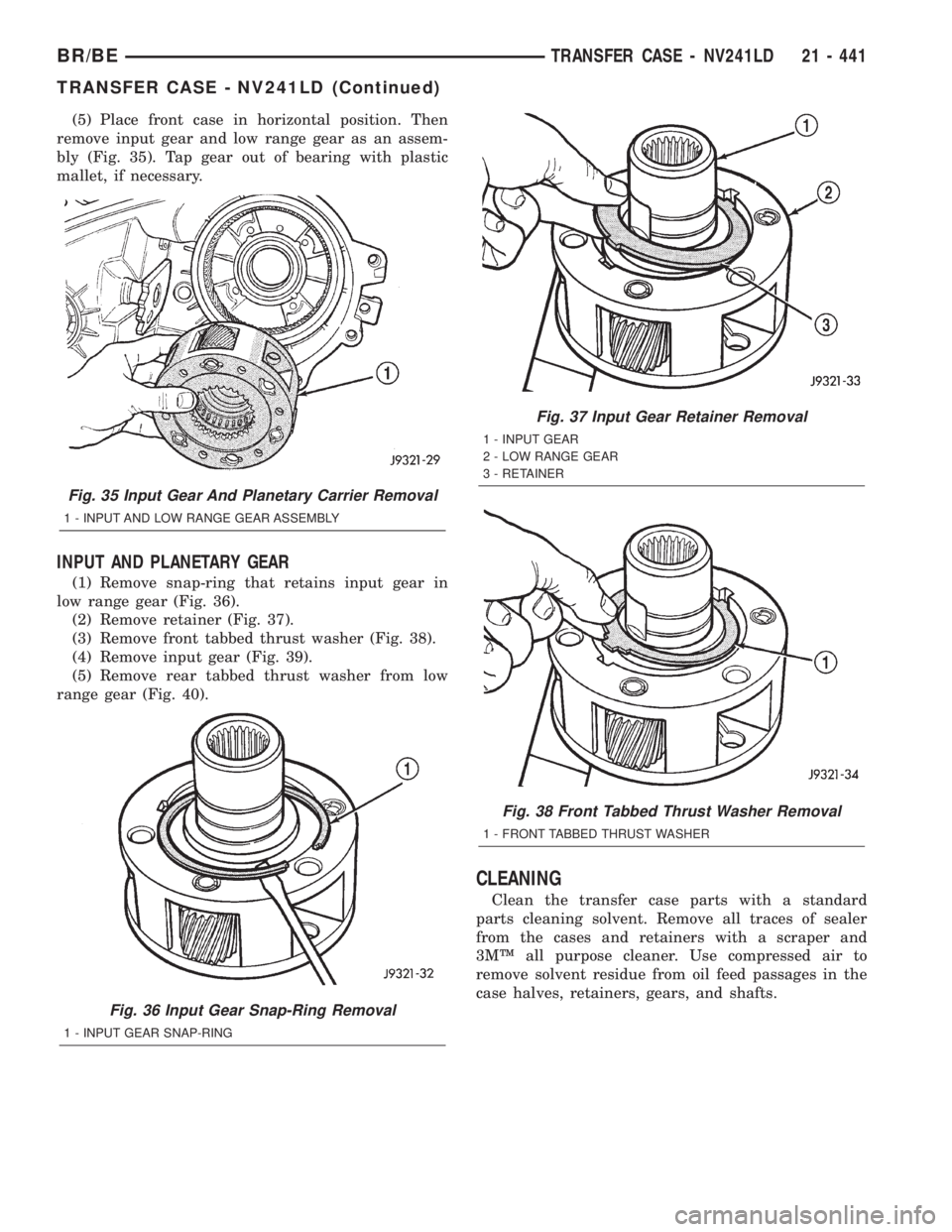
(5) Place front case in horizontal position. Then
remove input gear and low range gear as an assem-
bly (Fig. 35). Tap gear out of bearing with plastic
mallet, if necessary.
INPUT AND PLANETARY GEAR
(1) Remove snap-ring that retains input gear in
low range gear (Fig. 36).
(2) Remove retainer (Fig. 37).
(3) Remove front tabbed thrust washer (Fig. 38).
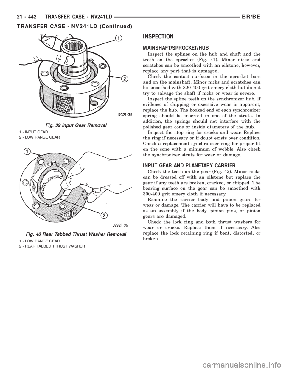
(4) Remove input gear (Fig. 39).
(5) Remove rear tabbed thrust washer from low
range gear (Fig. 40).
CLEANING
Clean the transfer case parts with a standard
parts cleaning solvent. Remove all traces of sealer
from the cases and retainers with a scraper and
3MŸ all purpose cleaner. Use compressed air to
remove solvent residue from oil feed passages in the
case halves, retainers, gears, and shafts.
Fig. 35 Input Gear And Planetary Carrier Removal
1 - INPUT AND LOW RANGE GEAR ASSEMBLY
Fig. 36 Input Gear Snap-Ring Removal
1 - INPUT GEAR SNAP-RING
Fig. 37 Input Gear Retainer Removal
1 - INPUT GEAR
2 - LOW RANGE GEAR
3 - RETAINER
Fig. 38 Front Tabbed Thrust Washer Removal
1 - FRONT TABBED THRUST WASHER
BR/BETRANSFER CASE - NV241LD 21 - 441
TRANSFER CASE - NV241LD (Continued)
Page 1895 of 2255
INSPECTION
MAINSHAFT/SPROCKET/HUB
Inspect the splines on the hub and shaft and the
teeth on the sprocket (Fig. 41). Minor nicks and
scratches can be smoothed with an oilstone, however,
replace any part that is damaged.
Check the contact surfaces in the sprocket bore
and on the mainshaft. Minor nicks and scratches can
be smoothed with 320-400 grit emery cloth but do not
try to salvage the shaft if nicks or wear is severe.
Inspect the spline teeth on the synchronizer hub. If
evidence of chipping or excessive wear is apparent,
replace the hub. The hooked end of each synchronizer
spring should be inserted in one of the struts. In
addition, the springs should not interfere with the
polished gear cone or inside diameters of the hub.
Inspect the stop ring for cracks and wear. Replace
the ring if necessary or if doubt exists over condition.
Check a replacement synchronizer ring for proper fit
on the cone with a minimum of wobble. Also check
the synchronizer struts for wear or damage.
INPUT GEAR AND PLANETARY CARRIER
Check the teeth on the gear (Fig. 42). Minor nicks
can be dressed off with an oilstone but replace the
gear if any teeth are broken, cracked, or chipped. The
bearing surface on the gear can be smoothed with
300-400 grit emery cloth if necessary.
Examine the carrier body and pinion gears for
wear or damage. The carrier will have to be replaced
as an assembly if the body, pinion pins, or pinion
gears are damaged.
Check the lock ring and both thrust washers for
wear or cracks. Replace them if necessary. Also
replace the lock retaining ring if bent, distorted, or
broken.
Fig. 39 Input Gear Removal
1 - INPUT GEAR
2 - LOW RANGE GEAR
Fig. 40 Rear Tabbed Thrust Washer Removal
1 - LOW RANGE GEAR
2 - REAR TABBED THRUST WASHER
21 - 442 TRANSFER CASE - NV241LDBR/BE
TRANSFER CASE - NV241LD (Continued)
Page 1898 of 2255
Or the threads can be repaired with HelicoilŸ stain-
less steel inserts if required.
OIL PUMP/OIL PICKUP
Examine the oil pump pickup parts. Replace the
pump if any part appears to be worn or damaged. Do
not disassemble the pump as individual parts are not
available. The pump is only available as a complete
assembly. The pickup screen, hose, and tube are the
only serviceable parts and are available separately.
ASSEMBLY
BEARINGS AND SEALS
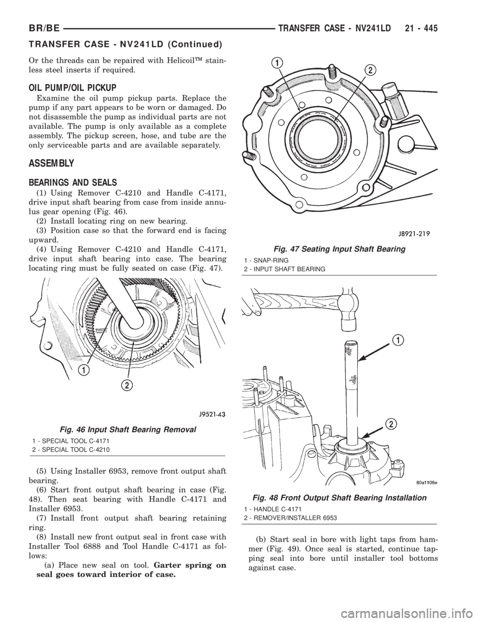
(1) Using Remover C-4210 and Handle C-4171,
drive input shaft bearing from case from inside annu-
lus gear opening (Fig. 46).
(2) Install locating ring on new bearing.
(3) Position case so that the forward end is facing
upward.
(4) Using Remover C-4210 and Handle C-4171,
drive input shaft bearing into case. The bearing
locating ring must be fully seated on case (Fig. 47).
(5) Using Installer 6953, remove front output shaft
bearing.
(6) Start front output shaft bearing in case (Fig.
48). Then seat bearing with Handle C-4171 and
Installer 6953.
(7) Install front output shaft bearing retaining
ring.
(8) Install new front output seal in front case with
Installer Tool 6888 and Tool Handle C-4171 as fol-
lows:
(a) Place new seal on tool.Garter spring on
seal goes toward interior of case.(b) Start seal in bore with light taps from ham-
mer (Fig. 49). Once seal is started, continue tap-
ping seal into bore until installer tool bottoms
against case.
Fig. 46 Input Shaft Bearing Removal
1 - SPECIAL TOOL C-4171
2 - SPECIAL TOOL C-4210
Fig. 47 Seating Input Shaft Bearing
1 - SNAP-RING
2 - INPUT SHAFT BEARING
Fig. 48 Front Output Shaft Bearing Installation
1 - HANDLE C-4171
2 - REMOVER/INSTALLER 6953
BR/BETRANSFER CASE - NV241LD 21 - 445
TRANSFER CASE - NV241LD (Continued)
Page 1899 of 2255
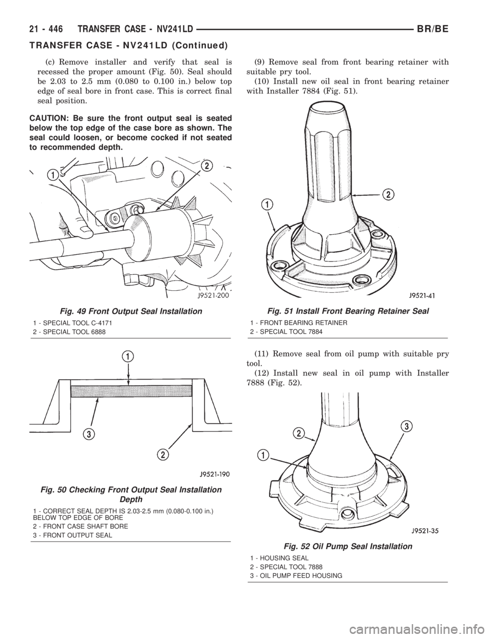
(c) Remove installer and verify that seal is
recessed the proper amount (Fig. 50). Seal should
be 2.03 to 2.5 mm (0.080 to 0.100 in.) below top
edge of seal bore in front case. This is correct final
seal position.
CAUTION: Be sure the front output seal is seated
below the top edge of the case bore as shown. The
seal could loosen, or become cocked if not seated
to recommended depth.(9) Remove seal from front bearing retainer with
suitable pry tool.
(10) Install new oil seal in front bearing retainer
with Installer 7884 (Fig. 51).
(11) Remove seal from oil pump with suitable pry
tool.
(12) Install new seal in oil pump with Installer
7888 (Fig. 52).
Fig. 49 Front Output Seal Installation
1 - SPECIAL TOOL C-4171
2 - SPECIAL TOOL 6888
Fig. 50 Checking Front Output Seal Installation
Depth
1 - CORRECT SEAL DEPTH IS 2.03-2.5 mm (0.080-0.100 in.)
BELOW TOP EDGE OF BORE
2 - FRONT CASE SHAFT BORE
3 - FRONT OUTPUT SEAL
Fig. 51 Install Front Bearing Retainer Seal
1 - FRONT BEARING RETAINER
2 - SPECIAL TOOL 7884
Fig. 52 Oil Pump Seal Installation
1 - HOUSING SEAL
2 - SPECIAL TOOL 7888
3 - OIL PUMP FEED HOUSING
21 - 446 TRANSFER CASE - NV241LDBR/BE
TRANSFER CASE - NV241LD (Continued)
Page 1907 of 2255
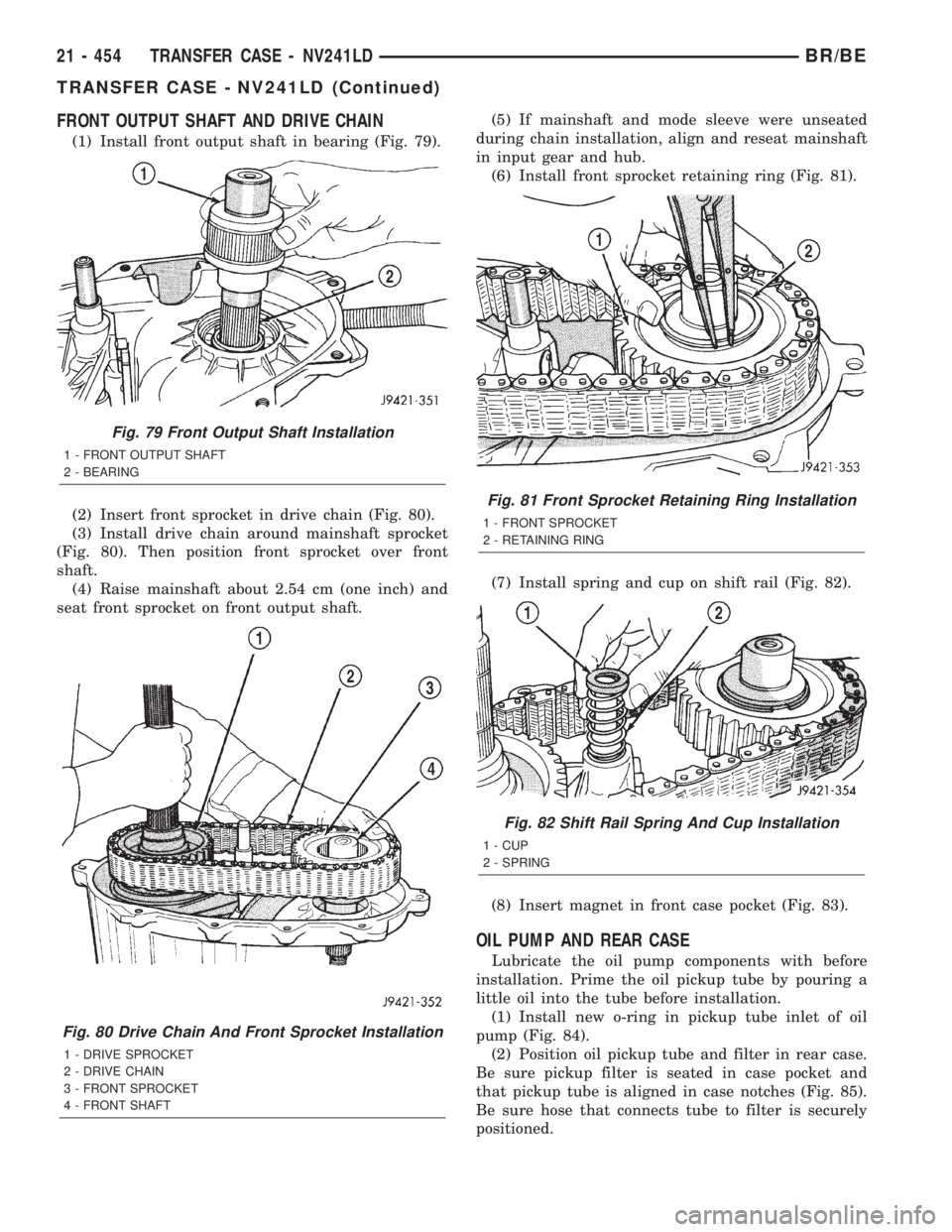
FRONT OUTPUT SHAFT AND DRIVE CHAIN
(1) Install front output shaft in bearing (Fig. 79).
(2) Insert front sprocket in drive chain (Fig. 80).
(3) Install drive chain around mainshaft sprocket
(Fig. 80). Then position front sprocket over front
shaft.
(4) Raise mainshaft about 2.54 cm (one inch) and
seat front sprocket on front output shaft.(5) If mainshaft and mode sleeve were unseated
during chain installation, align and reseat mainshaft
in input gear and hub.
(6) Install front sprocket retaining ring (Fig. 81).
(7) Install spring and cup on shift rail (Fig. 82).
(8) Insert magnet in front case pocket (Fig. 83).
OIL PUMP AND REAR CASE
Lubricate the oil pump components with before
installation. Prime the oil pickup tube by pouring a
little oil into the tube before installation.
(1) Install new o-ring in pickup tube inlet of oil
pump (Fig. 84).
(2) Position oil pickup tube and filter in rear case.
Be sure pickup filter is seated in case pocket and
that pickup tube is aligned in case notches (Fig. 85).
Be sure hose that connects tube to filter is securely
positioned.
Fig. 79 Front Output Shaft Installation
1 - FRONT OUTPUT SHAFT
2 - BEARING
Fig. 80 Drive Chain And Front Sprocket Installation
1 - DRIVE SPROCKET
2 - DRIVE CHAIN
3 - FRONT SPROCKET
4 - FRONT SHAFT
Fig. 81 Front Sprocket Retaining Ring Installation
1 - FRONT SPROCKET
2 - RETAINING RING
Fig. 82 Shift Rail Spring And Cup Installation
1 - CUP
2 - SPRING
21 - 454 TRANSFER CASE - NV241LDBR/BE
TRANSFER CASE - NV241LD (Continued)
Page 1908 of 2255

(3) Insert oil pickup tube in oil pump and position
pump in rear case (Fig. 86).(4) Apply bead of MopartGasket Maker, or equiv-
alent, to mating surface of front case. Keep sealer
bead width to maximum of 3/16 inch. Do not use
excessive amount of sealer as excess will be displaced
into case interior.
(5) Align oil pump with mainshaft and align shift
rail with bore in rear case. Then install rear case and
oil pump assembly (Fig. 87). Be sure oil pump and
pickup tube remain in position during case installa-
tion.
(6) Install 4-5 rear case-to front case bolts to hold
rear case in position. Tighten bolts snug but not to
specified torque at this time.
CAUTION: Verify that shift rail (Fig. 88), and case
alignment dowels are seated before installing any
bolts. Case could be cracked if shaft rail or dowels
are misaligned.
(7) Verify that oil pump is aligned and seated on
rear case. Reposition pump if necessary.
(8) Check stud at end of case halves (Fig. 89). If
stud was loosened or came out during disassembly,
apply LoctiteŸ 242 to stud threads and reseat stud
in case.
(9) Apply LoctiteŸ 242 to remainder of rear case-
to-front case bolt threads and install bolts. Be sure
lock washers are used on studs/bolts at case ends.
Tighten bolts, or stud nuts as follows:
Fig. 83 Case Magnet Installation
1 - MAGNET
2 - CASE POCKET
Fig. 84 Pickup Tube O-Ring Installation
1 - O-RING (PUMP PICKUP)
2 - PICKUP TUBE
Fig. 85 Oil Pickup Tube And Filter Position In Rear
Case
1 - FILTER
2 - TUBE AND HOSE
3 - TUBE IN NOTCH
Fig. 86 Positioning Oil Pump In Rear Case
1 - OIL PUMP
2 - REAR CASE
3 - FILTER
4 - PICKUP TUBE
BR/BETRANSFER CASE - NV241LD 21 - 455
TRANSFER CASE - NV241LD (Continued)