2002 DODGE RAM oil
[x] Cancel search: oilPage 1839 of 2255
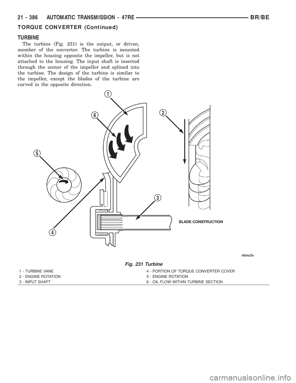
TURBINE
The turbine (Fig. 231) is the output, or driven,
member of the converter. The turbine is mounted
within the housing opposite the impeller, but is not
attached to the housing. The input shaft is inserted
through the center of the impeller and splined into
the turbine. The design of the turbine is similar to
the impeller, except the blades of the turbine are
curved in the opposite direction.
Fig. 231 Turbine
1 - TURBINE VANE 4 - PORTION OF TORQUE CONVERTER COVER
2 - ENGINE ROTATION 5 - ENGINE ROTATION
3 - INPUT SHAFT 6 - OIL FLOW WITHIN TURBINE SECTION
21 - 386 AUTOMATIC TRANSMISSION - 47REBR/BE
TORQUE CONVERTER (Continued)
Page 1840 of 2255
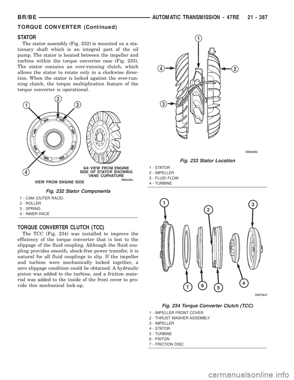
STATOR
The stator assembly (Fig. 232) is mounted on a sta-
tionary shaft which is an integral part of the oil
pump. The stator is located between the impeller and
turbine within the torque converter case (Fig. 233).
The stator contains an over-running clutch, which
allows the stator to rotate only in a clockwise direc-
tion. When the stator is locked against the over-run-
ning clutch, the torque multiplication feature of the
torque converter is operational.
TORQUE CONVERTER CLUTCH (TCC)
The TCC (Fig. 234) was installed to improve the
efficiency of the torque converter that is lost to the
slippage of the fluid coupling. Although the fluid cou-
pling provides smooth, shock-free power transfer, it is
natural for all fluid couplings to slip. If the impeller
and turbine were mechanically locked together, a
zero slippage condition could be obtained. A hydraulic
piston was added to the turbine, and a friction mate-
rial was added to the inside of the front cover to pro-
vide this mechanical lock-up.
Fig. 232 Stator Components
1 - CAM (OUTER RACE)
2 - ROLLER
3 - SPRING
4 - INNER RACE
Fig. 233 Stator Location
1-STATOR
2 - IMPELLER
3 - FLUID FLOW
4 - TURBINE
Fig. 234 Torque Converter Clutch (TCC)
1 - IMPELLER FRONT COVER
2 - THRUST WASHER ASSEMBLY
3 - IMPELLER
4-STATOR
5 - TURBINE
6 - PISTON
7 - FRICTION DISC
BR/BEAUTOMATIC TRANSMISSION - 47RE 21 - 387
TORQUE CONVERTER (Continued)
Page 1842 of 2255
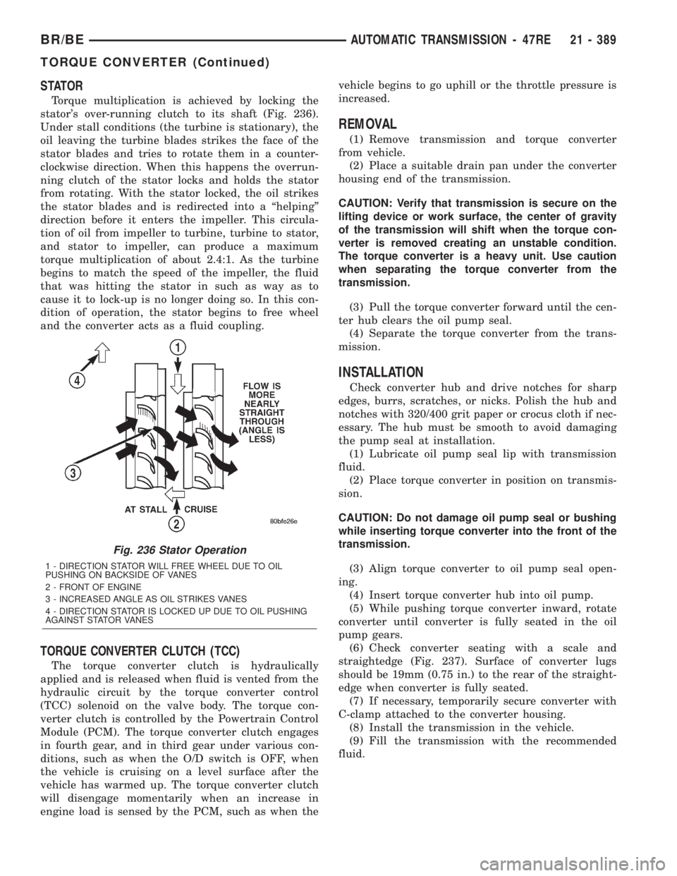
STATOR
Torque multiplication is achieved by locking the
stator's over-running clutch to its shaft (Fig. 236).
Under stall conditions (the turbine is stationary), the
oil leaving the turbine blades strikes the face of the
stator blades and tries to rotate them in a counter-
clockwise direction. When this happens the overrun-
ning clutch of the stator locks and holds the stator
from rotating. With the stator locked, the oil strikes
the stator blades and is redirected into a ªhelpingº
direction before it enters the impeller. This circula-
tion of oil from impeller to turbine, turbine to stator,
and stator to impeller, can produce a maximum
torque multiplication of about 2.4:1. As the turbine
begins to match the speed of the impeller, the fluid
that was hitting the stator in such as way as to
cause it to lock-up is no longer doing so. In this con-
dition of operation, the stator begins to free wheel
and the converter acts as a fluid coupling.
TORQUE CONVERTER CLUTCH (TCC)
The torque converter clutch is hydraulically
applied and is released when fluid is vented from the
hydraulic circuit by the torque converter control
(TCC) solenoid on the valve body. The torque con-
verter clutch is controlled by the Powertrain Control
Module (PCM). The torque converter clutch engages
in fourth gear, and in third gear under various con-
ditions, such as when the O/D switch is OFF, when
the vehicle is cruising on a level surface after the
vehicle has warmed up. The torque converter clutch
will disengage momentarily when an increase in
engine load is sensed by the PCM, such as when thevehicle begins to go uphill or the throttle pressure is
increased.
REMOVAL
(1) Remove transmission and torque converter
from vehicle.
(2) Place a suitable drain pan under the converter
housing end of the transmission.
CAUTION: Verify that transmission is secure on the
lifting device or work surface, the center of gravity
of the transmission will shift when the torque con-
verter is removed creating an unstable condition.
The torque converter is a heavy unit. Use caution
when separating the torque converter from the
transmission.
(3) Pull the torque converter forward until the cen-
ter hub clears the oil pump seal.
(4) Separate the torque converter from the trans-
mission.
INSTALLATION
Check converter hub and drive notches for sharp
edges, burrs, scratches, or nicks. Polish the hub and
notches with 320/400 grit paper or crocus cloth if nec-
essary. The hub must be smooth to avoid damaging
the pump seal at installation.
(1) Lubricate oil pump seal lip with transmission
fluid.
(2) Place torque converter in position on transmis-
sion.
CAUTION: Do not damage oil pump seal or bushing
while inserting torque converter into the front of the
transmission.
(3) Align torque converter to oil pump seal open-
ing.
(4) Insert torque converter hub into oil pump.
(5) While pushing torque converter inward, rotate
converter until converter is fully seated in the oil
pump gears.
(6) Check converter seating with a scale and
straightedge (Fig. 237). Surface of converter lugs
should be 19mm (0.75 in.) to the rear of the straight-
edge when converter is fully seated.
(7) If necessary, temporarily secure converter with
C-clamp attached to the converter housing.
(8) Install the transmission in the vehicle.
(9) Fill the transmission with the recommended
fluid.
Fig. 236 Stator Operation
1 - DIRECTION STATOR WILL FREE WHEEL DUE TO OIL
PUSHING ON BACKSIDE OF VANES
2 - FRONT OF ENGINE
3 - INCREASED ANGLE AS OIL STRIKES VANES
4 - DIRECTION STATOR IS LOCKED UP DUE TO OIL PUSHING
AGAINST STATOR VANES
BR/BEAUTOMATIC TRANSMISSION - 47RE 21 - 389
TORQUE CONVERTER (Continued)
Page 1849 of 2255
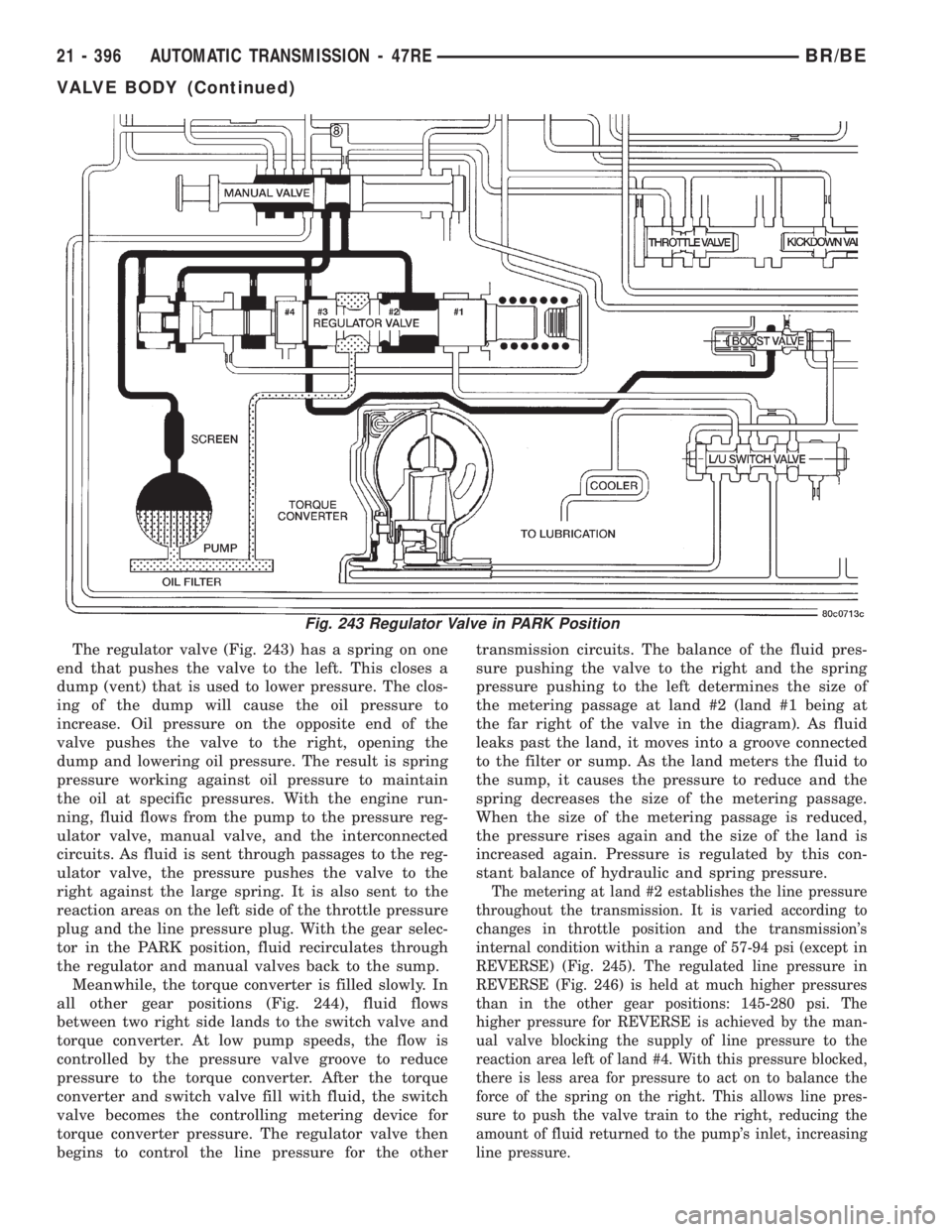
The regulator valve (Fig. 243) has a spring on one
end that pushes the valve to the left. This closes a
dump (vent) that is used to lower pressure. The clos-
ing of the dump will cause the oil pressure to
increase. Oil pressure on the opposite end of the
valve pushes the valve to the right, opening the
dump and lowering oil pressure. The result is spring
pressure working against oil pressure to maintain
the oil at specific pressures. With the engine run-
ning, fluid flows from the pump to the pressure reg-
ulator valve, manual valve, and the interconnected
circuits. As fluid is sent through passages to the reg-
ulator valve, the pressure pushes the valve to the
right against the large spring. It is also sent to the
reaction areas on the left side of the throttle pressure
plug and the line pressure plug. With the gear selec-
tor in the PARK position, fluid recirculates through
the regulator and manual valves back to the sump.
Meanwhile, the torque converter is filled slowly. In
all other gear positions (Fig. 244), fluid flows
between two right side lands to the switch valve and
torque converter. At low pump speeds, the flow is
controlled by the pressure valve groove to reduce
pressure to the torque converter. After the torque
converter and switch valve fill with fluid, the switch
valve becomes the controlling metering device for
torque converter pressure. The regulator valve then
begins to control the line pressure for the othertransmission circuits. The balance of the fluid pres-
sure pushing the valve to the right and the spring
pressure pushing to the left determines the size of
the metering passage at land #2 (land #1 being at
the far right of the valve in the diagram). As fluid
leaks past the land, it moves into a groove connected
to the filter or sump. As the land meters the fluid to
the sump, it causes the pressure to reduce and the
spring decreases the size of the metering passage.
When the size of the metering passage is reduced,
the pressure rises again and the size of the land is
increased again. Pressure is regulated by this con-
stant balance of hydraulic and spring pressure.
The metering at land #2 establishes the line pressure
throughout the transmission. It is varied according to
changes in throttle position and the transmission's
internal condition within a range of 57-94 psi (except in
REVERSE) (Fig. 245). The regulated line pressure in
REVERSE (Fig. 246) is held at much higher pressures
than in the other gear positions: 145-280 psi. The
higher pressure for REVERSE is achieved by the man-
ual valve blocking the supply of line pressure to the
reaction area left of land #4. With this pressure blocked,
there is less area for pressure to act on to balance the
force of the spring on the right. This allows line pres-
sure to push the valve train to the right, reducing the
amount of fluid returned to the pump's inlet, increasing
line pressure.
Fig. 243 Regulator Valve in PARK Position
21 - 396 AUTOMATIC TRANSMISSION - 47REBR/BE
VALVE BODY (Continued)
Page 1858 of 2255
The higher engine speed and line pressure would
open the vent too far and reduce line pressure too
much. Throttle pressure, which increases with engine
speed (throttle opening), is used to oppose the move-
ment of the pressure valve to help control the meter-
ing passage at the vent. The throttle pressure is
combined with spring pressure to reduce the force of
the throttle pressure plug on the pressure valve. The
larger spring at the right closes the regulator valve
passage and maintains or increases line pressure.
The increased line pressure works against the reac-
tion area of the line pressure plug and the reaction
area left of land #3 simultaneously moves the regu-
lator valve train to the right and controls the meter-
ing passage.
The kickdown valve, along with the throttle valve,
serve to delay upshifts until the correct vehicle speed
has been reached. It also controls downshifts upon
driver demand, or increased engine load. If these
valves were not in place, the shift points would be at
the same speed for all throttle positions. The kick-
down valve is actuated by a cam connected to the
throttle. This is accomplished through either a link-
age or a cable. The cam forces the kickdown valve
toward the throttle valve compressing the spring
between them and moving the throttle valve. As the
throttle valve land starts to uncover its port, line
pressure is ªmeteredº out into the circuits and viewed
as throttle pressure. This increased throttle pressure
is metered out into the circuits it is applied to: the
1-2 and 2-3 shift valves. When the throttle pressure
is high enough, a 3-2 downshift will occur. If the
vehicle speed is low enough, a 2-1 downshift will
occur.
SWITCH VALVE
When the transmission is in Drive Second before
the TCC application occurs (Fig. 258), the pressure
regulator valve is supplying torque converter pres-
sure to the switch valve. The switch valve directs
this pressure through the transmission input shaft,
into the converter, through the converter, back out
between the input shaft and the reaction shaft, and
back up to the switch valve. From the switch valve,
the fluid pressure is directed to the transmission
cooler, and lubrication pressure returns from the
cooler to lubricate different portions of the transmis-
sion.Once the TCC control valve has moved to the right
(Fig. 259), line pressure is directed to the tip of the
switch valve, forcing the valve to the right. The
switch valve now vents oil from the front of the pis-
ton in the torque converter, and supplies line pres-
sure to the (rear) apply side of the torque converter
piston. This pressure differential causes the piston to
apply against the friction material, cutting off any
further flow of line pressure oil. After the switch
valve is shuttled right allowing line pressure to
engage the TCC, torque converter pressure is
directed past the switch valve into the transmission
cooler and lubrication circuits.
MANUAL VALVE
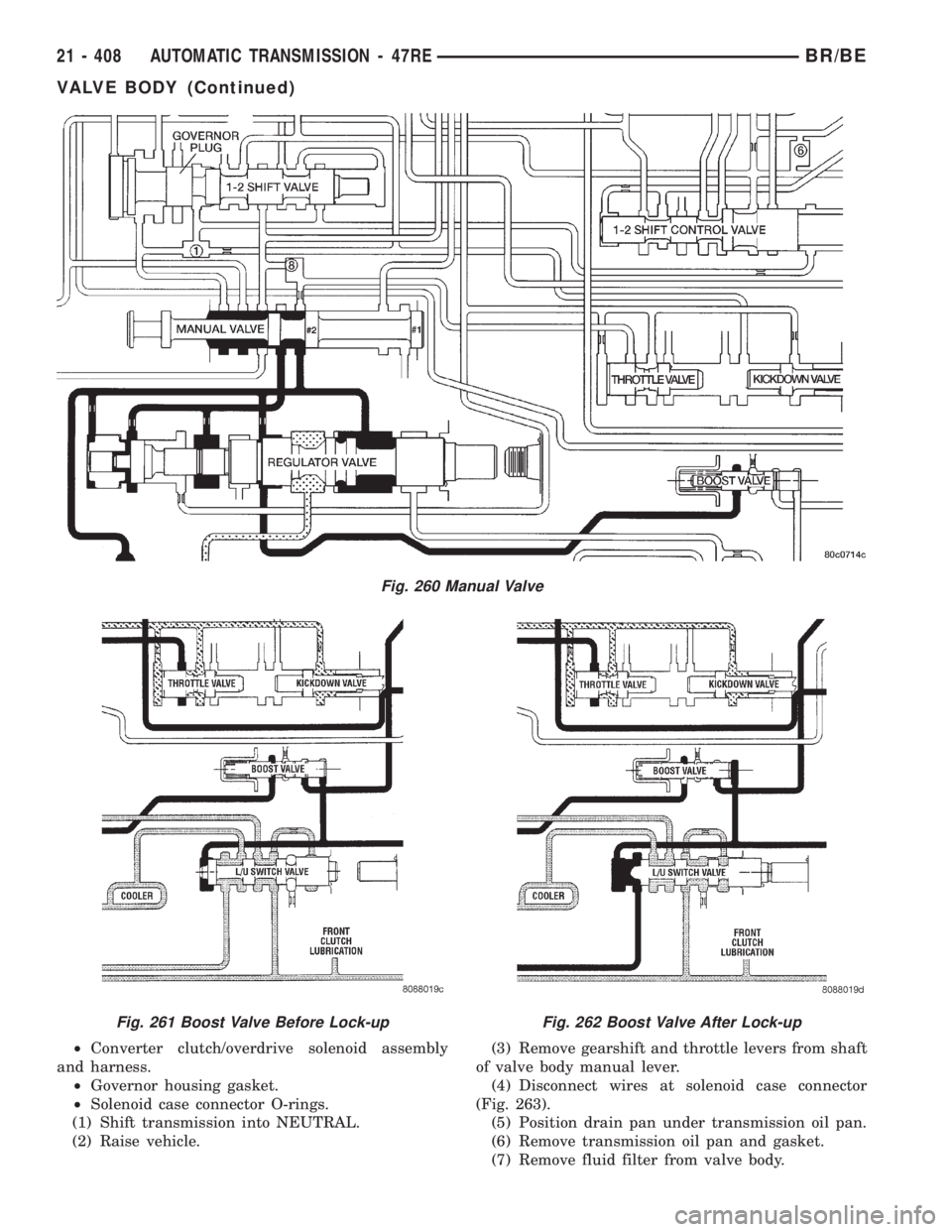
The manual valve (Fig. 260) is a relay valve. The
purpose of the manual valve is to direct fluid to the
correct circuit needed for a specific gear or driving
range. The manual valve, as the name implies, is
manually operated by the driver with a lever located
on the side of the valve body. The valve is connected
mechanically by either a cable or linkage to the gear-
shift mechanism. The valve is held in each of its
positions by a spring-loaded roller or ball that
engages the ªroostercombº of the manual valve lever.
CONVERTER CLUTCH LOCK-UP VALVE
The torque converter clutch (TCC) lock-up valve
controls the back (ON) side of the torque converter
clutch. When the PCM energizes the TCC solenoid to
engage the converter clutch piston, pressure is
applied to the TCC lock-up valve which moves to the
right and applies pressure to the torque converter
clutch.
CONVERTER CLUTCH LOCK-UP TIMING VALVE
The torque converter clutch (TCC) lock-up timing
valve is there to block any 4-3 downshift until the
TCC is completely unlocked and the clutch is disen-
gaged.
BR/BEAUTOMATIC TRANSMISSION - 47RE 21 - 405
VALVE BODY (Continued)
Page 1861 of 2255
²Converter clutch/overdrive solenoid assembly
and harness.
²Governor housing gasket.
²Solenoid case connector O-rings.
(1) Shift transmission into NEUTRAL.
(2) Raise vehicle.(3) Remove gearshift and throttle levers from shaft
of valve body manual lever.
(4) Disconnect wires at solenoid case connector
(Fig. 263).
(5) Position drain pan under transmission oil pan.
(6) Remove transmission oil pan and gasket.
(7) Remove fluid filter from valve body.
Fig. 260 Manual Valve
Fig. 261 Boost Valve Before Lock-upFig. 262 Boost Valve After Lock-up
21 - 408 AUTOMATIC TRANSMISSION - 47REBR/BE
VALVE BODY (Continued)
Page 1873 of 2255
CAUTION: Many of the valves and plugs, such as
the throttle valve, shuttle valve plug, 1-2 shift valve
and 1-2 governor plug, are made of coated alumi-
num. Aluminum components are identified by the
dark color of the special coating applied to the sur-
face (or by testing with a magnet). Do not sand alu-
minum valves or plugs under any circumstances.
This practice could damage the special coating
causing the valves/plugs to stick and bind.
Inspect the valves and plugs for scratches, burrs,
nicks, or scores. Minor surface scratches on steel
valves and plugs can be removed with crocus cloth
butdo not round off the edges of the valve or
plug lands.Maintaining sharpness of these edges is
vitally important. The edges prevent foreign matter
from lodging between the valves and plugs and the
bore.
Inspect all the valve and plug bores in the valve
body. Use a penlight to view the bore interiors.
Replace the valve body if any bores are distorted or
scored. Inspect all of the valve body springs. The
springs must be free of distortion, warpage or broken
coils.
Check the two separator plates for distortion or
damage of any kind. Inspect the upper housing,
lower housing, 3-4 accumulator housing, and transfer
plate carefully. Be sure all fluid passages are clean
and clear. Check condition of the upper housing andtransfer plate check balls as well. The check balls
and ball seats must not be worn or damaged.
Trial fit each valve and plug in its bore to check
freedom of operation. When clean and dry, the valves
and plugs should drop freely into the bores.
Valve body bores do not change dimensionally with
use. If the valve body functioned correctly when new,
it will continue to operate properly after cleaning and
inspection. It should not be necessary to replace a
valve body assembly unless it is damaged in han-
dling.
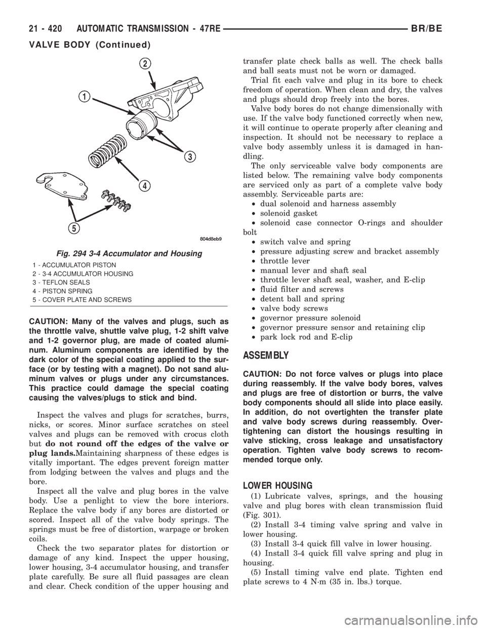
The only serviceable valve body components are
listed below. The remaining valve body components
are serviced only as part of a complete valve body
assembly. Serviceable parts are:
²dual solenoid and harness assembly
²solenoid gasket
²solenoid case connector O-rings and shoulder
bolt
²switch valve and spring
²pressure adjusting screw and bracket assembly
²throttle lever
²manual lever and shaft seal
²throttle lever shaft seal, washer, and E-clip
²fluid filter and screws
²detent ball and spring
²valve body screws
²governor pressure solenoid
²governor pressure sensor and retaining clip
²park lock rod and E-clip
ASSEMBLY
CAUTION: Do not force valves or plugs into place
during reassembly. If the valve body bores, valves
and plugs are free of distortion or burrs, the valve
body components should all slide into place easily.
In addition, do not overtighten the transfer plate
and valve body screws during reassembly. Over-
tightening can distort the housings resulting in
valve sticking, cross leakage and unsatisfactory
operation. Tighten valve body screws to recom-
mended torque only.
LOWER HOUSING
(1) Lubricate valves, springs, and the housing
valve and plug bores with clean transmission fluid
(Fig. 301).
(2) Install 3-4 timing valve spring and valve in
lower housing.
(3) Install 3-4 quick fill valve in lower housing.
(4) Install 3-4 quick fill valve spring and plug in
housing.
(5) Install timing valve end plate. Tighten end
plate screws to 4 N´m (35 in. lbs.) torque.
Fig. 294 3-4 Accumulator and Housing
1 - ACCUMULATOR PISTON
2 - 3-4 ACCUMULATOR HOUSING
3 - TEFLON SEALS
4 - PISTON SPRING
5 - COVER PLATE AND SCREWS
21 - 420 AUTOMATIC TRANSMISSION - 47REBR/BE
VALVE BODY (Continued)
Page 1881 of 2255
(9) Connect harness wires to governor pressure
solenoid and governor pressure sensor.
(10) Install fluid filter and pan.
(11) Lower vehicle.
(12) Fill transmission with recommended fluid and
road test vehicle to verify repair.
INSTALLATION
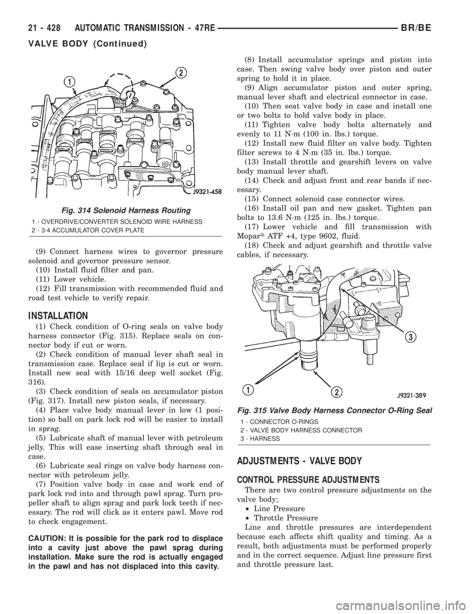
(1) Check condition of O-ring seals on valve body
harness connector (Fig. 315). Replace seals on con-
nector body if cut or worn.
(2) Check condition of manual lever shaft seal in
transmission case. Replace seal if lip is cut or worn.
Install new seal with 15/16 deep well socket (Fig.
316).
(3) Check condition of seals on accumulator piston
(Fig. 317). Install new piston seals, if necessary.
(4) Place valve body manual lever in low (1 posi-
tion) so ball on park lock rod will be easier to install
in sprag.
(5) Lubricate shaft of manual lever with petroleum
jelly. This will ease inserting shaft through seal in
case.
(6) Lubricate seal rings on valve body harness con-
nector with petroleum jelly.
(7) Position valve body in case and work end of
park lock rod into and through pawl sprag. Turn pro-
peller shaft to align sprag and park lock teeth if nec-
essary. The rod will click as it enters pawl. Move rod
to check engagement.
CAUTION: It is possible for the park rod to displace
into a cavity just above the pawl sprag during
installation. Make sure the rod is actually engaged
in the pawl and has not displaced into this cavity.(8) Install accumulator springs and piston into
case. Then swing valve body over piston and outer
spring to hold it in place.
(9) Align accumulator piston and outer spring,
manual lever shaft and electrical connector in case.
(10) Then seat valve body in case and install one
or two bolts to hold valve body in place.
(11) Tighten valve body bolts alternately and
evenly to 11 N´m (100 in. lbs.) torque.
(12) Install new fluid filter on valve body. Tighten
filter screws to 4 N´m (35 in. lbs.) torque.
(13) Install throttle and gearshift levers on valve
body manual lever shaft.
(14) Check and adjust front and rear bands if nec-
essary.
(15) Connect solenoid case connector wires.
(16) Install oil pan and new gasket. Tighten pan
bolts to 13.6 N´m (125 in. lbs.) torque.
(17) Lower vehicle and fill transmission with
MopartATF +4, type 9602, fluid.
(18) Check and adjust gearshift and throttle valve
cables, if necessary.
ADJUSTMENTS - VALVE BODY
CONTROL PRESSURE ADJUSTMENTS
There are two control pressure adjustments on the
valve body;
²Line Pressure
²Throttle Pressure
Line and throttle pressures are interdependent
because each affects shift quality and timing. As a
result, both adjustments must be performed properly
and in the correct sequence. Adjust line pressure first
and throttle pressure last.
Fig. 314 Solenoid Harness Routing
1 - OVERDRIVE/CONVERTER SOLENOID WIRE HARNESS
2 - 3-4 ACCUMULATOR COVER PLATE
Fig. 315 Valve Body Harness Connector O-Ring Seal
1 - CONNECTOR O-RINGS
2 - VALVE BODY HARNESS CONNECTOR
3 - HARNESS
21 - 428 AUTOMATIC TRANSMISSION - 47REBR/BE
VALVE BODY (Continued)