2002 DODGE RAM oil
[x] Cancel search: oilPage 1938 of 2255
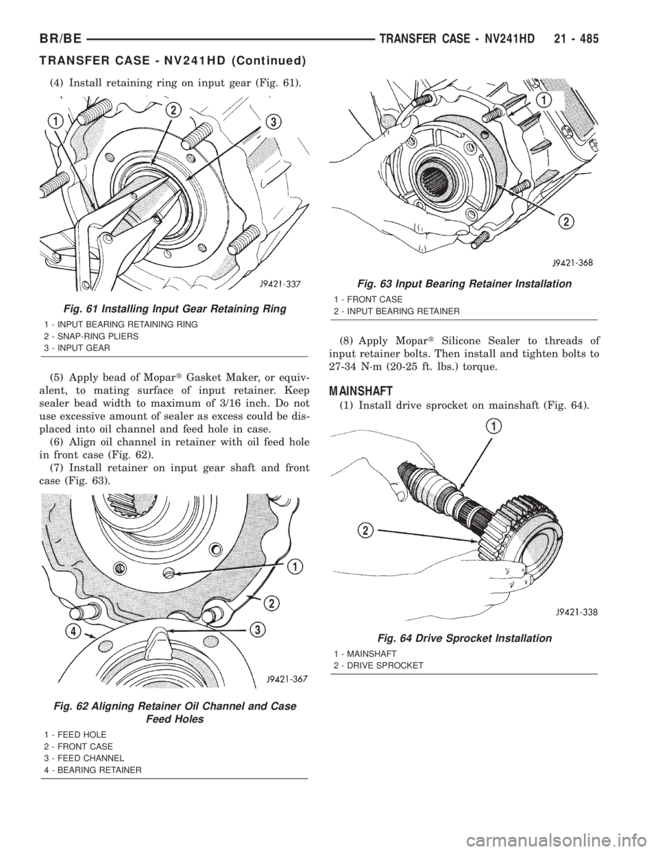
(4) Install retaining ring on input gear (Fig. 61).
(5) Apply bead of MopartGasket Maker, or equiv-
alent, to mating surface of input retainer. Keep
sealer bead width to maximum of 3/16 inch. Do not
use excessive amount of sealer as excess could be dis-
placed into oil channel and feed hole in case.
(6) Align oil channel in retainer with oil feed hole
in front case (Fig. 62).
(7) Install retainer on input gear shaft and front
case (Fig. 63).(8) Apply MopartSilicone Sealer to threads of
input retainer bolts. Then install and tighten bolts to
27-34 N´m (20-25 ft. lbs.) torque.
MAINSHAFT
(1) Install drive sprocket on mainshaft (Fig. 64).
Fig. 61 Installing Input Gear Retaining Ring
1 - INPUT BEARING RETAINING RING
2 - SNAP-RING PLIERS
3 - INPUT GEAR
Fig. 62 Aligning Retainer Oil Channel and Case
Feed Holes
1 - FEED HOLE
2 - FRONT CASE
3 - FEED CHANNEL
4 - BEARING RETAINER
Fig. 63 Input Bearing Retainer Installation
1 - FRONT CASE
2 - INPUT BEARING RETAINER
Fig. 64 Drive Sprocket Installation
1 - MAINSHAFT
2 - DRIVE SPROCKET
BR/BETRANSFER CASE - NV241HD 21 - 485
TRANSFER CASE - NV241HD (Continued)
Page 1945 of 2255
(7) Realign sliding clutch on synchronizer hub if
necessary. Press synchronizer struts inward to ease
realignment. Be sure mainshaft is fully seated before
proceeding.
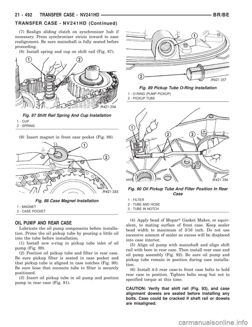
(8) Install spring and cup on shift rail (Fig. 87).
(9) Insert magnet in front case pocket (Fig. 88).
OIL PUMP AND REAR CASE
Lubricate the oil pump components before installa-
tion. Prime the oil pickup tube by pouring a little oil
into the tube before installation.
(1) Install new o-ring in pickup tube inlet of oil
pump (Fig. 89).
(2) Position oil pickup tube and filter in rear case.
Be sure pickup filter is seated in case pocket and
that pickup tube is aligned in case notches (Fig. 90).
Be sure hose that connects tube to filter is securely
positioned.
(3) Insert oil pickup tube in oil pump and position
pump in rear case (Fig. 91).(4) Apply bead of MopartGasket Maker, or equiv-
alent, to mating surface of front case. Keep sealer
bead width to maximum of 3/16 inch. Do not use
excessive amount of sealer as excess will be displaced
into case interior.
(5) Align oil pump with mainshaft and align shift
rail with bore in rear case. Then install rear case and
oil pump assembly (Fig. 92). Be sure oil pump and
pickup tube remain in position during case installa-
tion.
(6) Install 4-5 rear case-to front case bolts to hold
rear case in position. Tighten bolts snug but not to
specified torque at this time.
CAUTION: Verify that shift rail (Fig. 93), and case
alignment dowels are seated before installing any
bolts. Case could be cracked if shaft rail or dowels
are misaligned.
Fig. 87 Shift Rail Spring And Cup Installation
1 - CUP
2 - SPRING
Fig. 88 Case Magnet Installation
1 - MAGNET
2 - CASE POCKET
Fig. 89 Pickup Tube O-Ring Installation
1 - O-RING (PUMP PICKUP)
2 - PICKUP TUBE
Fig. 90 Oil Pickup Tube And Filter Position In Rear
Case
1 - FILTER
2 - TUBE AND HOSE
3 - TUBE IN NOTCH
21 - 492 TRANSFER CASE - NV241HDBR/BE
TRANSFER CASE - NV241HD (Continued)
Page 1946 of 2255
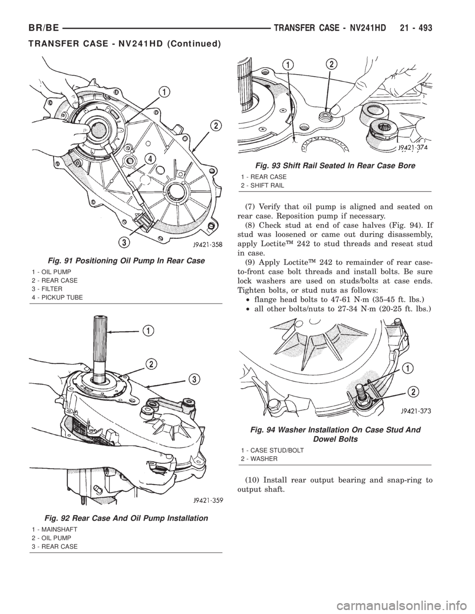
(7) Verify that oil pump is aligned and seated on
rear case. Reposition pump if necessary.
(8) Check stud at end of case halves (Fig. 94). If
stud was loosened or came out during disassembly,
apply LoctiteŸ 242 to stud threads and reseat stud
in case.
(9) Apply LoctiteŸ 242 to remainder of rear case-
to-front case bolt threads and install bolts. Be sure
lock washers are used on studs/bolts at case ends.
Tighten bolts, or stud nuts as follows:
²flange head bolts to 47-61 N´m (35-45 ft. lbs.)
²all other bolts/nuts to 27-34 N´m (20-25 ft. lbs.)
(10) Install rear output bearing and snap-ring to
output shaft.
Fig. 91 Positioning Oil Pump In Rear Case
1 - OIL PUMP
2 - REAR CASE
3 - FILTER
4 - PICKUP TUBE
Fig. 92 Rear Case And Oil Pump Installation
1 - MAINSHAFT
2 - OIL PUMP
3 - REAR CASE
Fig. 93 Shift Rail Seated In Rear Case Bore
1 - REAR CASE
2 - SHIFT RAIL
Fig. 94 Washer Installation On Case Stud And
Dowel Bolts
1 - CASE STUD/BOLT
2 - WASHER
BR/BETRANSFER CASE - NV241HD 21 - 493
TRANSFER CASE - NV241HD (Continued)
Page 1947 of 2255
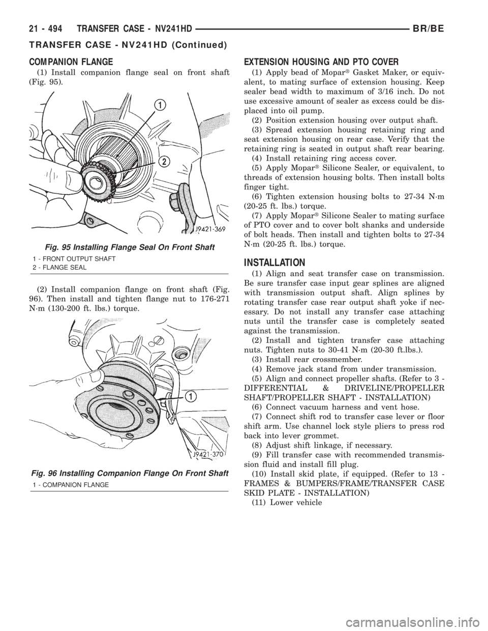
COMPANION FLANGE
(1) Install companion flange seal on front shaft
(Fig. 95).
(2) Install companion flange on front shaft (Fig.
96). Then install and tighten flange nut to 176-271
N´m (130-200 ft. lbs.) torque.
EXTENSION HOUSING AND PTO COVER
(1) Apply bead of MopartGasket Maker, or equiv-
alent, to mating surface of extension housing. Keep
sealer bead width to maximum of 3/16 inch. Do not
use excessive amount of sealer as excess could be dis-
placed into oil pump.
(2) Position extension housing over output shaft.
(3) Spread extension housing retaining ring and
seat extension housing on rear case. Verify that the
retaining ring is seated in output shaft rear bearing.
(4) Install retaining ring access cover.
(5) Apply MopartSilicone Sealer, or equivalent, to
threads of extension housing bolts. Then install bolts
finger tight.
(6) Tighten extension housing bolts to 27-34 N´m
(20-25 ft. lbs.) torque.
(7) Apply MopartSilicone Sealer to mating surface
of PTO cover and to cover bolt shanks and underside
of bolt heads. Then install and tighten bolts to 27-34
N´m (20-25 ft. lbs.) torque.
INSTALLATION
(1) Align and seat transfer case on transmission.
Be sure transfer case input gear splines are aligned
with transmission output shaft. Align splines by
rotating transfer case rear output shaft yoke if nec-
essary. Do not install any transfer case attaching
nuts until the transfer case is completely seated
against the transmission.
(2) Install and tighten transfer case attaching
nuts. Tighten nuts to 30-41 N´m (20-30 ft.lbs.).
(3) Install rear crossmember.
(4) Remove jack stand from under transmission.
(5) Align and connect propeller shafts. (Refer to 3 -
DIFFERENTIAL & DRIVELINE/PROPELLER
SHAFT/PROPELLER SHAFT - INSTALLATION)
(6) Connect vacuum harness and vent hose.
(7) Connect shift rod to transfer case lever or floor
shift arm. Use channel lock style pliers to press rod
back into lever grommet.
(8) Adjust shift linkage, if necessary.
(9) Fill transfer case with recommended transmis-
sion fluid and install fill plug.
(10) Install skid plate, if equipped. (Refer to 13 -
FRAMES & BUMPERS/FRAME/TRANSFER CASE
SKID PLATE - INSTALLATION)
(11) Lower vehicle
Fig. 95 Installing Flange Seal On Front Shaft
1 - FRONT OUTPUT SHAFT
2 - FLANGE SEAL
Fig. 96 Installing Companion Flange On Front Shaft
1 - COMPANION FLANGE
21 - 494 TRANSFER CASE - NV241HDBR/BE
TRANSFER CASE - NV241HD (Continued)
Page 1948 of 2255
SPECIFICATIONS
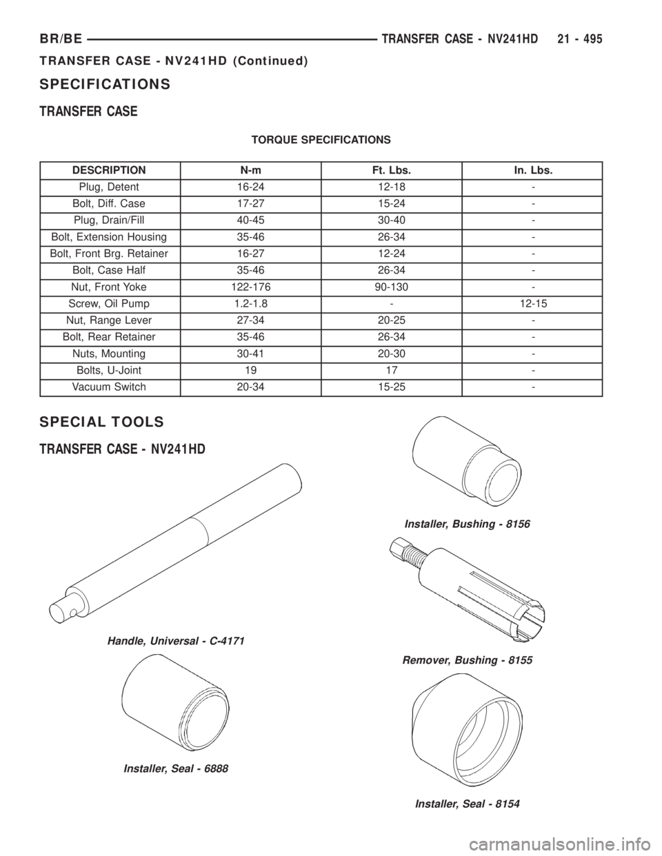
TRANSFER CASE
TORQUE SPECIFICATIONS
DESCRIPTION N-m Ft. Lbs. In. Lbs.
Plug, Detent 16-24 12-18 -
Bolt, Diff. Case 17-27 15-24 -
Plug, Drain/Fill 40-45 30-40 -
Bolt, Extension Housing 35-46 26-34 -
Bolt, Front Brg. Retainer 16-27 12-24 -
Bolt, Case Half 35-46 26-34 -
Nut, Front Yoke 122-176 90-130 -
Screw, Oil Pump 1.2-1.8 - 12-15
Nut, Range Lever 27-34 20-25 -
Bolt, Rear Retainer 35-46 26-34 -
Nuts, Mounting 30-41 20-30 -
Bolts, U-Joint 19 17 -
Vacuum Switch 20-34 15-25 -
SPECIAL TOOLS
TRANSFER CASE - NV241HD
Handle, Universal - C-4171
Installer, Seal - 6888
Installer, Bushing - 8156
Remover, Bushing - 8155
Installer, Seal - 8154
BR/BETRANSFER CASE - NV241HD 21 - 495
TRANSFER CASE - NV241HD (Continued)
Page 1966 of 2255
DIAGNOSIS AND TESTING
WHEEL INSPECTION
Inspect wheels for:
²Excessive run out
²Dents or cracks
²Damaged wheel lug nut holes
²Air Leaks from any area or surface of the rim
NOTE: Do not attempt to repair a wheel by hammer-
ing, heating or welding.
If a wheel is damaged an original equipment
replacement wheel should be used. When obtaining
replacement wheels, they should be equivalent in
load carrying capacity. The diameter, width, offset,
pilot hole and bolt circle of the wheel should be the
same as the original wheel.
WARNING: FAILURE TO USE EQUIVALENT REPLACE-
MENT WHEELS MAY ADVERSELY AFFECT THE
SAFETY AND HANDLING OF THE VEHICLE. USED
WHEELS ARE NOT RECOMMENDED. THE SERVICE
HISTORY OF THE WHEEL MAY HAVE INCLUDED
SEVERE TREATMENT OR VERY HIGH MILEAGE. THE
RIM COULD FAIL WITHOUT WARNING.
STANDARD PROCEDURE - DUAL REAR WHEEL
INSTALLATION
Dual rear wheels use a special heavy duty lug nut
wrench. It is recommended to remove and install dual
rear wheels only when the proper wrench is available.
The wrench is also use to remove wheel center caps for
more information refer to Owner's Manual.
The tires on both wheels must be completely raised
off the ground when tightening the lug nuts. This
will ensure correct wheel centering and maximum
wheel clamping.
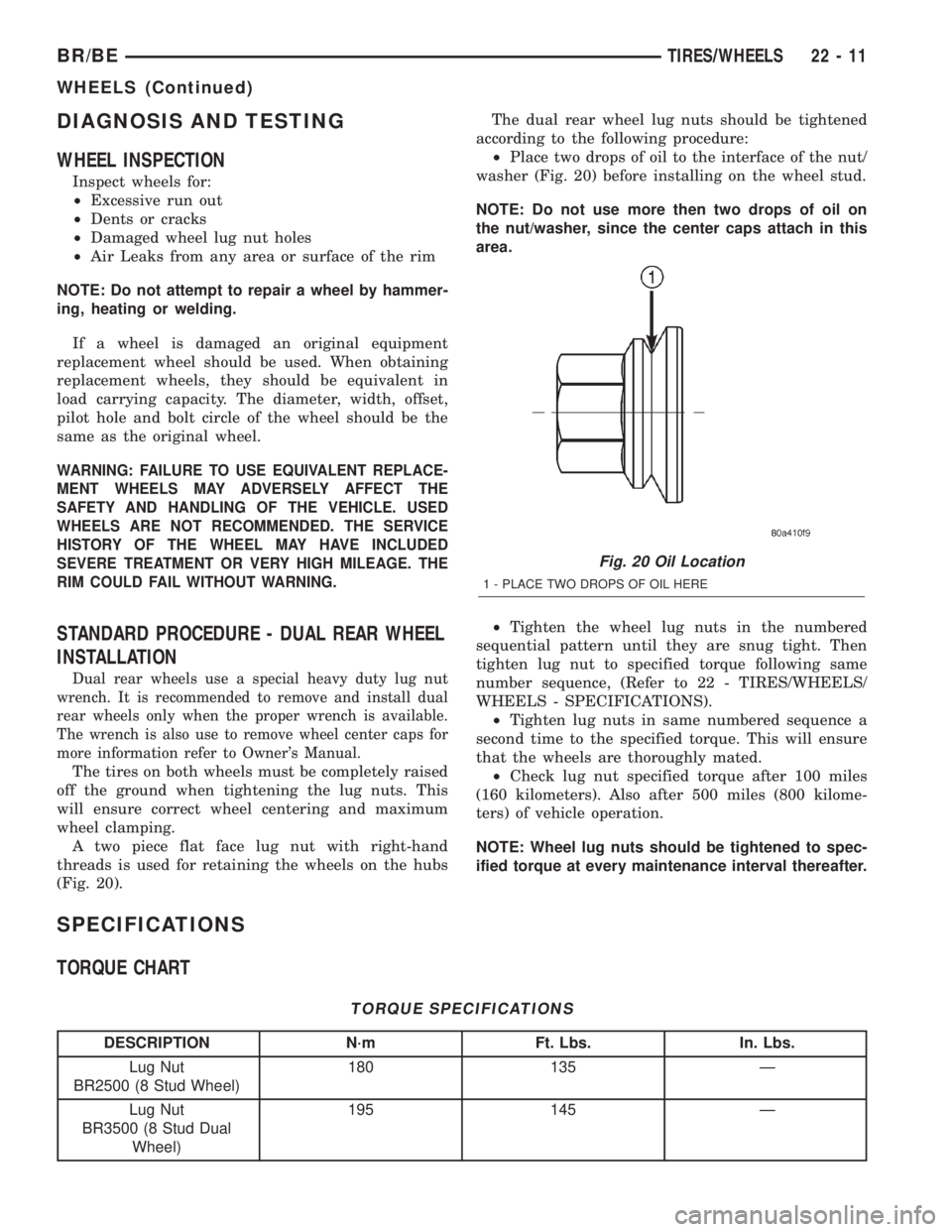
A two piece flat face lug nut with right-hand
threads is used for retaining the wheels on the hubs
(Fig. 20).The dual rear wheel lug nuts should be tightened
according to the following procedure:
²Place two drops of oil to the interface of the nut/
washer (Fig. 20) before installing on the wheel stud.
NOTE: Do not use more then two drops of oil on
the nut/washer, since the center caps attach in this
area.
²Tighten the wheel lug nuts in the numbered
sequential pattern until they are snug tight. Then
tighten lug nut to specified torque following same
number sequence, (Refer to 22 - TIRES/WHEELS/
WHEELS - SPECIFICATIONS).
²Tighten lug nuts in same numbered sequence a
second time to the specified torque. This will ensure
that the wheels are thoroughly mated.
²Check lug nut specified torque after 100 miles
(160 kilometers). Also after 500 miles (800 kilome-
ters) of vehicle operation.
NOTE: Wheel lug nuts should be tightened to spec-
ified torque at every maintenance interval thereafter.
SPECIFICATIONS
TORQUE CHART
TORQUE SPECIFICATIONS
DESCRIPTION N´m Ft. Lbs. In. Lbs.
Lug Nut
BR2500 (8 Stud Wheel)180 135 Ð
Lug Nut
BR3500 (8 Stud Dual
Wheel)195 145 Ð
Fig. 20 Oil Location
1 - PLACE TWO DROPS OF OIL HERE
BR/BETIRES/WHEELS 22 - 11
WHEELS (Continued)
Page 2097 of 2255
PAINT TOUCH-UP
DESCRIPTION
When a painted metal surface has been scratched
or chipped, it should be touched-up as soon as possi-
ble to avoid corrosion. For best results, use Mopart
Scratch Filler/Primer, Touch-Up Paints and Clear Top
Coat. Refer to Introduction group of this manual for
Body Code Plate information.
WARNING: USE AN OSHA APPROVED BREATHING
FILTER WHEN SPRAYING PAINT OR SOLVENTS IN
A CONFINED AREA. PERSONAL INJURY CAN
RESULT.
OPERATION
(1) Scrape loose paint and corrosion from inside
scratch or chip.
(2) Clean affected area with MopartTar/Road Oil
Remover, and allow to dry.
(3) Fill the inside of the scratch or chip with a coat
of filler/primer. Do not overlap primer onto good sur-
face finish. The applicator brush should be wet
enough to puddle-fill the defect without running. Do
not stroke brush applicator on body surface. Allow
the filler/primer to dry hard.
(4) Cover the filler/primer with color touch-up
paint. Do not overlap touch-up color onto the original
color coat around the scratch or chip. Butt the new
color to the original color, if possible. Do not stroke
applicator brush on body surface. Allow touch-up
paint to dry hard.(5) On vehicles without clear coat, the touch-up
color can be lightly finesse sanded (1500 grit) and
polished with rubbing compound.
(6) On vehicles with clear coat, apply clear top coat
to touch-up paint with the same technique as
described in Step 4. Allow clear top coat to dry hard.
If desired, Step 5 can be performed on clear top coat.
WARNING: AVOID PROLONGED SKIN CONTACT
WITH PETROLEUM OR ALCOHOL ± BASED CLEAN-
ING SOLVENTS. PERSONAL INJURY CAN RESULT.
AVOID PROLONGED SKIN CONTACT WITH PETRO-
LEUM OR ALCOHOL ± BASED CLEANING SOL-
VENTS. PERSONAL INJURY CAN RESULT.WET SANDING/BUFFING &
POLISHING
DESCRIPTION
Minor acid etching, orange peel, or smudging in
clear coat or single-stage finishes can be reduced
with light finesse sanding, hand buffing, and polish-
ing.If the finish has been finesse sanded in the
past, it cannot be repeated. Finesse sanding
operation should be performed by a trained
automotive paint technician.
CAUTION: Do not remove clear coat finish, if
equipped. Base coat paint must retain clear coat for
durability.
23 - 130 PAINTBR/BE
Page 2113 of 2255
(2) If necessary, apply black-out primer to outer
edge of replacement backlite frame.
(3) If black-out primer was pre-applied on backlite,
clean bonding surface with Isopropyl alcohol and
clean lint free cloth. Allow 3 minutes for drying time.
(4) Apply black-out primer to backlite opening
fence.
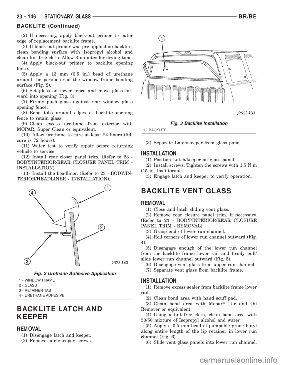
(5) Apply a 13 mm (0.5 in.) bead of urethane
around the perimeter of the window frame bonding
surface (Fig. 2).
(6) Set glass on lower fence and move glass for-
ward into opening (Fig. 3).
(7) Firmly push glass against rear window glass
opening fence.
(8) Bend tabs around edges of backlite opening
fence to retain glass.
(9) Clean excess urethane from exterior with
MOPAR, Super Clean or equivalent.
(10) Allow urethane to cure at least 24 hours (full
cure is 72 hours).
(11) Water test to verify repair before returning
vehicle to service.
(12) Install rear closer panel trim. (Refer to 23 -
BODY/INTERIOR/REAR CLOSURE PANEL TRIM -
INSTALLATION).
(13) Install the headliner. (Refer to 23 - BODY/IN-
TERIOR/HEADLINER - INSTALLATION).
BACKLITE LATCH AND
KEEPER
REMOVAL
(1) Disengage latch and keeper.
(2) Remove latch/keeper screws.(3) Separate Latch/keeper from glass panel.
INSTALLATION
(1) Position Latch/keeper on glass panel.
(2) Install screws. Tighten the screws with 1.5 N´m
(15 in. lbs.) torque.
(3) Engage latch and keeper to verify operation.
BACKLITE VENT GLASS
REMOVAL
(1) Close and latch sliding vent glass.
(2) Remove rear closure panel trim, if necessary.
(Refer to 23 - BODY/INTERIOR/REAR CLOSURE
PANEL TRIM - REMOVAL).
(3) Grasp end of lower run channel.
(4) Roll corners of lower run channel outward (Fig.
4).
(5) Disengage enough of the lower run channel
from the backlite frame lower rail and firmly pull/
slide lower run channel outward (Fig. 5).
(6) Disengage vent glass from upper run channel.
(7) Separate vent glass from backlite frame.
INSTALLATION
(1) Remove excess sealer from backlite frame lower
rail.
(2) Clean bond area with hand scuff pad.
(3) Clean bond area with MopartTar and Oil
Remover or equivalent.
(4) Using a lint free cloth, clean bond area with
50/50 mixture of Isopropyl alcohol and water.
(5) Apply a 0.5 mm bead of pumpable grade butyl
along entire length of the lip retainer in lower run
channel (Fig. 6).
(6) Slide vent glass panels into lower run channel.
Fig. 2 Urethane Adhesive Application
1 - WINDOW FRAME
2 - GLASS
3 - RETAINER TAB
4 - URETHANE ADHESIVE
Fig. 3 Backlite Installation
1 - BACKLITE
23 - 146 STATIONARY GLASSBR/BE
BACKLITE (Continued)