2002 DODGE RAM maintenance
[x] Cancel search: maintenancePage 1254 of 2255
(3) Always check the condition of the used oil. This
can give you an indication of engine problems that
might exist.
²Thin, black oil indicates fuel dilution.
²Milky discoloration indicates coolant dilution.
(4) Clean the area around the oil filter head.
Remove the filter (Refer to 9 - ENGINE/LUBRICA-
TION/OIL FILTER - REMOVAL).
(5) Install new oil filter (Refer to 9 - ENGINE/LU-
BRICATION/OIL FILTER - INSTALLATION).
(6) Clean the drain plug and the sealing surface of
the pan. Check the condition of the threads and seal-
ing surface on the oil pan and drain plug.
(7) Install the drain plug. Tighten the plug to 50
N´m (37 ft. lbs.) torque.
(8) Use only High-Quality Multi-Viscosity lubricat-
ing oil in the Cummins Turbo Diesel engine. Choose
the correct oil for the operating conditions (Refer to
LUBRICATION & MAINTENANCE/FLUID TYPES -
DESCRIPTION).
(9) Fill the engine with the correct grade of new oil
(Refer to LUBRICATION & MAINTENANCE/FLUID
CAPACITIES - SPECIFICATIONS).
(10) Start the engine and operate it at idle for sev-
eral minutes. Check for leaks at the filter and drain
plug.
(11) Stop engine. Wait several minutes to allow the
oil to drain back to the pan and check the level
again.
USED ENGINE OIL DISPOSAL Care should be
exercised when disposing of used engine oil after
it has been drained from a vehicle's engine.
OIL COOLER & LINES
CLEANING AND INSPECTION
Clean the sealing surfaces.
Apply 483 kPa (70 psi) air pressure to the element
to check for leaks. If the element leaks, replace the
element.
OIL FILTER
REMOVAL
(1) Clean the area around the oil filter head.
Remove the filter using a 90-95 mm filter wrench.
(2) Clean the gasket surface of the filter head. The
filter canister O-Ring seal can stick on the filter
head. Make sure it is removed.
INSTALLATION
(1) Fill the oil filter element with clean oil before
installation. Use the same type oil that will be used
in the engine.
(2) Apply a light film of lubricating oil to the seal-
ing surface before installing the filter.
CAUTION: Mechanical over-tightening may distort
the threads or damage the filter element seal.
(3) Install the filter until it contacts the sealing
surface of the oil filter adapter. Tighten filter an
additional ó turn.
OIL PAN
REMOVAL
(1) Disconnect the battery negative cables.
(2) Raise vehicle on hoist.
(3) Remove transmission and transfer case (if
equipped).
(4) Remove flywheel.
(5) Disconnect starter cables from starter motor.
(6) Remove starter motor (Refer to 8 - ELECTRI-
CAL/STARTING/STARTER MOTOR - REMOVAL)
and transmission adapter plate assembly.
WARNING: HOT OIL CAN CAUSE PERSONAL
INJURY.
(7) Drain the engine oil (Refer to 9 - ENGINE/LU-
BRICATION/OIL - STANDARD PROCEDURE).
(8) Install the oil pan drain plug with a new seal-
ing washer and tighten to 60 N´m (44 ft. lbs.) torque.
(9) Remove oil pan bolts, break the pan to block
seal, and lower pan slightly and remove oil suction
tube fasteners.
(10) Remove oil pan and suction tube (Fig. 151).
CLEANING
Remove all gasket material from the oil pan and
cylinder block sealing surfaces. Extra effort may be
required around T-joint areas. Clean oil pan and
flush suction tube with a suitable solvent.
INSPECTION
Inspect the oil pan, suction tube, and tube braces
for cracks and damage. Replace any defective compo-
nent. Inspect the oil drain plug and drain hole
threads. Inspect the oil pan sealing surface for
straightness. Repair any minor imperfections with a
ball-peen hammer. Do not attempt to repair an oil
pan by welding.
BR/BEENGINE 5.9L DIESEL 9 - 179
OIL (Continued)
Page 1301 of 2255
FUEL DELIVERY - GASOLINE
DESCRIPTION - FUEL DELIVERY SYSTEM
The fuel delivery system consists of:
²the fuel pump module containing the electric
fuel pump, fuel filter/fuel pressure regulator, rollover
valve (certain modules), fuel gauge sending unit (fuel
level sensor) and a separate fuel filter located at bot-
tom of pump module
²fuel tubes/lines/hoses
²quick-connect fittings
²fuel injector rail
²fuel injectors
²fuel tank
²fuel tank filler/vent tube assembly
²fuel tank filler tube cap
²accelerator pedal
²throttle cable
OPERATION - FUEL DELIVERY SYSTEM
Fuel is returned through the fuel pump module
and back into the fuel tank through the fuel filter/
fuel pressure regulator. A separate fuel return line
from the engine to the tank is not used with any gas-
oline powered engine.
The fuel tank assembly consists of: the fuel tank,
fuel pump module assembly, fuel pump module lock-
nut/gasket and fuel tank check valve(s) (refer to 25,
Emission Control System for Fuel Tank Check Valve
information).
A fuel filler/vent tube assembly using a pressure/
vacuum, 1/4 turn fuel filler cap is used. The fuel
filler tube contains a flap door located below the fuel
fill cap.
Also to be considered part of the fuel system is the
evaporation control system. This is designed to
reduce the emission of fuel vapors into the atmo-
sphere. The description and function of the Evapora-
tive Control System is found in 25, Emission Control
Systems.
Both fuel filters (at bottom of fuel pump module
and within fuel pressure regulator) are designed for
extended service. They do not require normal sched-
uled maintenance. Filters should only be replaced if
a diagnostic procedure indicates to do so.
DIAGNOSIS AND TESTING - FUEL PRESSURE
LEAK DOWN TEST
Use this test in conjunction with the Fuel Pump
Pressure Test and Fuel Pump Capacity Test.
Check Valve Operation:The electric fuel pump
outlet contains a one-way check valve to prevent fuel
flow back into the tank and to maintain fuel supply
line pressure (engine warm) when pump is not oper-
ational. It is also used to keep the fuel supply linefull of gasoline when pump is not operational. After
the vehicle has cooled down, fuel pressure may drop
to 0 psi (cold fluid contracts), but liquid gasoline will
remain in fuel supply line between the check valve
and fuel injectors.Fuel pressure that has
dropped to 0 psi on a cooled down vehicle
(engine off) is a normal condition.When the elec-
tric fuel pump is activated, fuel pressure should
immediately(1±2 seconds) rise to specification.
Abnormally long periods of cranking to restart a
hotengine that has been shut down for a short
period of time may be caused by:
²Fuel pressure bleeding past a fuel injector(s).
²Fuel pressure bleeding past the check valve in
the fuel pump module.
(1) Disconnect the fuel inlet line at fuel rail. Refer
to Fuel Tubes/Lines/Hoses and Clamps for proce-
dures. On some engines, air cleaner housing removal
may be necessary before fuel line disconnection.
(2) Obtain correct Fuel Line Pressure Test Adapter
Tool Hose. Tool number 6539 is used for 5/16º fuel
lines and tool number 6631 is used for 3/8º fuel lines.
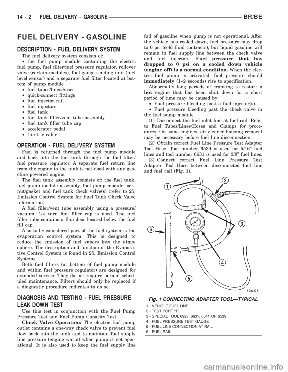
(3) Connect correct Fuel Line Pressure Test
Adapter Tool Hose between disconnected fuel line
and fuel rail (Fig. 1).
Fig. 1 CONNECTING ADAPTER TOOLÐTYPICAL
1 - VEHICLE FUEL LINE
2 - TEST PORT ªTº
3 - SPECIAL TOOL 6923, 6631, 6541 OR 6539
4 - FUEL PRESSURE TEST GAUGE
5 - FUEL LINE CONNECTION AT RAIL
6 - FUEL RAIL
14 - 2 FUEL DELIVERY - GASOLINEBR/BE
Page 1304 of 2255
FUEL FILTER/PRESSURE
REGULATOR
DESCRIPTION
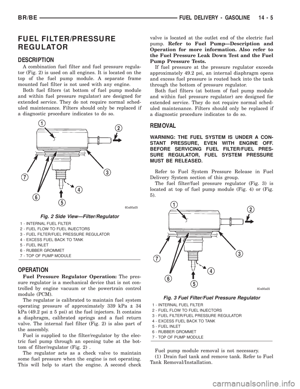
A combination fuel filter and fuel pressure regula-
tor (Fig. 2) is used on all engines. It is located on the
top of the fuel pump module. A separate frame
mounted fuel filter is not used with any engine.
Both fuel filters (at bottom of fuel pump module
and within fuel pressure regulator) are designed for
extended service. They do not require normal sched-
uled maintenance. Filters should only be replaced if
a diagnostic procedure indicates to do so.
OPERATION
Fuel Pressure Regulator Operation:The pres-
sure regulator is a mechanical device that is not con-
trolled by engine vacuum or the powertrain control
module (PCM).
The regulator is calibrated to maintain fuel system
operating pressure of approximately 339 kPa 34
kPa (49.2 psi 5 psi) at the fuel injectors. It contains
a diaphragm, calibrated springs and a fuel return
valve. The internal fuel filter (Fig. 2) is also part of
the assembly.
Fuel is supplied to the filter/regulator by the elec-
tric fuel pump through an opening tube at the bot-
tom of filter/regulator (Fig. 2) .
The regulator acts as a check valve to maintain
some fuel pressure when the engine is not operating.
This will help to start the engine. A second checkvalve is located at the outlet end of the electric fuel
pump.Refer to Fuel PumpÐDescription and
Operation for more information. Also refer to
the Fuel Pressure Leak Down Test and the Fuel
Pump Pressure Tests.
If fuel pressure at the pressure regulator exceeds
approximately 49.2 psi, an internal diaphragm opens
and excess fuel pressure is routed back into the tank
through the bottom of pressure regulator.
Both fuel filters (at bottom of fuel pump module
and within fuel pressure regulator) are designed for
extended service. They do not require normal sched-
uled maintenance. Filters should only be replaced if
a diagnostic procedure indicates to do so.
REMOVAL
WARNING: THE FUEL SYSTEM IS UNDER A CON-
STANT PRESSURE, EVEN WITH ENGINE OFF.
BEFORE SERVICING FUEL FILTER/FUEL PRES-
SURE REGULATOR, FUEL SYSTEM PRESSURE
MUST BE RELEASED.
Refer to Fuel System Pressure Release in Fuel
Delivery System section of this group.
The fuel filter/fuel pressure regulator (Fig. 3) is
located at top of fuel pump module (Fig. 4) or (Fig.
5).
Fuel pump module removal is not necessary.
(1) Drain fuel tank and remove tank. Refer to Fuel
Tank Removal/Installation.
Fig. 2 Side ViewÐFilter/Regulator
1 - INTERNAL FUEL FILTER
2 - FUEL FLOW TO FUEL INJECTORS
3 - FUEL FILTER/FUEL PRESSURE REGULATOR
4 - EXCESS FUEL BACK TO TANK
5 - FUEL INLET
6 - RUBBER GROMMET
7 - TOP OF PUMP MODULE
Fig. 3 Fuel Filter/Fuel Pressure Regulator
1 - INTERNAL FUEL FILTER
2 - FUEL FLOW TO FUEL INJECTORS
3 - FUEL FILTER/FUEL PRESSURE REGULATOR
4 - EXCESS FUEL BACK TO TANK
5 - FUEL INLET
6 - RUBBER GROMMET
7 - TOP OF PUMP MODULE
BR/BEFUEL DELIVERY - GASOLINE 14 - 5
Page 1362 of 2255
SPECIAL TOOLS
DIESEL FUEL SYSTEMFUEL FILTER / WATER
SEPARATOR
DESCRIPTION
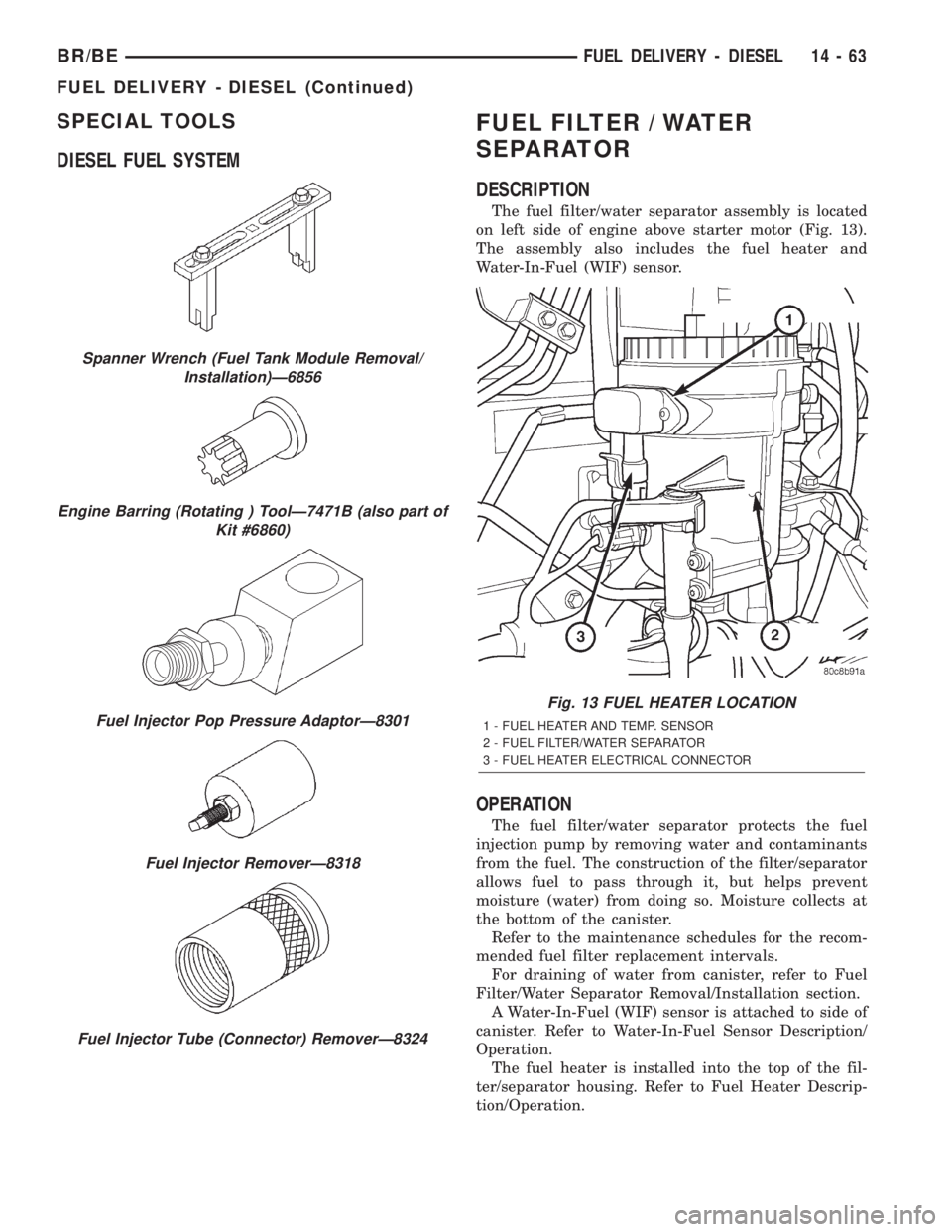
The fuel filter/water separator assembly is located
on left side of engine above starter motor (Fig. 13).
The assembly also includes the fuel heater and
Water-In-Fuel (WIF) sensor.
OPERATION
The fuel filter/water separator protects the fuel
injection pump by removing water and contaminants
from the fuel. The construction of the filter/separator
allows fuel to pass through it, but helps prevent
moisture (water) from doing so. Moisture collects at
the bottom of the canister.
Refer to the maintenance schedules for the recom-
mended fuel filter replacement intervals.
For draining of water from canister, refer to Fuel
Filter/Water Separator Removal/Installation section.
A Water-In-Fuel (WIF) sensor is attached to side of
canister. Refer to Water-In-Fuel Sensor Description/
Operation.
The fuel heater is installed into the top of the fil-
ter/separator housing. Refer to Fuel Heater Descrip-
tion/Operation.
Spanner Wrench (Fuel Tank Module Removal/
Installation)Ð6856
Engine Barring (Rotating ) ToolÐ7471B (also part of
Kit #6860)
Fuel Injector Pop Pressure AdaptorÐ8301
Fuel Injector RemoverÐ8318
Fuel Injector Tube (Connector) RemoverÐ8324
Fig. 13 FUEL HEATER LOCATION
1 - FUEL HEATER AND TEMP. SENSOR
2 - FUEL FILTER/WATER SEPARATOR
3 - FUEL HEATER ELECTRICAL CONNECTOR
BR/BEFUEL DELIVERY - DIESEL 14 - 63
FUEL DELIVERY - DIESEL (Continued)
Page 1363 of 2255
REMOVAL
Refer to maintenance schedules in this manual for
recommended fuel filter replacement intervals.
Draining water from fuel filter/water separa-
tor housing:
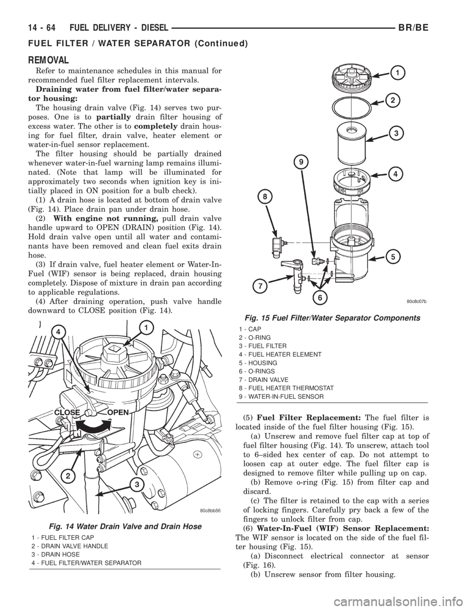
The housing drain valve (Fig. 14) serves two pur-
poses. One is topartiallydrain filter housing of
excess water. The other is tocompletelydrain hous-
ing for fuel filter, drain valve, heater element or
water-in-fuel sensor replacement.
The filter housing should be partially drained
whenever water-in-fuel warning lamp remains illumi-
nated. (Note that lamp will be illuminated for
approximately two seconds when ignition key is ini-
tially placed in ON position for a bulb check).
(1) A drain hose is located at bottom of drain valve
(Fig. 14). Place drain pan under drain hose.
(2)With engine not running,pull drain valve
handle upward to OPEN (DRAIN) position (Fig. 14).
Hold drain valve open until all water and contami-
nants have been removed and clean fuel exits drain
hose.
(3) If drain valve, fuel heater element or Water-In-
Fuel (WIF) sensor is being replaced, drain housing
completely. Dispose of mixture in drain pan according
to applicable regulations.
(4) After draining operation, push valve handle
downward to CLOSE position (Fig. 14).
(5)Fuel Filter Replacement:The fuel filter is
located inside of the fuel filter housing (Fig. 15).
(a) Unscrew and remove fuel filter cap at top of
fuel filter housing (Fig. 14). To unscrew, attach tool
to 6±sided hex center of cap. Do not attempt to
loosen cap at outer edge. The fuel filter cap is
designed to remove filter while pulling up on cap.
(b) Remove o-ring (Fig. 15) from filter cap and
discard.
(c) The filter is retained to the cap with a series
of locking fingers. Carefully pry back a few of the
fingers to unlock filter from cap.
(6)Water-In-Fuel (WIF) Sensor Replacement:
The WIF sensor is located on the side of the fuel fil-
ter housing (Fig. 15).
(a) Disconnect electrical connector at sensor
(Fig. 16).
(b) Unscrew sensor from filter housing.
Fig. 14 Water Drain Valve and Drain Hose
1 - FUEL FILTER CAP
2 - DRAIN VALVE HANDLE
3 - DRAIN HOSE
4 - FUEL FILTER/WATER SEPARATOR
Fig. 15 Fuel Filter/Water Separator Components
1 - CAP
2 - O-RING
3 - FUEL FILTER
4 - FUEL HEATER ELEMENT
5 - HOUSING
6 - O-RINGS
7 - DRAIN VALVE
8 - FUEL HEATER THERMOSTAT
9 - WATER-IN-FUEL SENSOR
14 - 64 FUEL DELIVERY - DIESELBR/BE
FUEL FILTER / WATER SEPARATOR (Continued)
Page 1364 of 2255
(c) Check condition of o-ring.
(d) Inspect the 2 WIF sensor probes. Carefully
clean contaminants from sensor probes with a cloth
if necessary. Replace sensor if probes are covered
with contaminants and will not clean up.
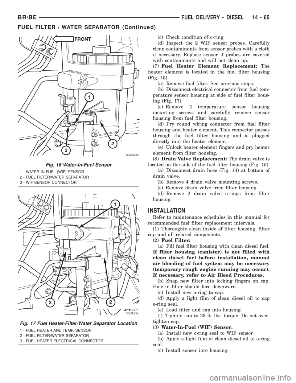
(7)Fuel Heater Element Replacement:The
heater element is located in the fuel filter housing
(Fig. 15).
(a) Remove fuel filter. See previous steps.
(b) Disconnect electrical connector from fuel tem-
perature sensor housing at side of fuel filter hous-
ing (Fig. 17).
(c) Remove 2 temperature sensor housing
mounting screws and carefully remove sensor
housing from fuel filter housing.
(d) Pry round wiring connector from fuel filter
housing and heater element. This connector passes
through the fuel filter housing and is plugged
directly into the heater element.
(e) Unlock heater element fingers and pry heater
element from filter housing.
(8)Drain Valve Replacement:The drain valve is
located on the side of the fuel filter housing (Fig. 15).
(a) Disconnect drain hose (Fig. 14) at bottom of
drain valve.
(b) Remove 4 drain valve mounting screws.
(c) Remove drain valve from filter housing.
(d) Remove 2 drain valve o-rings from filter
housing.
INSTALLATION
Refer to maintenance schedules in this manual for
recommended fuel filter replacement intervals.
(1) Thoroughly clean inside of filter housing, filter
cap and all related components.
(2)Fuel Filter:
(a) Fill fuel filter housing with clean diesel fuel.
If filter housing (canister) is not filled with
clean diesel fuel before installation, manual
air bleeding of fuel system may be necessary
(temporary rough engine running may occur).
If necessary, refer to Air Bleed Procedures.
(b) Snap new filter into locking fingers on cap.
Hole in filter should face downward.
(c) Install new o-ring to cap.
(d) Apply a light film of clean diesel oil to cap
o-ring seal.
(e) Load filter and cap into housing.
(f) Tighten cap to 25 ft. lbs. torque. Do not over-
tighten cap.
(3)Water-In-Fuel (WIF) Sensor:
(a) Install new o-ring seal to WIF sensor.
(b) Apply a light film of clean diesel oil to o-ring
seal.
(c) Install sensor into housing.
Fig. 16 Water-In-Fuel Sensor
1 - WATER-IN-FUEL (WIF) SENSOR
2 - FUEL FILTER/WATER SEPARATOR
3 - WIF SENSOR CONNECTOR
Fig. 17 Fuel Heater/Filter/Water Separator Location
1 - FUEL HEATER AND TEMP. SENSOR
2 - FUEL FILTER/WATER SEPARATOR
3 - FUEL HEATER ELECTRICAL CONNECTOR
BR/BEFUEL DELIVERY - DIESEL 14 - 65
FUEL FILTER / WATER SEPARATOR (Continued)
Page 1449 of 2255
LINKAGE - 2WD
TABLE OF CONTENTS
page page
LINKAGE - 2WD
DESCRIPTION.........................40
STANDARD PROCEDURE - LUBRICATION....40
REMOVAL.............................40
INSTALLATION.........................41SPECIFICATIONS
TORQUE CHART......................41
SPECIAL TOOLS
STEERING LINKAGE...................41
LINKAGE - 2WD
DESCRIPTION
Light duty (LD) and heavy duty (HD) steering link-
age is used with IFS suspensions. The linkage is
comprised of a idler arm, pitman arm, center link
and tie rod ends. Heavy duty linkage is used on 8800
and 10500 lb. GVW vehicles.
CAUTION: If any steering components are replaced
or serviced an alignment must be performed.
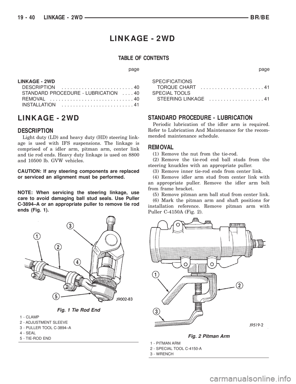
NOTE: When servicing the steering linkage, use
care to avoid damaging ball stud seals. Use Puller
C-3894±A or an appropriate puller to remove tie rod
ends (Fig. 1).
STANDARD PROCEDURE - LUBRICATION
Periodic lubrication of the idler arm is required.
Refer to Lubrication And Maintenance for the recom-
mended maintenance schedule.
REMOVAL
(1) Remove the nut from the tie-rod.
(2) Remove the tie-rod end ball studs from the
steering knuckles with an appropriate puller.
(3) Remove inner tie-rod ends from center link.
(4) Remove idler arm stud from center link with
an appropriate puller. Remove the idler arm bolt
from frame bracket.
(5) Remove pitman arm ball stud from center link.
(6) Mark the pitman arm and shaft positions for
installation reference. Remove pitman arm with
Puller C-4150A (Fig. 2).
Fig. 1 Tie Rod End
1 - CLAMP
2 - ADJUSTMENT SLEEVE
3 - PULLER TOOL C-3894±A
4 - SEAL
5 - TIE-ROD END
Fig. 2 Pitman Arm
1 - PITMAN ARM
2 - SPECIAL TOOL C-4150-A
3 - WRENCH
19 - 40 LINKAGE - 2WDBR/BE
Page 1451 of 2255
LINKAGE - 4WD
TABLE OF CONTENTS
page page
LINKAGE - 4WD
DESCRIPTION.........................42
STANDARD PROCEDURE - LUBRICATION....42
REMOVAL.............................42
INSTALLATION.........................43SPECIFICATIONS
TORQUE CHART......................43
SPECIAL TOOLS
STEERING LINKAGE...................44
LINKAGE - 4WD
DESCRIPTION
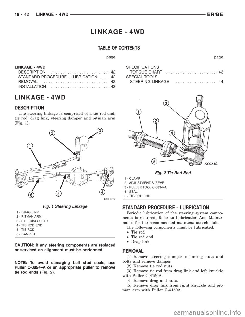
The steering linkage is comprised of a tie rod end,
tie rod, drag link, steering damper and pitman arm
(Fig. 1).
CAUTION: If any steering components are replaced
or serviced an alignment must be performed.
NOTE: To avoid damaging ball stud seals, use
Puller C-3894±A or an appropriate puller to remove
tie rod ends (Fig. 2).
STANDARD PROCEDURE - LUBRICATION
Periodic lubrication of the steering system compo-
nents is required. Refer to Lubrication And Mainte-
nance for the recommended maintenance schedule.
The following components must be lubricated:
²Tie rod
²Tie rod end
²Drag link
REMOVAL
(1) Remove steering damper mounting nuts and
bolts and remove damper.
(2) Remove tie rod nuts.
(3) Remove tie rod from drag link and left knuckle
with Puller C-4150A.
(4) Remove drag and nuts.
(5) Remove drag link from right knuckle and pit-
man arm with Puller C-4150A.
Fig. 1 Steering Linkage
1 - DRAG LINK
2 - PITMAN ARM
3 - STEERING GEAR
4 - TIE ROD END
5 - TIE ROD
6 - DAMPER
Fig. 2 Tie Rod End
1 - CLAMP
2 - ADJUSTMENT SLEEVE
3 - PULLER TOOL C-3894±A
4 - SEAL
5 - TIE-ROD END
19 - 42 LINKAGE - 4WDBR/BE