2002 DODGE RAM maintenance
[x] Cancel search: maintenancePage 1611 of 2255
In either case, air bubbles can cause overheating
and/or fluid oxidation, and varnishing. This can
interfere with normal valve, clutch, and accumulator
operation. Foaming can also result in fluid escaping
from the transmission vent where it may be mis-
taken for a leak.
Along with fluid level, it is important to check the
condition of the fluid. When the fluid smells burned,
and is contaminated with metal or friction material
particles, a complete transmission recondition is
needed. Be sure to examine the fluid on the dipstick
closely. If there is any doubt about its condition,
drain out a sample for a double check.
After the fluid has been checked, seat the dipstick
fully to seal out water and dirt.
The transmission has a dipstick to check oil level.
It is located on the right side of the engine. Be sure
to wipe all dirt from dipstick handle before removing.
Fluid level is checked with the engine running at
curb idle speed, the transmission in NEUTRAL and
the transmission fluid at normal operating tempera-
ture.The engine should be running at idle
speed for at least one minute, with the vehicle
on level ground.
The transmission fluid level can be checked two
ways.
PROCEDURE ONE
(1) Transmission fluid must be at normal operat-
ing temperature for accurate fluid level check. Drive
vehicle if necessary to bring fluid temperature up to
normal hot operating temperature of 82ÉC (180ÉF).
(2) Position vehicle on level surface.
(3) Start and run engine at curb idle speed.
(4) Apply parking brakes.
(5) Shift transmission momentarily into all gear
ranges. Then shift transmission back to NEUTRAL.
(6) Clean top of filler tube and dipstick to keep
dirt from entering tube.
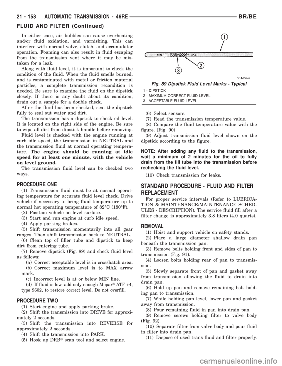
(7) Remove dipstick (Fig. 89) and check fluid level
as follows:
(a) Correct acceptable level is in crosshatch area.
(b) Correct maximum level is to MAX arrow
mark.
(c) Incorrect level is at or below MIN line.
(d)
If fluid is low, add only enough MopartATF +4,
type 9602, to restore correct level. Do not overfill.
PROCEDURE TWO
(1) Start engine and apply parking brake.
(2) Shift the transmission into DRIVE for approxi-
mately 2 seconds.
(3) Shift the transmission into REVERSE for
approximately 2 seconds.
(4) Shift the transmission into PARK.
(5) Hook up DRBtscan tool and select engine.(6) Select sensors.
(7) Read the transmission temperature value.
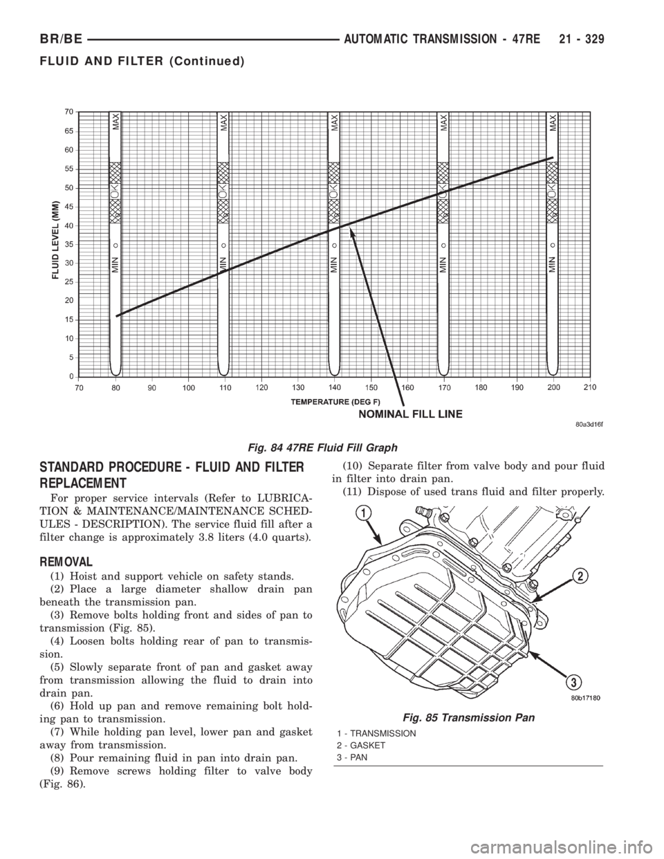
(8) Compare the fluid temperature value with the
figure. (Fig. 90)
(9) Adjust transmission fluid level shown on the
dipstick according to the figure.
NOTE: After adding any fluid to the transmission,
wait a minimum of 2 minutes for the oil to fully
drain from the fill tube into the transmission before
rechecking the fluid level.
(10) Check transmission for leaks.
STANDARD PROCEDURE - FLUID AND FILTER
REPLACEMENT
For proper service intervals (Refer to LUBRICA-
TION & MAINTENANCE/MAINTENANCE SCHED-
ULES - DESCRIPTION). The service fluid fill after a
filter change is approximately 3.8 liters (4.0 quarts).
REMOVAL
(1) Hoist and support vehicle on safety stands.
(2) Place a large diameter shallow drain pan
beneath the transmission pan.
(3) Remove bolts holding front and sides of pan to
transmission (Fig. 91).
(4) Loosen bolts holding rear of pan to transmis-
sion.
(5) Slowly separate front of pan and gasket away
from transmission allowing the fluid to drain into
drain pan.
(6) Hold up pan and remove remaining bolt hold-
ing pan to transmission.
(7) While holding pan level, lower pan and gasket
away from transmission.
(8) Pour remaining fluid in pan into drain pan.
(9) Remove screws holding filter to valve body
(Fig. 92).
(10) Separate filter from valve body and pour fluid
in filter into drain pan.
(11) Dispose of used trans fluid and filter properly.
Fig. 89 Dipstick Fluid Level Marks - Typical
1 - DIPSTICK
2 - MAXIMUM CORRECT FLUID LEVEL
3 - ACCEPTABLE FLUID LEVEL
21 - 158 AUTOMATIC TRANSMISSION - 46REBR/BE
FLUID AND FILTER (Continued)
Page 1782 of 2255
STANDARD PROCEDURE - FLUID AND FILTER
REPLACEMENT
For proper service intervals (Refer to LUBRICA-
TION & MAINTENANCE/MAINTENANCE SCHED-
ULES - DESCRIPTION). The service fluid fill after a
filter change is approximately 3.8 liters (4.0 quarts).
REMOVAL
(1) Hoist and support vehicle on safety stands.
(2) Place a large diameter shallow drain pan
beneath the transmission pan.
(3) Remove bolts holding front and sides of pan to
transmission (Fig. 85).
(4) Loosen bolts holding rear of pan to transmis-
sion.
(5) Slowly separate front of pan and gasket away
from transmission allowing the fluid to drain into
drain pan.
(6) Hold up pan and remove remaining bolt hold-
ing pan to transmission.
(7) While holding pan level, lower pan and gasket
away from transmission.
(8) Pour remaining fluid in pan into drain pan.
(9) Remove screws holding filter to valve body
(Fig. 86).(10) Separate filter from valve body and pour fluid
in filter into drain pan.
(11) Dispose of used trans fluid and filter properly.
Fig. 84 47RE Fluid Fill Graph
Fig. 85 Transmission Pan
1 - TRANSMISSION
2 - GASKET
3-PAN
BR/BEAUTOMATIC TRANSMISSION - 47RE 21 - 329
FLUID AND FILTER (Continued)
Page 1957 of 2255
METHOD 1 (RELOCATE WHEEL ON HUB)
(1) Drive vehicle a short distance to eliminate tire
flat spotting from a parked position.
(2) Check wheel bearings and adjust if adjustable
or replace if necessary.
(3) Check the wheel mounting surface.
(4) Relocate wheel on the mounting, two studs
over from the original position.
(5) Tighten wheel nuts until all are properly
torqued, to eliminate brake distortion.
(6) Check radial runout. If still excessive, mark
tire sidewall, wheel, and stud at point of maximum
runout and proceed to Method 2.
METHOD 2 (RELOCATE TIRE ON WHEEL)
NOTE: Rotating the tire on wheel is particularly
effective when there is runout in both tire and
wheel.
(1) Remove tire from wheel and mount wheel on
service dynamic balance machine.
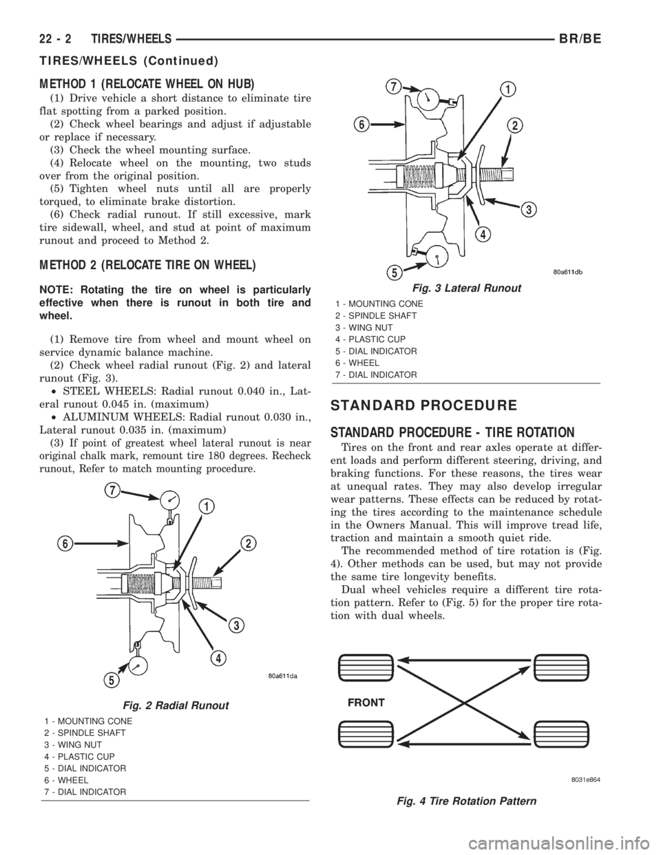
(2) Check wheel radial runout (Fig. 2) and lateral
runout (Fig. 3).
²STEEL WHEELS: Radial runout 0.040 in., Lat-
eral runout 0.045 in. (maximum)
²ALUMINUM WHEELS: Radial runout 0.030 in.,
Lateral runout 0.035 in. (maximum)
(3)
If point of greatest wheel lateral runout is near
original chalk mark, remount tire 180 degrees. Recheck
runout, Refer to match mounting procedure.
STANDARD PROCEDURE
STANDARD PROCEDURE - TIRE ROTATION
Tires on the front and rear axles operate at differ-
ent loads and perform different steering, driving, and
braking functions. For these reasons, the tires wear
at unequal rates. They may also develop irregular
wear patterns. These effects can be reduced by rotat-
ing the tires according to the maintenance schedule
in the Owners Manual. This will improve tread life,
traction and maintain a smooth quiet ride.
The recommended method of tire rotation is (Fig.
4). Other methods can be used, but may not provide
the same tire longevity benefits.
Dual wheel vehicles require a different tire rota-
tion pattern. Refer to (Fig. 5) for the proper tire rota-
tion with dual wheels.
Fig. 2 Radial Runout
1 - MOUNTING CONE
2 - SPINDLE SHAFT
3 - WING NUT
4 - PLASTIC CUP
5 - DIAL INDICATOR
6 - WHEEL
7 - DIAL INDICATOR
Fig. 3 Lateral Runout
1 - MOUNTING CONE
2 - SPINDLE SHAFT
3 - WING NUT
4 - PLASTIC CUP
5 - DIAL INDICATOR
6 - WHEEL
7 - DIAL INDICATOR
Fig. 4 Tire Rotation Pattern
22 - 2 TIRES/WHEELSBR/BE
TIRES/WHEELS (Continued)
Page 1966 of 2255
DIAGNOSIS AND TESTING
WHEEL INSPECTION
Inspect wheels for:
²Excessive run out
²Dents or cracks
²Damaged wheel lug nut holes
²Air Leaks from any area or surface of the rim
NOTE: Do not attempt to repair a wheel by hammer-
ing, heating or welding.
If a wheel is damaged an original equipment
replacement wheel should be used. When obtaining
replacement wheels, they should be equivalent in
load carrying capacity. The diameter, width, offset,
pilot hole and bolt circle of the wheel should be the
same as the original wheel.
WARNING: FAILURE TO USE EQUIVALENT REPLACE-
MENT WHEELS MAY ADVERSELY AFFECT THE
SAFETY AND HANDLING OF THE VEHICLE. USED
WHEELS ARE NOT RECOMMENDED. THE SERVICE
HISTORY OF THE WHEEL MAY HAVE INCLUDED
SEVERE TREATMENT OR VERY HIGH MILEAGE. THE
RIM COULD FAIL WITHOUT WARNING.
STANDARD PROCEDURE - DUAL REAR WHEEL
INSTALLATION
Dual rear wheels use a special heavy duty lug nut
wrench. It is recommended to remove and install dual
rear wheels only when the proper wrench is available.
The wrench is also use to remove wheel center caps for
more information refer to Owner's Manual.
The tires on both wheels must be completely raised
off the ground when tightening the lug nuts. This
will ensure correct wheel centering and maximum
wheel clamping.
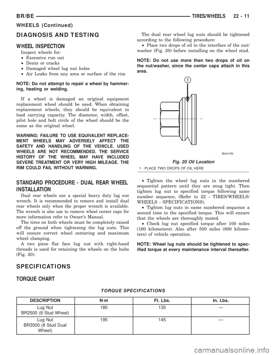
A two piece flat face lug nut with right-hand
threads is used for retaining the wheels on the hubs
(Fig. 20).The dual rear wheel lug nuts should be tightened
according to the following procedure:
²Place two drops of oil to the interface of the nut/
washer (Fig. 20) before installing on the wheel stud.
NOTE: Do not use more then two drops of oil on
the nut/washer, since the center caps attach in this
area.
²Tighten the wheel lug nuts in the numbered
sequential pattern until they are snug tight. Then
tighten lug nut to specified torque following same
number sequence, (Refer to 22 - TIRES/WHEELS/
WHEELS - SPECIFICATIONS).
²Tighten lug nuts in same numbered sequence a
second time to the specified torque. This will ensure
that the wheels are thoroughly mated.
²Check lug nut specified torque after 100 miles
(160 kilometers). Also after 500 miles (800 kilome-
ters) of vehicle operation.
NOTE: Wheel lug nuts should be tightened to spec-
ified torque at every maintenance interval thereafter.
SPECIFICATIONS
TORQUE CHART
TORQUE SPECIFICATIONS
DESCRIPTION N´m Ft. Lbs. In. Lbs.
Lug Nut
BR2500 (8 Stud Wheel)180 135 Ð
Lug Nut
BR3500 (8 Stud Dual
Wheel)195 145 Ð
Fig. 20 Oil Location
1 - PLACE TWO DROPS OF OIL HERE
BR/BETIRES/WHEELS 22 - 11
WHEELS (Continued)
Page 1969 of 2255
DIAGNOSIS AND TESTING
DIAGNOSIS AND TESTING - WATER LEAKS
Water leaks can be caused by poor sealing,
improper body component alignment, body seam
porosity, missing plugs, or blocked drain holes. Cen-
trifugal and gravitational force can cause water to
drip from a location away from the actual leak point,
making leak detection difficult. All body sealing
points should be water tight in normal wet-driving
conditions. Water flowing downward from the front of
the vehicle should not enter the passenger or luggage
compartment. Moving sealing surfaces will not
always seal water tight under all conditions. At
times, side glass or door seals will allow water to
enter the passenger compartment during high pres-
sure washing or hard driving rain (severe) condi-
tions. Overcompensating on door or glass
adjustments to stop a water leak that occurs under
severe conditions can cause premature seal wear and
excessive closing or latching effort. After completing
a repair, water test vehicle to verify leak has stopped
before returning vehicle to use.
VISUAL INSPECTION BEFORE WATER LEAK TESTS
Verify that floor and body plugs are in place, body
drains are clear, and body components are properly
aligned and sealed. If component alignment or seal-
ing is necessary, refer to the appropriate section of
this group for proper procedures.
WATER LEAK TESTS
WARNING: DO NOT USE ELECTRIC SHOP LIGHTS
OR TOOLS IN WATER TEST AREA. PERSONAL
INJURY CAN RESULT.
When the conditions causing a water leak have
been determined, simulate the conditions as closely
as possible.
²If a leak occurs with the vehicle parked in a
steady light rain, flood the leak area with an open-
ended garden hose.²If a leak occurs while driving at highway speeds
in a steady rain, test the leak area with a reasonable
velocity stream or fan spray of water. Direct the
spray in a direction comparable to actual conditions.
²If a leak occurs when the vehicle is parked on an
incline, hoist the end or side of the vehicle to simu-
late this condition. This method can be used when
the leak occurs when the vehicle accelerates, stops or
turns. If the leak occurs on acceleration, hoist the
front of the vehicle. If the leak occurs when braking,
hoist the back of the vehicle. If the leak occurs on left
turns, hoist the left side of the vehicle. If the leak
occurs on right turns, hoist the right side of the vehi-
cle. For hoisting recommendations refer to Group 0,
Lubrication and Maintenance, General Information
section.
WATER LEAK DETECTION
To detect a water leak point-of-entry, do a water
test and watch for water tracks or droplets forming
on the inside of the vehicle. If necessary, remove inte-
rior trim covers or panels to gain visual access to the
leak area. If the hose cannot be positioned without
being held, have someone help do the water test.
Some water leaks must be tested for a considerable
length of time to become apparent. When a leak
appears, find the highest point of the water track or
drop. The highest point usually will show the point of
entry. After leak point has been found, repair the
leak and water test to verify that the leak has
stopped.
Locating the entry point of water that is leaking
into a cavity between panels can be difficult. The
trapped water may splash or run from the cavity,
often at a distance from the entry point. Most water
leaks of this type become apparent after accelerating,
stopping, turning, or when on an incline.
MIRROR INSPECTION METHOD
When a leak point area is visually obstructed, use
a suitable mirror to gain visual access. A mirror can
also be used to deflect light to a limited-access area
to assist in locating a leak point.
23 - 2 BODYBR/BE
BODY (Continued)
Page 2059 of 2255
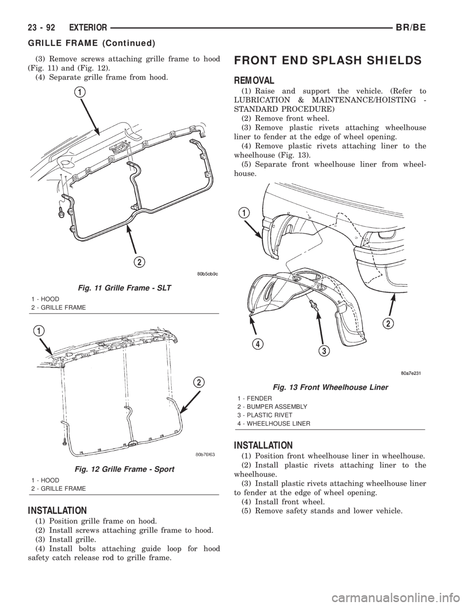
(3) Remove screws attaching grille frame to hood
(Fig. 11) and (Fig. 12).
(4) Separate grille frame from hood.
INSTALLATION
(1) Position grille frame on hood.
(2) Install screws attaching grille frame to hood.
(3) Install grille.
(4) Install bolts attaching guide loop for hood
safety catch release rod to grille frame.
FRONT END SPLASH SHIELDS
REMOVAL
(1) Raise and support the vehicle. (Refer to
LUBRICATION & MAINTENANCE/HOISTING -
STANDARD PROCEDURE)
(2) Remove front wheel.
(3) Remove plastic rivets attaching wheelhouse
liner to fender at the edge of wheel opening.
(4) Remove plastic rivets attaching liner to the
wheelhouse (Fig. 13).
(5) Separate front wheelhouse liner from wheel-
house.
INSTALLATION
(1) Position front wheelhouse liner in wheelhouse.
(2) Install plastic rivets attaching liner to the
wheelhouse.
(3) Install plastic rivets attaching wheelhouse liner
to fender at the edge of wheel opening.
(4) Install front wheel.
(5) Remove safety stands and lower vehicle.
Fig. 11 Grille Frame - SLT
1 - HOOD
2 - GRILLE FRAME
Fig. 12 Grille Frame - Sport
1 - HOOD
2 - GRILLE FRAME
Fig. 13 Front Wheelhouse Liner
1 - FENDER
2 - BUMPER ASSEMBLY
3 - PLASTIC RIVET
4 - WHEELHOUSE LINER
23 - 92 EXTERIORBR/BE
GRILLE FRAME (Continued)
Page 2216 of 2255
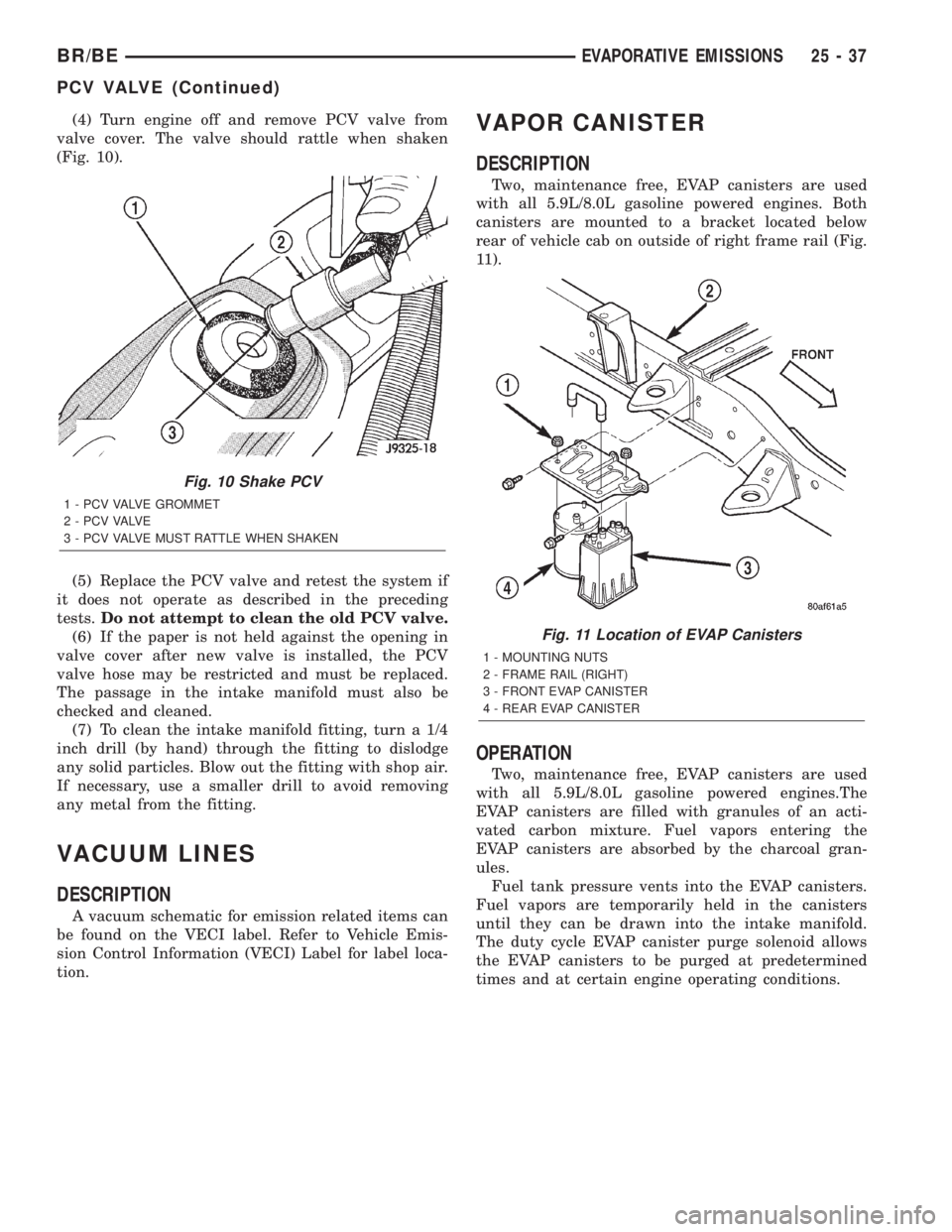
(4) Turn engine off and remove PCV valve from
valve cover. The valve should rattle when shaken
(Fig. 10).
(5) Replace the PCV valve and retest the system if
it does not operate as described in the preceding
tests.Do not attempt to clean the old PCV valve.
(6) If the paper is not held against the opening in
valve cover after new valve is installed, the PCV
valve hose may be restricted and must be replaced.
The passage in the intake manifold must also be
checked and cleaned.
(7) To clean the intake manifold fitting, turn a 1/4
inch drill (by hand) through the fitting to dislodge
any solid particles. Blow out the fitting with shop air.
If necessary, use a smaller drill to avoid removing
any metal from the fitting.
VACUUM LINES
DESCRIPTION
A vacuum schematic for emission related items can
be found on the VECI label. Refer to Vehicle Emis-
sion Control Information (VECI) Label for label loca-
tion.
VAPOR CANISTER
DESCRIPTION
Two, maintenance free, EVAP canisters are used
with all 5.9L/8.0L gasoline powered engines. Both
canisters are mounted to a bracket located below
rear of vehicle cab on outside of right frame rail (Fig.
11).
OPERATION
Two, maintenance free, EVAP canisters are used
with all 5.9L/8.0L gasoline powered engines.The
EVAP canisters are filled with granules of an acti-
vated carbon mixture. Fuel vapors entering the
EVAP canisters are absorbed by the charcoal gran-
ules.
Fuel tank pressure vents into the EVAP canisters.
Fuel vapors are temporarily held in the canisters
until they can be drawn into the intake manifold.
The duty cycle EVAP canister purge solenoid allows
the EVAP canisters to be purged at predetermined
times and at certain engine operating conditions.
Fig. 10 Shake PCV
1 - PCV VALVE GROMMET
2 - P C V VA LV E
3 - PCV VALVE MUST RATTLE WHEN SHAKEN
Fig. 11 Location of EVAP Canisters
1 - MOUNTING NUTS
2 - FRAME RAIL (RIGHT)
3 - FRONT EVAP CANISTER
4 - REAR EVAP CANISTER
BR/BEEVAPORATIVE EMISSIONS 25 - 37
PCV VALVE (Continued)
Page 2236 of 2255
LINE COUPLERS - OPERATION, A/C......24-41
LINE COUPLERS - STANDARD
PROCEDURE, A/C....................24-44
LINE LEAKS - DIAGNOSIS AND TESTING,
HIGH-PRESSURE FUEL................14-78
LINER - INSTALLATION, REAR
WHEELHOUSE.......................23-96
LINER - REMOVAL, REAR WHEELHOUSE . . 23-96
LINES - CLEANING AND INSPECTION,
OIL COOLER........................9-179
LINES - DESCRIPTION, FUEL............14-8
LINES - DESCRIPTION, HIGH PRESSURE
FUEL..............................14-78
LINES - DESCRIPTION, REFRIGERANT....24-40
LINES - DESCRIPTION, VACUUM........25-37
LINES - OPERATION, HIGH PRESSURE
FUEL..............................14-78
LINES - OPERATION, REFRIGERANT......24-41
LINK CONNECTOR - DESCRIPTION, DATA . 8E-12
LINK CONNECTOR - OPERATION, DATA . . . 8E-12
LINKAGE - 2WD - DESCRIPTION........19-40
LINKAGE - 2WD - INSTALLATION........19-41
LINKAGE - 2WD - REMOVAL............19-40
LINKAGE - 4WD - DESCRIPTION........19-42
LINKAGE - 4WD - INSTALLATION........19-43
LINKAGE - 4WD - REMOVAL............19-42
LINKAGE - INSTALLATION...............6-16
LINKAGE - REMOVAL..................6-15
LINKAGE, SPECIAL TOOLS - STEERING . . . 19-41,
19-44
LINK/COIL SUSPENSION - STANDARD
PROCEDURE, ALIGNMENT...............2-5
LINK/COIL SUSPENSION, SPECIAL
TOOLS..............................2-16
LIQUID LINE - INSTALLATION...........24-52
LIQUID LINE - REMOVAL..............24-52
LOAD TEST - STANDARD PROCEDURE....8F-12
LOADS - STANDARD PROCEDURE,
TESTING FOR A SHORT TO GROUND
ON FUSES POWERING SEVERAL......8W-01-9
LOCATION - DESCRIPTION, CONNECTOR/
GROUND/SPLICE...................8W-91-1
LOCATIONS, SPECIFICATIONS - BODY
SEALER............................23-47
LOCATIONS, SPECIFICATIONS -
STRUCTURAL ADHESIVE...............23-44
LOCATIONS, SPECIFICATIONS - WELD.....23-4
LOCK & REMOTE KEYLESS ENTRY
SYSTEM - DIAGNOSIS AND TESTING,
POWER.............................8N-5
LOCK - STANDARD PROCEDURE,
HYDROSTATIC...............9-11,9-122,9-66
LOCK CYLINDER - DIAGNOSIS AND
TESTING, IGNITION SWITCH AND KEY.....19-9
LOCK CYLINDER - INSTALLATION.......23-74
LOCK CYLINDER - INSTALLATION.......19-10
LOCK CYLINDER - REMOVAL...........23-74
LOCK CYLINDER - REMOVAL...........19-10
LOCK MOTOR - DESCRIPTION, POWER....8N-7
LOCK MOTOR - DIAGNOSIS AND
TESTING, POWER.....................8N-7
LOCK MOTOR - OPERATION, POWER.....8N-7
LOCK SWITCH - DESCRIPTION, DOOR
CYLINDER...........................8N-5
LOCK SWITCH - DESCRIPTION, POWER . . . 8N-8
LOCK SWITCH - DIAGNOSIS AND
TESTING, DOOR CYLINDER.............8N-6
LOCK SWITCH - DIAGNOSIS AND
TESTING, POWER.....................8N-9
LOCK SWITCH - INSTALLATION, DOOR
CYLINDER...........................8N-6
LOCK SWITCH - OPERATION, DOOR
CYLINDER...........................8N-5
LOCK SWITCH - OPERATION, POWER.....8N-8
LOCK SWITCH - REMOVAL, DOOR
CYLINDER...........................8N-6
LOCKS - DESCRIPTION, POWER.........8N-1
LOCKS - DIAGNOSIS AND TESTING,
POWER.............................8N-4
LOCKS - OPERATION, POWER
...........8N-3
LOOP ADJUSTER - INSTALLATION, SEAT
BELT TURNING
......................8O-29
LOOP ADJUSTER - REMOVAL, SEAT
BELT TURNING
......................8O-29
LOOP HGT ADJUSTER KNOB -
INSTALLATION, TURNING
..............8O-30
LOOP HGT ADJUSTER KNOB -
REMOVAL, TURNING
.................8O-30LOW FUEL INDICATOR - DESCRIPTION . . . 8J-22
LOW FUEL INDICATOR - OPERATION.....8J-22
LOW MOUNTED - INSTALLATION, SIDE
VIEW MIRROR.......................23-98
LOW MOUNTED - REMOVAL, SIDE VIEW
MIRROR...........................23-98
LOW PRESSURE SWITCH -
DESCRIPTION, A/C...................24-21
LOW PRESSURE SWITCH - DIAGNOSIS
AND TESTING, A/C...................24-21
LOW PRESSURE SWITCH -
INSTALLATION, A/C...................24-21
LOW PRESSURE SWITCH - OPERATION,
A/C................................24-21
LOW PRESSURE SWITCH - REMOVAL,
A/C................................24-21
LOWER - INSTALLATION, LATCH........23-80
LOWER - INSTALLATION, LATCH
STRIKER...........................23-82
LOWER - REMOVAL, LATCH............23-80
LOWER - REMOVAL, LATCH STRIKER....23-82
LOWER BALL JOINT - DIAGNOSIS AND
TESTING............................2-10
LOWER CONTROL ARM - INSTALLATION . . 2-10,
2-20
LOWER CONTROL ARM - REMOVAL . . 2-10,2-20
LOWER FASCIA - INSTALLATION, FRONT . . . 13-3
LOWER FASCIA - REMOVAL, FRONT......13-3
LUBRICANTS - STANDARD PROCEDURE,
CLASSIFICATION OF....................0-1
LUBRICATION - DESCRIPTION....9-174,9-42,9-98
LUBRICATION - DESCRIPTION, AXLE.......0-5
LUBRICATION - DIAGNOSIS AND
TESTING, ENGINE DIAGNOSIS........9-63,9-8
LUBRICATION - OPERATION....9-174,9-42,9-98
LUBRICATION - STANDARD PROCEDURE . 19-40,
19-42
LUMBAR CONTROL SWITCH -
DESCRIPTION.......................8N-18
LUMBAR CONTROL SWITCH -
OPERATION.........................8N-19
LUMBAR CONTROL SWITCH - REMOVAL . 8N-19
LUMBAR MOTOR - DESCRIPTION.......8N-19
LUMBAR MOTOR - DIAGNOSIS AND
TESTING...........................8N-19
LUMBAR MOTOR - OPERATION.........8N-19
LUMBAR SUPPORT - INSTALLATION....23-133
LUMBAR SUPPORT - REMOVAL........23-132
MAIN BEARING CLEARANCE -
STANDARD PROCEDURE...............9-159
MAIN BEARING FITTING - STANDARD
PROCEDURE, CRANKSHAFT.............9-31
MAIN BEARINGS - DESCRIPTION,
CRANKSHAFT........................9-31
MAIN BEARINGS - INSTALLATION,
CRANKSHAFT....................9-32,9-88
MAIN BEARINGS - OPERATION,
CRANKSHAFT........................9-31
MAIN BEARINGS - REMOVAL,
CRANKSHAFT....................9-31,9-88
MAIN BEARINGS - STANDARD
PROCEDURE, FITTING CRANKSHAFT......9-88
MAINTENANCE SCHEDULES -
DESCRIPTION.........................0-7
MALFUNCTION INDICATOR LAMP MIL -
DESCRIPTION.......................8J-23
MALFUNCTION INDICATOR LAMP MIL -
OPERATION.........................8J-23
MANAGER - DESCRIPTION, TASK........25-17
MANAGER - OPERATION, TASK.........25-21
MANIFOLD - CLEANING, EXHAUST . 9-109,9-185,
9-53
MANIFOLD - CLEANING, INTAKE . . . 9-107,9-184,
9-51
MANIFOLD - DESCRIPTION, EXHAUST . . . 9-109,
9-53
MANIFOLD - DESCRIPTION, FUEL DRAIN . . 14-89
MANIFOLD - DESCRIPTION, INTAKE . . 9-106,9-50
MANIFOLD - INSPECTION, EXHAUST
.....9-109,
9-186,9-53
MANIFOLD - INSPECTION, INTAKE
. 9-108,9-184,
9-51
MANIFOLD - INSTALLATION, EXHAUST
. . . 9-109,
9-186,9-53
MANIFOLD - INSTALLATION, FUEL
DRAIN
.............................14-90
MANIFOLD - INSTALLATION, INTAKE
.....9-108,
9-184,9-51MANIFOLD - OPERATION, EXHAUST . . 9-109,9-53
MANIFOLD - OPERATION, FUEL DRAIN . . . 14-89
MANIFOLD - OPERATION, INTAKE........9-50
MANIFOLD - REMOVAL, EXHAUST . . 9-109,9-185,
9-53
MANIFOLD - REMOVAL, FUEL DRAIN.....14-90
MANIFOLD - REMOVAL, INTAKE . . . 9-107,9-184,
9-50
MANIFOLD LEAKAGE - DIAGNOSIS AND
TESTING, INTAKE................9-106,9-50
MANUAL - NV4500 - ASSEMBLY........21-21
MANUAL - NV4500 - CLEANING.........21-20
MANUAL - NV4500 - DESCRIPTION.......21-1
MANUAL - NV4500 - DIAGNOSIS AND
TESTING............................21-3
MANUAL - NV4500 - DISASSEMBLY.......21-5
MANUAL - NV4500 - INSPECTION.......21-20
MANUAL - NV4500 - INSTALLATION......21-37
MANUAL - NV4500 - OPERATION.........21-3
MANUAL - NV4500 - REMOVAL..........21-4
MANUAL - NV4500 - SPECIFICATIONS....21-38
MANUAL - NV5600 - ASSEMBLY........21-64
MANUAL - NV5600 - CLEANING.........21-63
MANUAL - NV5600 - DESCRIPTION......21-46
MANUAL - NV5600 - DIAGNOSIS AND
TESTING...........................21-48
MANUAL - NV5600 - DISASSEMBLY......21-49
MANUAL - NV5600 - INSPECTION.........21-63
MANUAL - NV5600 - INSTALLATION......21-78
MANUAL - NV5600 - OPERATION........21-48
MANUAL - NV5600 - REMOVAL.........21-49
MANUAL - NV5600 - SPECIFICATIONS....21-79
MANUAL BLEEDING - STANDARD
PROCEDURE..........................5-7
MANUAL TRANSMISSION -
DESCRIPTION.........................0-5
MANUAL TRANSMISSION -
INSTALLATION, SHIFT BOOT...........23-122
MANUAL TRANSMISSION - REMOVAL,
SHIFT BOOT........................23-122
MAP SENSOR - INSTALLATION.........14-108
MARKER LAMP - INSTALLATION........8L-23
MARKER LAMP - REMOVAL............8L-23
MASTER CYLINDER - DESCRIPTION......5-26
MASTER CYLINDER - INSTALLATION......5-28
MASTER CYLINDER - OPERATION........5-26
MASTER CYLINDER - REMOVAL..........5-27
MASTER CYLINDER BLEEDING -
STANDARD PROCEDURE................5-27
MASTER CYLINDER/POWER BOOSTER -
DIAGNOSIS AND TESTING..............5-26
MATCH MOUNTING - STANDARD
PROCEDURE.........................22-3
MATS - INSTALLATION, CARPETS AND
FLOOR............................23-123
MATS - REMOVAL, CARPETS AND
FLOOR............................23-123
MEASUREMENT - STANDARD
PROCEDURE, CASTER CORRECTION.......2-3
MEASUREMENTS, SPECIFICATIONS -
BODY GAP AND FLUSH................23-56
MEASURING TIMING CHAIN STRETCH -
INSPECTION....................9-111,9-54
MECHANICAL - DIAGNOSIS AND
TESTING, ENGINE DIAGNOSIS . . . 9-116,9-6,9-61
MECHANISM - DESCRIPTION, SHIFT....21-208,
21-379
MECHANISM - NV4500 - INSTALLATION,
SHIFT..............................21-44
MECHANISM - NV4500 - REMOVAL,
SHIFT..............................21-43
MECHANISM - OPERATION, SHIFT......21-208,
21-379
METRIC SYSTEM - DESCRIPTION......Intro.-9
MICRO-RELAY - DESCRIPTION.......8W-97-13
MICRO-RELAY - DIAGNOSIS AND
TESTING........................8W-97-14
MICRO-RELAY - INSTALLATION......8W-97-14
MICRO-RELAY - OPERATION........8W-97-14
MICRO-RELAY - REMOVAL
..........8W-97-14
MIDTRONICS ELECTRICAL TESTER -
STANDARD PROCEDURE, USING
........8F-15
MIL - DESCRIPTION, MALFUNCTION
INDICATOR LAMP
....................8J-23
MIL - OPERATION, MALFUNCTION
INDICATOR LAMP
....................8J-23
MILE, SPECIFICATIONS - TIRE
REVOLUTIONS PER
....................22-9
BR/BEINDEX 19
Description Group-Page Description Group-Page Description Group-Page