2002 DODGE RAM tires
[x] Cancel search: tiresPage 196 of 2255

mile or two. However, if the lining is both soaked and
dirt contaminated, cleaning and/or replacement will
be necessary.
BRAKE LINING CONTAMINATION
Brake lining contamination is mostly a product of
leaking calipers or wheel cylinders, worn seals, driv-
ing through deep water puddles, or lining that has
become covered with grease and grit during repair.
Contaminated lining should be replaced to avoid fur-
ther brake problems.
WHEEL AND TIRE PROBLEMS
Some conditions attributed to brake components
may actually be caused by a wheel or tire problem.
A damaged wheel can cause shudder, vibration and
pull. A worn or damaged tire can also cause pull.
Severely worn tires with very little tread left can
produce a grab-like condition as the tire loses and
recovers traction. Flat-spotted tires can cause vibra-
tion and generate shudder during brake operation. A
tire with internal damage such as a severe bruise,
cut, or ply separation can cause pull and vibration.
BRAKE NOISES
Some brake noise is common with rear drum
brakes and on some disc brakes during the first few
stops after a vehicle has been parked overnight or
stored. This is primarily due to the formation of trace
corrosion (light rust) on metal surfaces. This light
corrosion is typically cleared from the metal surfaces
after a few brake applications causing the noise to
subside.
BRAKE SQUEAK/SQUEAL
Brake squeak or squeal may be due to linings that
are wet or contaminated with brake fluid, grease, or
oil. Glazed linings and rotors with hard spots can
also contribute to squeak. Dirt and foreign material
embedded in the brake lining will also cause squeak/
squeal.
A very loud squeak or squeal is frequently a sign of
severely worn brake lining. If the lining has worn
through to the brake shoes in spots, metal-to-metal
contact occurs. If the condition is allowed to continue,
rotors and drums can become so scored that replace-
ment is necessary.
BRAKE CHATTER
Brake chatter is usually caused by loose or worn
components, or glazed/burnt lining. Rotors with hard
spots can also contribute to chatter. Additional causes
of chatter are out-of-tolerance rotors, brake lining not
securely attached to the shoes, loose wheel bearings
and contaminated brake lining.THUMP/CLUNK NOISE
Thumping or clunk noises during braking are fre-
quentlynotcaused by brake components. In many
cases, such noises are caused by loose or damaged
steering, suspension, or engine components. However,
calipers that bind on the slide surfaces can generate
a thump or clunk noise. In addition, worn out,
improperly adjusted, or improperly assembled rear
brake shoes can also produce a thump noise.
STANDARD PROCEDURE
STANDARD PROCEDURE - MANUAL BLEEDING
Use Mopar brake fluid, or an equivalent quality
fluid meeting SAE J1703-F and DOT 3 standards
only. Use fresh, clean fluid from a sealed container at
all times.
(1) Remove reservoir filler caps and fill reservoir.
(2) If calipers, or wheel cylinders were overhauled,
open all caliper and wheel cylinder bleed screws.
Then close each bleed screw as fluid starts to drip
from it. Top off master cylinder reservoir once more
before proceeding.
(3) Attach one end of bleed hose to bleed screw
and insert opposite end in glass container partially
filled with brake fluid (Fig. 1). Be sure end of bleed
hose is immersed in fluid.
(4)
Open up bleeder, then have a helper press down
the brake pedal. Once the pedal is down close the
bleeder. Repeat bleeding until fluid stream is clear and
free of bubbles. Then move to the next wheel.
Fig. 1 Bleed Hose Setup
1 - BLEED HOSE
2 - FLUID CONTAINER PARTIALLY FILLED WITH FLUID
BR/BEBRAKES - BASE 5 - 7
HYDRAULIC/MECHANICAL (Continued)
Page 203 of 2255
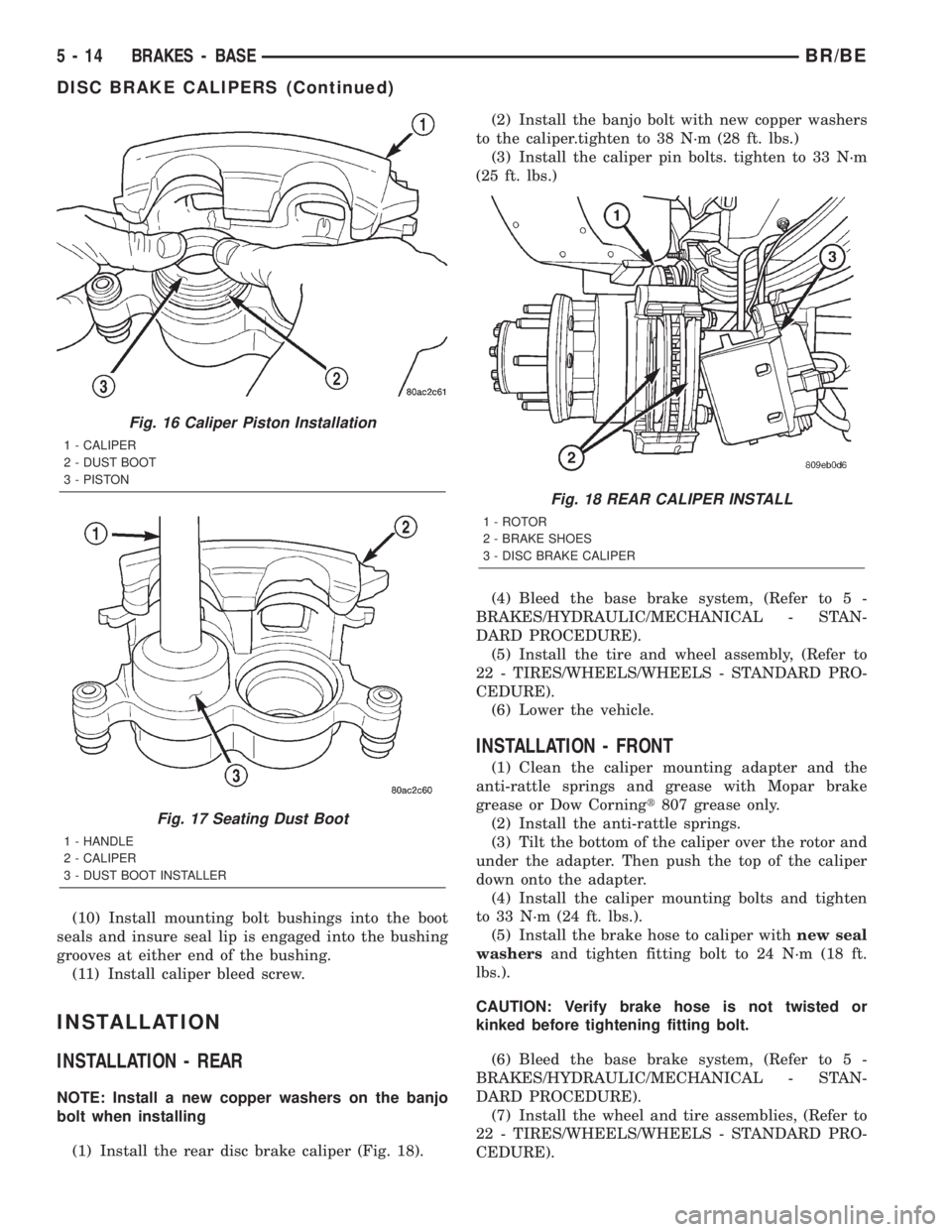
(10) Install mounting bolt bushings into the boot
seals and insure seal lip is engaged into the bushing
grooves at either end of the bushing.
(11) Install caliper bleed screw.
INSTALLATION
INSTALLATION - REAR
NOTE: Install a new copper washers on the banjo
bolt when installing
(1) Install the rear disc brake caliper (Fig. 18).(2) Install the banjo bolt with new copper washers
to the caliper.tighten to 38 N´m (28 ft. lbs.)
(3) Install the caliper pin bolts. tighten to 33 N´m
(25 ft. lbs.)
(4) Bleed the base brake system, (Refer to 5 -
BRAKES/HYDRAULIC/MECHANICAL - STAN-
DARD PROCEDURE).
(5) Install the tire and wheel assembly, (Refer to
22 - TIRES/WHEELS/WHEELS - STANDARD PRO-
CEDURE).
(6) Lower the vehicle.
INSTALLATION - FRONT
(1) Clean the caliper mounting adapter and the
anti-rattle springs and grease with Mopar brake
grease or Dow Corningt807 grease only.
(2) Install the anti-rattle springs.
(3) Tilt the bottom of the caliper over the rotor and
under the adapter. Then push the top of the caliper
down onto the adapter.
(4) Install the caliper mounting bolts and tighten
to 33 N´m (24 ft. lbs.).
(5) Install the brake hose to caliper withnew seal
washersand tighten fitting bolt to 24 N´m (18 ft.
lbs.).
CAUTION: Verify brake hose is not twisted or
kinked before tightening fitting bolt.
(6) Bleed the base brake system, (Refer to 5 -
BRAKES/HYDRAULIC/MECHANICAL - STAN-
DARD PROCEDURE).
(7) Install the wheel and tire assemblies, (Refer to
22 - TIRES/WHEELS/WHEELS - STANDARD PRO-
CEDURE).
Fig. 16 Caliper Piston Installation
1 - CALIPER
2 - DUST BOOT
3 - PISTON
Fig. 17 Seating Dust Boot
1 - HANDLE
2 - CALIPER
3 - DUST BOOT INSTALLER
Fig. 18 REAR CALIPER INSTALL
1 - ROTOR
2 - BRAKE SHOES
3 - DISC BRAKE CALIPER
5 - 14 BRAKES - BASEBR/BE
DISC BRAKE CALIPERS (Continued)
Page 211 of 2255
REMOVAL - FRONT ± 2500
(1) Raise and support the vehicle.
(2) Remove the wheel and tire assembly.
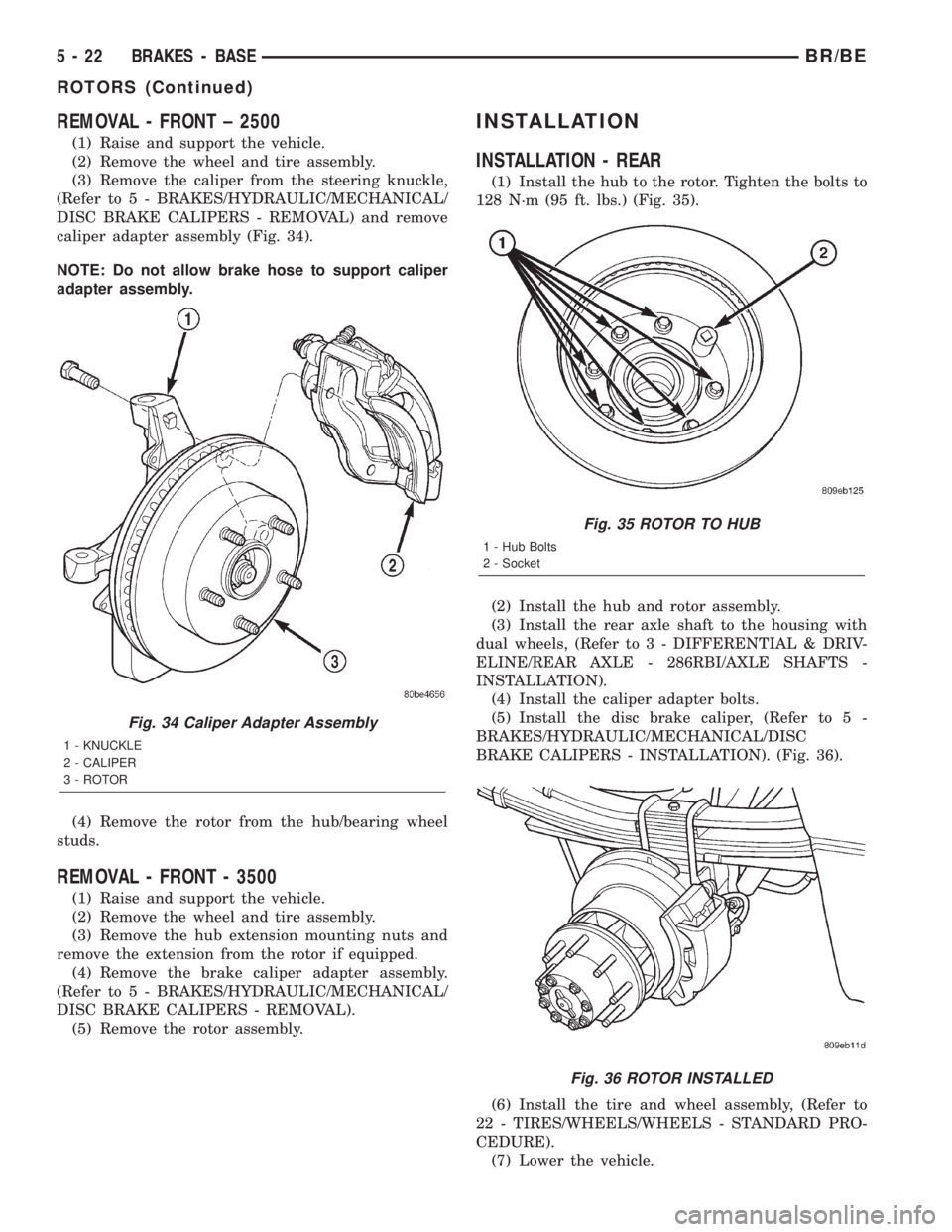
(3) Remove the caliper from the steering knuckle,
(Refer to 5 - BRAKES/HYDRAULIC/MECHANICAL/
DISC BRAKE CALIPERS - REMOVAL) and remove
caliper adapter assembly (Fig. 34).
NOTE: Do not allow brake hose to support caliper
adapter assembly.
(4) Remove the rotor from the hub/bearing wheel
studs.
REMOVAL - FRONT - 3500
(1) Raise and support the vehicle.
(2) Remove the wheel and tire assembly.
(3) Remove the hub extension mounting nuts and
remove the extension from the rotor if equipped.
(4) Remove the brake caliper adapter assembly.
(Refer to 5 - BRAKES/HYDRAULIC/MECHANICAL/
DISC BRAKE CALIPERS - REMOVAL).
(5) Remove the rotor assembly.
INSTALLATION
INSTALLATION - REAR
(1) Install the hub to the rotor. Tighten the bolts to
128 N´m (95 ft. lbs.) (Fig. 35).
(2) Install the hub and rotor assembly.
(3) Install the rear axle shaft to the housing with
dual wheels, (Refer to 3 - DIFFERENTIAL & DRIV-
ELINE/REAR AXLE - 286RBI/AXLE SHAFTS -
INSTALLATION).
(4) Install the caliper adapter bolts.
(5) Install the disc brake caliper, (Refer to 5 -
BRAKES/HYDRAULIC/MECHANICAL/DISC
BRAKE CALIPERS - INSTALLATION). (Fig. 36).
(6) Install the tire and wheel assembly, (Refer to
22 - TIRES/WHEELS/WHEELS - STANDARD PRO-
CEDURE).
(7) Lower the vehicle.
Fig. 34 Caliper Adapter Assembly
1 - KNUCKLE
2 - CALIPER
3 - ROTOR
Fig. 35 ROTOR TO HUB
1 - Hub Bolts
2 - Socket
Fig. 36 ROTOR INSTALLED
5 - 22 BRAKES - BASEBR/BE
ROTORS (Continued)
Page 212 of 2255
INSTALLATION - FRONT ± 2500
(1) On models with all-wheel antilock system
(ABS), check condition of tone wheel on hub/bearing.
If teeth on wheel are damaged, hub/bearing assembly
will have to be replaced (tone wheel is not serviced
separately).
(2) Install rotor onto the hub/bearing wheel studs.
(3) Install the caliper adapter assembly,(Refer to 5
- BRAKES/HYDRAULIC/MECHANICAL/DISC
BRAKE CALIPERS - INSTALLATION) and tighten
adapter bolts to:
²LD 1500: 176 N´m (130 ft lbs.)
²HD 2500: 285 N´m (210 ft lbs.)
(4) Install the wheel and tire assembly, (Refer to
22 - TIRES/WHEELS/WHEELS - STANDARD PRO-
CEDURE) and lower vehicle.
(5) Apply brakes several times to seat brake shoes.
Be sure to obtain firm pedal before moving vehicle.
INSTALLATION - FRONT - 3500
(1) Position the rotor on the hub/bearing.
(2) Install the brake caliper adapter assembly
(Refer to 5 - BRAKES/HYDRAULIC/MECHANICAL/
DISC BRAKE CALIPERS - INSTALLATION) and
tighten adapter bolts to 285 N´m (210 ft. lbs).
(3) Install the wheel and tire assemblies, (Refer to
22 - TIRES/WHEELS/WHEELS - STANDARD PRO-
CEDURE).
(4) Remove the support and lower the vehicle.
(5) Apply brakes several times to seat brake shoes
and caliper piston. Do not move vehicle until firm
brake pedal is obtained.
BRAKE PADS/SHOES
REMOVAL
REMOVAL - REAR
(1) Raise and support the vehicle.
(2) Remove the rear wheel and tire assemblies.
(3) Compress the caliper.
(4) Remove caliper mounting bolts
NOTE: Do not allow brake hose to support caliper
assembly.
(5) Remove the caliper, (Refer to 5 - BRAKES/HY-
DRAULIC/MECHANICAL/DISC BRAKE CALIPERS
- REMOVAL) and then tilt the top up and off the cal-
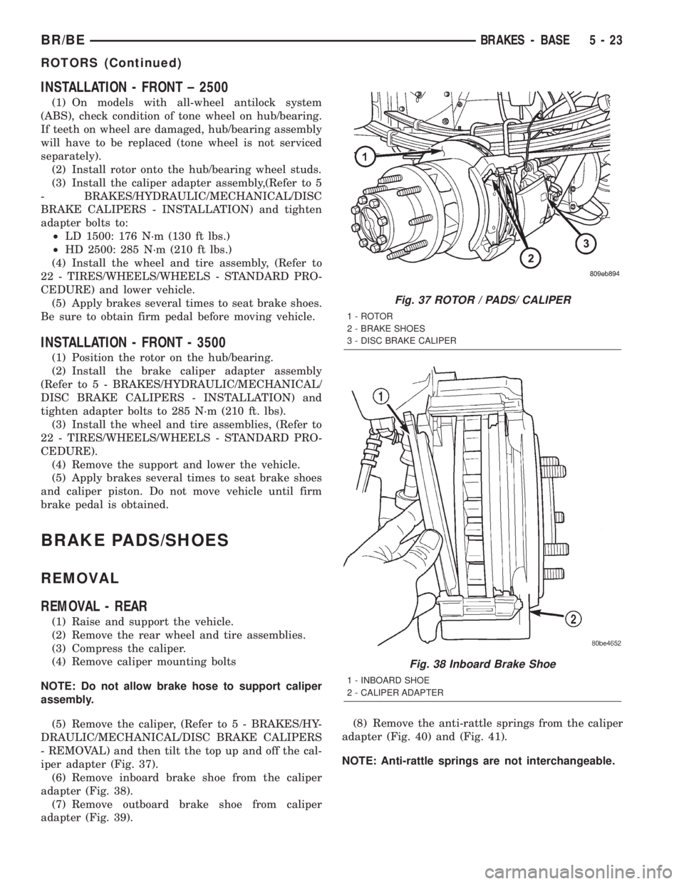
iper adapter (Fig. 37).
(6) Remove inboard brake shoe from the caliper
adapter (Fig. 38).
(7) Remove outboard brake shoe from caliper
adapter (Fig. 39).(8) Remove the anti-rattle springs from the caliper
adapter (Fig. 40) and (Fig. 41).
NOTE: Anti-rattle springs are not interchangeable.
Fig. 37 ROTOR / PADS/ CALIPER
1 - ROTOR
2 - BRAKE SHOES
3 - DISC BRAKE CALIPER
Fig. 38 Inboard Brake Shoe
1 - INBOARD SHOE
2 - CALIPER ADAPTER
BR/BEBRAKES - BASE 5 - 23
ROTORS (Continued)
Page 215 of 2255
(7) Install caliper, (Refer to 5 - BRAKES/HY-
DRAULIC/MECHANICAL/DISC BRAKE CALIPERS
- INSTALLATION) (Refer to 5 - BRAKES/HYDRAU-
LIC/MECHANICAL/DISC BRAKE CALIPERS -
INSTALLATION).
(8) Install wheel and tire assemblies and lower
vehicle, (Refer to 22 - TIRES/WHEELS/WHEELS -
STANDARD PROCEDURE).
(9) Apply brakes several times to seat caliper pis-
tons and brake shoes and obtain firm pedal.
(10) Top off master cylinder fluid level.
INSTALLATION - FRONT
(1) Bottom pistons in caliper bore with C-clamp.
Place an old brake shoe between a C-clamp and cal-
iper piston.
(2) Clean caliper mounting adapter and anti-rattle
springs.
(3) Lubricate anti-rattle springs with Mopar brake
grease.
(4) Install anti-rattle springs.
NOTE: Anti-rattle springs are not interchangeable.
(5) Install inboard brake shoe in adapter.
(6) Install outboard brake shoe in adapter.
(7) Tilt the bottom of the caliper over rotor and
under adapter. Then push the top of the caliper down
onto the adapter.
(8) Install caliper, (Refer to 5 - BRAKES/HY-
DRAULIC/MECHANICAL/DISC BRAKE CALIPERS
- INSTALLATION).
(9) Install wheel and tire assemblies and lower
vehicle, (Refer to 22 - TIRES/WHEELS/WHEELS -
STANDARD PROCEDURE).
(10) Apply brakes several times to seat caliper pis-
tons and brake shoes and obtain firm pedal.
(11) Top off master cylinder fluid level.
MASTER CYLINDER
DESCRIPTION
A two-piece master cylinder is used on all models.
The cylinder body containing the primary and sec-
ondary pistons is made of aluminum. The removable
fluid reservoir is made of nylon reinforced with glass
fiber. The reservoir stores reserve brake fluid for the
hydraulic brake circuits. The reservoir is the only
serviceable component.
The fluid compartments of the nylon reservoir are
interconnected to permit fluid level equalization.
However, the equalization feature does not affect cir-
cuit separation in the event of a front or rear brake
malfunction. The reservoir compartments will retain
enough fluid to operate the functioning hydraulic cir-
cuit.Care must be exercised when removing/installing
the master cylinder connecting lines. The threads in
the cylinder fluid ports can be damaged if care is not
exercised. Start all brake line fittings by hand to
avoid cross threading.
The cylinder reservoir can be replaced when neces-
sary. However, the aluminum body section of the
master cylinder is not a repairable component.
NOTE: If diagnosis indicates that an internal mal-
function has occurred, the aluminum body section
must be replaced as an assembly.
OPERATION
The master cylinder bore contains a primary and
secondary piston. The primary piston supplies
hydraulic pressure to the front brakes. The secondary
piston supplies hydraulic pressure to the rear brakes.
DIAGNOSIS AND TESTING - MASTER
CYLINDER/POWER BOOSTER
(1) Start engine and check booster vacuum hose
connections. A hissing noise indicates vacuum leak.
Correct any vacuum leak before proceeding.
(2) Stop engine and shift transmission into Neu-
tral.
(3) Pump brake pedal until all vacuum reserve in
booster is depleted.
(4) Press and hold brake pedal under light foot
pressure. The pedal should hold firm, if the pedal
falls away master cylinder is faulty (internal leak-
age).
(5) Start engine and note pedal action. It should
fall away slightly under light foot pressure then hold
firm. If no pedal action is discernible, power booster,
vacuum supply, or vacuum check valve is faulty. Pro-
ceed to the POWER BOOSTER VACUUM TEST.
(6) If the POWER BOOSTER VACUUM TEST
passes, rebuild booster vacuum reserve as follows:
Release brake pedal. Increase engine speed to 1500
rpm, close the throttle and immediately turn off igni-
tion to stop engine.
(7) Wait a minimum of 90 seconds and try brake
action again. Booster should provide two or more vac-
uum assisted pedal applications. If vacuum assist is
not provided, booster is faulty.
POWER BOOSTER VACUUM TEST
(1) Connect vacuum gauge to booster check valve
with short length of hose and T-fitting (Fig. 47).
(2) Start and run engine at curb idle speed for one
minute.
(3) Observe the vacuum supply. If vacuum supply
is not adequate, repair vacuum supply.
5 - 26 BRAKES - BASEBR/BE
BRAKE PADS/SHOES (Continued)
Page 220 of 2255

(7) Install the drum in hat assembly and verify
that the rotor rotates freely without drag.
(8) Install the wheel/tire assemblies, (Refer to 22 -
TIRES/WHEELS/WHEELS - STANDARD PROCE-
DURE).
(9) Lower the vehicle enough for access to the park
brake foot pedal. Then fully apply the park brakes.
NOTE: Leave park brakes applied until adjustment
is complete.
(10) Raise the vehicle again.
(11) Mark the tensioner rod 6.35 mm (1/4 in.) from
edge of the tensioner (Fig. 56).
(12) Tighten the adjusting nut on the tensioner rod
until the mark is no longer visible.
CAUTION: Do not loosen, or tighten the tensioner
adjusting nut for any reason after completing
adjustment.
(13) Lower the vehicle until the rear wheels are
15-20 cm (6-8 in.) off the shop floor.
(14) Release the park brake foot pedal and verify
that rear wheels rotate freely without drag. Then
lower the vehicle.
RELEASE HANDLE
REMOVAL
(1) Disconnect and isolate the battery negative
cable.
(2) Reach under the driver side outboard end of
the instrument panel to access and unsnap the plas-tic retainer clip that secures the park brake release
linkage rod to the park brake mechanism on the left
cowl side inner panel.
(3) Disengage the park brake release linkage rod
end from the park brake mechanism.
(4) Lift the park brake release handle to access
and unsnap the plastic retainer clip that secures the
park brake release linkage rod to the lever on the
back of the park brake release handle.
(5) Lower the park brake release handle and reach
under the driver side outboard end of the instrument
panel to disengage the park brake release linkage
rod end from the lever on the back of the park brake
release handle.
(6) Lift the park brake release handle to access the
handle mounting bracket.
(7) Using a trim stick or another suitable wide
flat-bladed tool, gently pry each of the park brake
release handle mounting bracket latch tabs away
from the retaining notches in the instrument panel
receptacle (Fig. 57) .
(8) With both of the park brake release handle
mounting bracket latches released, slide the handle
and bracket assembly down and out of the instru-
ment panel receptacle.
Fig. 56 Adjustment Mark
1 - TENSIONER CABLE BRACKET
2 - TENSIONER
3 - CABLE CONNECTOR
4 - 6.35mm
(1/4 IN.)
5 - ADJUSTER NUTFig. 57 Park Brake Release Handle Remove/Install
1 - CLIP
2 - ROD
3 - MOUNTING BRACKET
4 - TRIM STICK
5 - LATCH TABS
6 - PARK BRAKE RELEASE HANDLE
BR/BEBRAKES - BASE 5 - 31
CABLE TENSIONER (Continued)
Page 221 of 2255
INSTALLATION
(1) Position the park brake release handle to the
instrument panel.
(2) Slide the handle and bracket assembly up into
the instrument panel receptacle until both of the
park brake release handle mounting bracket latches
are engaged with the notches in the instrument
panel receptacle.
(3) Lower the park brake release handle and reach
under the driver side outboard end of the instrument
panel to engage the park brake release linkage rod
end with the lever on the back of the park brake
release handle.
(4) Lift the park brake release handle to access
and snap the plastic retainer clip that secures the
park brake release linkage rod to the lever on the
back of the park brake release handle over the link-
age rod.
(5) Reach under the driver side outboard end of
the instrument panel to access and engage the park
brake release linkage rod end to the park brake
mechanism.
(6) Snap the plastic retainer clip that secures the
park brake release linkage rod to the park brake
mechanism on the left cowl side inner panel over the
linkage rod.
(7) Reconnect the battery negative cable.
SHOES
REMOVAL
(1) Raise and support the vehicle.
(2) Remove the tire and wheel assembly.
(3) Remove the disc brake caliper, (Refer to 5 -
BRAKES/HYDRAULIC/MECHANICAL/DISC
BRAKE CALIPERS - REMOVAL)
(4) Remove the disc brake rotor, (Refer to 5 -
BRAKES/HYDRAULIC/MECHANICAL/ROTORS -
REMOVAL)
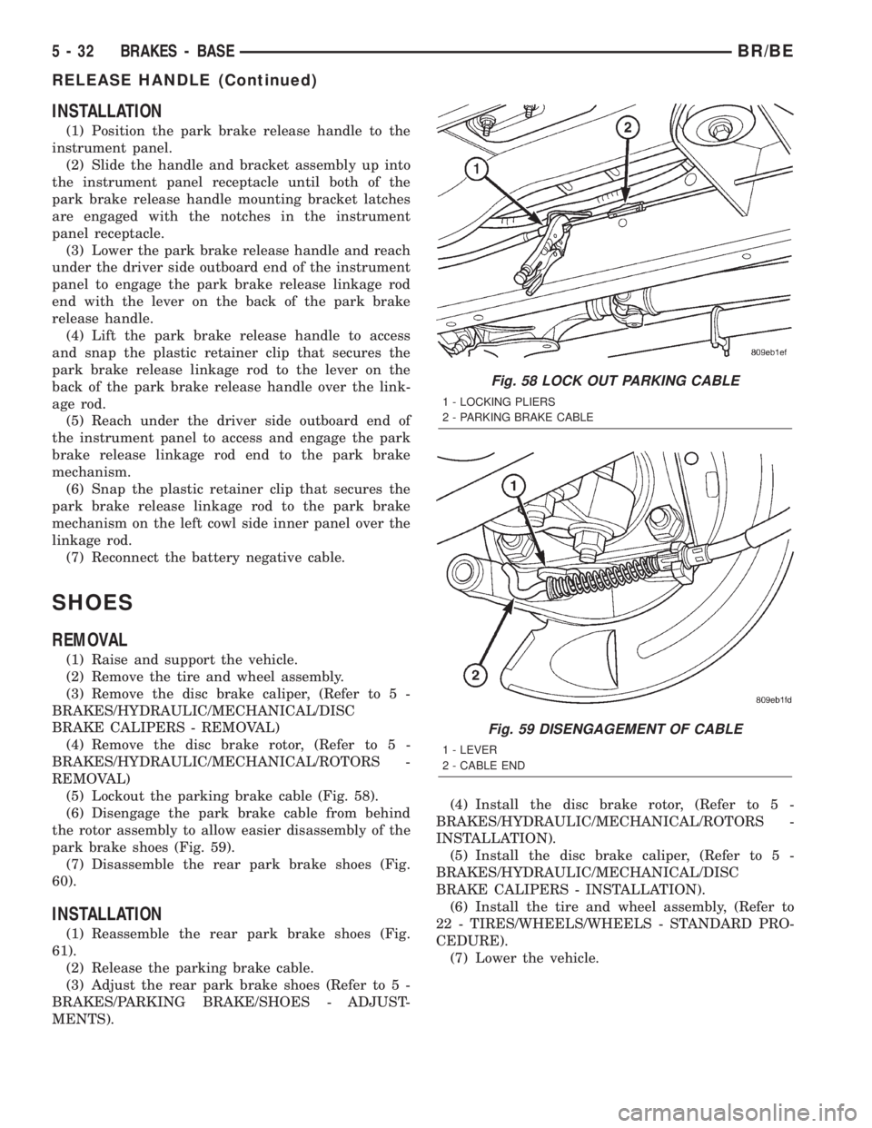
(5) Lockout the parking brake cable (Fig. 58).
(6) Disengage the park brake cable from behind
the rotor assembly to allow easier disassembly of the
park brake shoes (Fig. 59).
(7) Disassemble the rear park brake shoes (Fig.
60).
INSTALLATION
(1) Reassemble the rear park brake shoes (Fig.
61).
(2) Release the parking brake cable.
(3) Adjust the rear park brake shoes (Refer to 5 -
BRAKES/PARKING BRAKE/SHOES - ADJUST-
MENTS).(4) Install the disc brake rotor, (Refer to 5 -
BRAKES/HYDRAULIC/MECHANICAL/ROTORS -
INSTALLATION).
(5) Install the disc brake caliper, (Refer to 5 -
BRAKES/HYDRAULIC/MECHANICAL/DISC
BRAKE CALIPERS - INSTALLATION).
(6) Install the tire and wheel assembly, (Refer to
22 - TIRES/WHEELS/WHEELS - STANDARD PRO-
CEDURE).
(7) Lower the vehicle.
Fig. 58 LOCK OUT PARKING CABLE
1 - LOCKING PLIERS
2 - PARKING BRAKE CABLE
Fig. 59 DISENGAGEMENT OF CABLE
1 - LEVER
2 - CABLE END
5 - 32 BRAKES - BASEBR/BE
RELEASE HANDLE (Continued)
Page 376 of 2255

DIAGNOSIS AND TESTING - CCD DATA BUS
CCD BUS FAILURE
The CCD data bus can be monitored using the
DRBIIItscan tool. However, it is possible for the
data bus to pass all tests since the voltage parame-
ters will be in ªrangeª and false signals are being
sent. There are essentially 12 ªhard failuresª that
can occur with the CCD data bus:
²Bus Shorted to Battery
²Bus Shorted to 5 Volts
²Bus Shorted to Ground
²Bus (+) Shorted to Bus (±)
²Bus (±) and Bus (+) Open
²Bus (+) Open
²Bus (±) Open
²No Bus Bias
²Bus Bias Level Too High
²Bus Bias Level Too Low
²No Bus Termination
²Not Receiving Bus Messages Correctly
Refer to the appropriate diagnostic information for
details on how to diagnose these faults using a
DRBIIItscan tool.
BUS FAILURE VISUAL SYMPTOM DIAGNOSIS
The following visible symptoms or customer com-
plaints, alone or in combination, may indicate a CCD
data bus failure:
²Airbag Indicator and Malfunction Indicator
Lamp (MIL) Illuminated
²Instrument Cluster Gauges (All) Inoperative
²No Compass Mini-Trip Computer (CMTC) Oper-
ation (if equipped)
CONTROLLER ANTILOCK
BRAKE
DESCRIPTION
The Controller Antilock Brakes (CAB) is a micro-
processor which handles testing, monitoring and con-
trolling the ABS brake system operation (Fig. 10).
The CAB functions are:
²Perform self-test diagnostics.
²Monitor the RWAL brake system for proper oper-
ation.
²Control the RWAL valve solenoids.
NOTE: If the CAB needs to be replaced, the rear
axle type and tire revolutions per mile must be pro-
gramed into the new CAB. For axle type refer to
Group 3 Differential and Driveline. For tire revolu-
tions per mile,(Refer to 22 - TIRES/WHEELS/TIRES -
SPECIFICATIONS) . To program the CAB refer to the
Chassis Diagnostic Manual.
OPERATION
SYSTEM SELF-TEST
When the ignition switch is turned-on the micro-
processor RAM and ROM are tested. If an error
occurs during the test, a DTC will be set into the
RAM memory. However it is possible the DTC will
not be stored in memory if the error has occurred in
the RAM module were the DTC's are stored. Also it
is possible a DTC may not be stored if the error has
occurred in the ROM which signals the RAM to store
the DTC.
CAB INPUTS
The CAB continuously monitors the speed of the
differential ring gear by monitoring signals generated
by the rear wheel speed sensor. The CAB determines
a wheel locking tendency when it recognizes the ring
gear is decelerating too rapidly. The CAB monitors
the following inputs to determine when a wheel lock-
ing tendency may exists:
²Rear Wheel Speed Sensor
²Brake Lamp Switch
²Brake Warning Lamp Switch
²Reset Switch
²4WD Switch (If equipped)
CAB OUTPUTS
The CAB controls the following outputs for antilock
braking and brake warning information:
²RWAL Valve
²ABS Warning Lamp
²Brake Warning Lamp
REMOVAL
(1) Disconnect battery negative cable.
Fig. 10 RWAL CAB
1-RWALCAB
BR/BEELECTRONIC CONTROL MODULES 8E - 11
COMMUNICATION (Continued)