2002 DODGE RAM oil level
[x] Cancel search: oil levelPage 383 of 2255

OPERATION
OPERATION - PCM - GAS ENGINES
The PCM operates the fuel system. The PCM is a
pre-programmed, triple microprocessor digital com-
puter. It regulates ignition timing, air-fuel ratio,
emission control devices, charging system, certain
transmission features, speed control, air conditioning
compressor clutch engagement and idle speed. The
PCM can adapt its programming to meet changing
operating conditions.
The PCM receives input signals from various
switches and sensors. Based on these inputs, the
PCM regulates various engine and vehicle operations
through different system components. These compo-
nents are referred to as Powertrain Control Module
(PCM) Outputs. The sensors and switches that pro-
vide inputs to the PCM are considered Powertrain
Control Module (PCM) Inputs.
The PCM adjusts ignition timing based upon
inputs it receives from sensors that react to: engine
rpm, manifold absolute pressure, engine coolant tem-
perature, throttle position, transmission gear selec-
tion (automatic transmission), vehicle speed and the
brake switch.
The PCM adjusts idle speed based on inputs it
receives from sensors that react to: throttle position,
vehicle speed, transmission gear selection, engine
coolant temperature and from inputs it receives from
the air conditioning clutch switch and brake switch.
Based on inputs that it receives, the PCM adjusts
ignition coil dwell. The PCM also adjusts the gener-
ator charge rate through control of the generator
field and provides speed control operation.
NOTE: PCM Inputs:
²A/C request (if equipped with factory A/C)
²A/C select (if equipped with factory A/C)
²Auto shutdown (ASD) sense
²Battery temperature
²Battery voltage
²Brake switch
²CCD bus (+) circuits
²CCD bus (-) circuits
²Camshaft position sensor signal
²Crankshaft position sensor
²Data link connection for DRB scan tool
²Engine coolant temperature sensor
²Fuel level
²Generator (battery voltage) output
²Ignition circuit sense (ignition switch in on/off/
crank/run position)
²Intake manifold air temperature sensor
²Leak detection pump (switch) sense (if equipped)
²Manifold absolute pressure (MAP) sensor²Oil pressure
²Output shaft speed sensor
²Overdrive/override switch
²Oxygen sensors
²Park/neutral switch (auto. trans. only)
²Power ground
²Sensor return
²Signal ground
²Speed control multiplexed single wire input
²Throttle position sensor
²Transmission governor pressure sensor
²Transmission temperature sensor
²Vehicle speed inputs from ABS or RWAL system
NOTE: PCM Outputs:
²A/C clutch relay
²Auto shutdown (ASD) relay
²CCD bus (+/-) circuits for: speedometer, voltme-
ter, fuel gauge, oil pressure gauge/lamp, engine temp.
gauge and speed control warn. lamp
²Data link connection for DRB scan tool
²EGR valve control solenoid (if equipped)
²EVAP canister purge solenoid
²Five volt sensor supply (primary)
²Five volt sensor supply (secondary)
²Fuel injectors
²Fuel pump relay
²Generator field driver (-)
²Generator field driver (+)
²Generator lamp (if equipped)
²Idle air control (IAC) motor
²Ignition coil
²Leak detection pump (if equipped)
²Malfunction indicator lamp (Check engine lamp).
Driven through CCD circuits.
²Overdrive indicator lamp (if equipped)
²Service Reminder Indicator (SRI) Lamp (MAINT
REQ'D lamp). Driven through CCD circuits.
²Speed control vacuum solenoid
²Speed control vent solenoid
²Tachometer (if equipped). Driven through CCD
circuits.
²Transmission convertor clutch circuit
²Transmission 3±4 shift solenoid
²Transmission relay
²Transmission temperature lamp (if equipped)
²Transmission variable force solenoid
OPERATION - DIESEL
Two different control modules are used: The Pow-
ertrain Control Module (PCM), and the Engine Con-
trol Module (ECM). The ECMcontrolsthe fuel
system. The PCMdoes not controlthe fuel system.
The PCM's main function is to control: the vehicle
charging system, speed control system, transmission,
air conditioning system and certain bussed messages.
8E - 18 ELECTRONIC CONTROL MODULESBR/BE
POWERTRAIN CONTROL MODULE (Continued)
Page 384 of 2255

The PCM can adapt its programming to meet
changing operating conditions.
The PCM receives input signals from various
switches and sensors. Based on these inputs, the
PCM regulates various engine and vehicle operations
through different system components. These compo-
nents are referred to asPCM Outputs.The sensors
and switches that provide inputs to the PCM are con-
sideredPCM Inputs.
NOTE: PCM Inputs:
²A/C request (if equipped with factory A/C)
²A/C select (if equipped with factory A/C)
²Accelerator Pedal Position Sensor (APPS) output
from ECM
²Auto shutdown (ASD) relay sense
²Battery temperature sensor
²Battery voltage
²Brake switch
²CCD bus (+) circuits
²CCD bus (-) circuits
²Crankshaft Position Sensor (CKP) output from
ECM
²Data link connection for DRB scan tool
²Fuel level sensor
²Generator (battery voltage) output
²Ignition sense
²Output shaft speed sensor
²Overdrive/override switch
²Park/neutral switch (auto. trans. only)
²Power ground
²Sensor return
²Signal ground
²Speed control resume switch
²Speed control set switch
²Speed control on/off switch
²Transmission governor pressure sensor
²Transmission temperature sensor
²Vehicle speed inputs from ABS or RWAL system
NOTE: PCM Outputs:
After inputs are received by the PCM, certain sen-
sors, switches and components are controlled or reg-
ulated by the PCM. These are consideredPCM
Outputs.These outputs are for:
²A/C clutch relay and A/C clutch
²Auto shutdown (ASD) relay
²CCD bus (+/-) circuits for: speedometer, voltme-
ter, fuel gauge, oil pressure gauge/lamp, engine temp.
gauge and speed control warn. lamp
²Data link connection for DRB scan tool
²Five volt sensor supply
²Generator field driver (-)
²Generator field driver (+)
²Generator lamp (if equipped)²Malfunction indicator lamp (Check engine lamp)
²Overdrive warning lamp (if equipped)
²Speed control vacuum solenoid
²Speed control vent solenoid
²Tachometer (if equipped)
²Transmission convertor clutch circuit
²Transmission 3±4 shift solenoid
²Transmission relay
²Transmission temperature lamp (if equipped)
²Transmission variable force solenoid (governor
sol.)
OPERATION - 5 VOLT SUPPLIES
Primary 5±volt supply:
²supplies the required 5 volt power source to the
Crankshaft Position (CKP) sensor.
²supplies the required 5 volt power source to the
Camshaft Position (CMP) sensor.
²supplies a reference voltage for the Manifold
Absolute Pressure (MAP) sensor.
²supplies a reference voltage for the Throttle
Position Sensor (TPS) sensor.
Secondary 5±volt supply:
²supplies the required 5 volt power source to the
oil pressure sensor.
²supplies the required 5 volt power source for the
Vehicle Speed Sensor (VSS) (if equipped).
²supplies the 5 volt power source to the transmis-
sion pressure sensor (if equipped with an RE auto-
matic transmission).
OPERATION - IGNITION CIRCUIT SENSE
The ignition circuit sense input tells the PCM the
ignition switch has energized the ignition circuit.
Battery voltage is also supplied to the PCM
through the ignition switch when the ignition is in
the RUN or START position. This is referred to as
the9ignition sense9circuit and is used to9wake up9
the PCM. Voltage on the ignition input can be as low
as 6 volts and the PCM will still function. Voltage is
supplied to this circuit to power the PCM's 8-volt reg-
ulator and to allow the PCM to perform fuel, ignition
and emissions control functions.
REMOVAL
USE THE DRB SCAN TOOL TO REPROGRAM
THE NEW POWERTRAIN CONTROL MODULE
(PCM) WITH THE VEHICLES ORIGINAL IDEN-
TIFICATION NUMBER (VIN) AND THE VEHI-
CLES ORIGINAL MILEAGE. IF THIS STEP IS
NOT DONE, A DIAGNOSTIC TROUBLE CODE
(DTC) MAY BE SET.
The PCM is located in the engine compartment
(Fig. 18).
BR/BEELECTRONIC CONTROL MODULES 8E - 19
POWERTRAIN CONTROL MODULE (Continued)
Page 533 of 2255
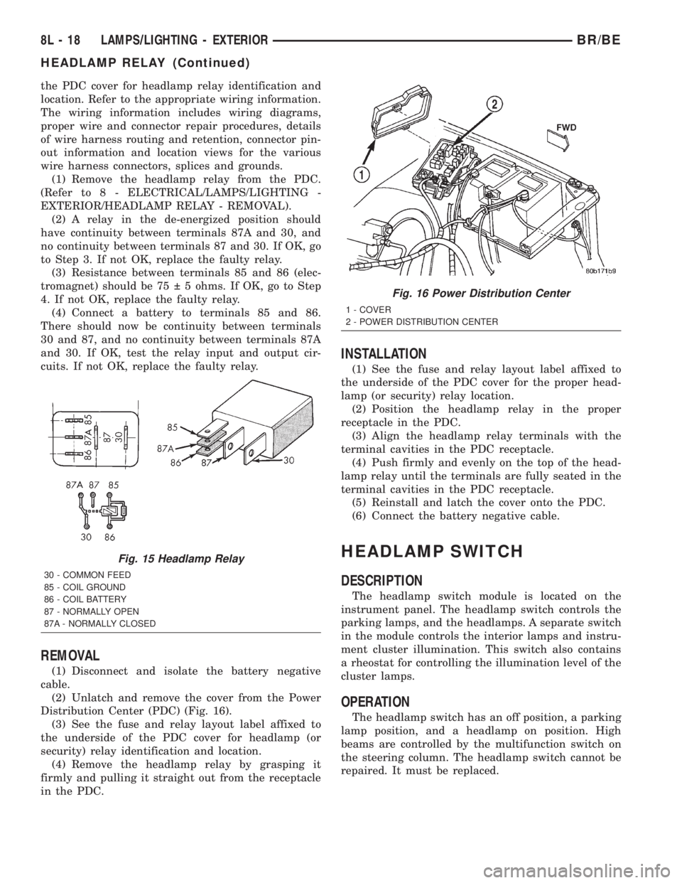
the PDC cover for headlamp relay identification and
location. Refer to the appropriate wiring information.
The wiring information includes wiring diagrams,
proper wire and connector repair procedures, details
of wire harness routing and retention, connector pin-
out information and location views for the various
wire harness connectors, splices and grounds.
(1) Remove the headlamp relay from the PDC.
(Refer to 8 - ELECTRICAL/LAMPS/LIGHTING -
EXTERIOR/HEADLAMP RELAY - REMOVAL).
(2) A relay in the de-energized position should
have continuity between terminals 87A and 30, and
no continuity between terminals 87 and 30. If OK, go
to Step 3. If not OK, replace the faulty relay.
(3) Resistance between terminals 85 and 86 (elec-
tromagnet) should be 75 5 ohms. If OK, go to Step
4. If not OK, replace the faulty relay.
(4) Connect a battery to terminals 85 and 86.
There should now be continuity between terminals
30 and 87, and no continuity between terminals 87A
and 30. If OK, test the relay input and output cir-
cuits. If not OK, replace the faulty relay.
REMOVAL
(1) Disconnect and isolate the battery negative
cable.
(2) Unlatch and remove the cover from the Power
Distribution Center (PDC) (Fig. 16).
(3) See the fuse and relay layout label affixed to
the underside of the PDC cover for headlamp (or
security) relay identification and location.
(4) Remove the headlamp relay by grasping it
firmly and pulling it straight out from the receptacle
in the PDC.
INSTALLATION
(1) See the fuse and relay layout label affixed to
the underside of the PDC cover for the proper head-
lamp (or security) relay location.
(2) Position the headlamp relay in the proper
receptacle in the PDC.
(3) Align the headlamp relay terminals with the
terminal cavities in the PDC receptacle.
(4) Push firmly and evenly on the top of the head-
lamp relay until the terminals are fully seated in the
terminal cavities in the PDC receptacle.
(5) Reinstall and latch the cover onto the PDC.
(6) Connect the battery negative cable.
HEADLAMP SWITCH
DESCRIPTION
The headlamp switch module is located on the
instrument panel. The headlamp switch controls the
parking lamps, and the headlamps. A separate switch
in the module controls the interior lamps and instru-
ment cluster illumination. This switch also contains
a rheostat for controlling the illumination level of the
cluster lamps.
OPERATION
The headlamp switch has an off position, a parking
lamp position, and a headlamp on position. High
beams are controlled by the multifunction switch on
the steering column. The headlamp switch cannot be
repaired. It must be replaced.
Fig. 15 Headlamp Relay
30 - COMMON FEED
85 - COIL GROUND
86 - COIL BATTERY
87 - NORMALLY OPEN
87A - NORMALLY CLOSED
Fig. 16 Power Distribution Center
1 - COVER
2 - POWER DISTRIBUTION CENTER
8L - 18 LAMPS/LIGHTING - EXTERIORBR/BE
HEADLAMP RELAY (Continued)
Page 1007 of 2255
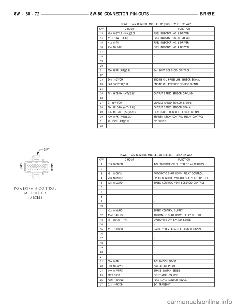
POWERTRAIN CONTROL MODULE C2 (GAS) - WHITE 32 WAY
CAV CIRCUIT FUNCTION
13 K28 18GY/LB (5.9L)(8.0L) FUEL INJECTOR NO. 8 DRIVER
14 K116 18WT (8.0L) FUEL INJECTOR NO. 10 DRIVER
15 K12 18TN FUEL INJECTOR NO. 2 DRIVER
16 K14 18LB/BR FUEL INJECTOR NO. 4 DRIVER
17 - -
18 - -
19 - -
20 - -
21 T60 18BR (A/T)(5.9L) 3-4 SHIFT SOLENOID CONTROL
22 - -
23 G60 18GY/OR ENGINE OIL PRESSURE SENSOR SIGNAL
23 G60 18GY/OR(5.9L) ENGINE OIL PRESURE SENSOR SIGNAL
24 - -
25 T13 18DB/BK (A/T)(5.9L) OUTPUT SPEED SENSOR GROUND
26 - -
27 G7 18WT/OR VEHICLE SPEED SENSOR SIGNAL
28 T14 18LG/BK (A/T)(5.9L) OUTPUT SPEED SENSOR SIGNAL
29 T25 18LG/WT (A/T)(5.9L) GOVERNOR PRESSURE SENSOR SIGNAL
30 K30 18PK (A/T)(5.9L) TRANSMISSION CONTROL RELAY CONTROL
31 K7 18OR (A/T)(5.9L) 5V SUPPLY
32 - -
POWERTRAIN CONTROL MODULE C3 (DIESEL) - GRAY 32 WAY
CAV CIRCUIT FUNCTION
1 C13 18DB/OR A/C COMPRESSOR CLUTCH RELAY CONTROL
2- -
3 K51 18DB/YL AUTOMATIC SHUT DOWN RELAY CONTROL
4 V36 18TN/RD SPEED CONTROL VACUUM SOLENOID CONTROL
5 V35 18LG/RD SPEED CONTROL VENT SOLENOID CONTROL
6- -
7- -
8- -
9- -
10 - -
11 V32 18YL/RD SPEED CONTROL SUPPLY
12 A142 14DG/OR AUTOMATIC SHUT DOWN RELAY OUTPUT
13 T6 18OR/WT (A/T) OVERDRIVE OFF SWITCH SENSE
14 - -
15 K118 18PK/YL BATTERY TEMPERATURE SENSOR SIGNAL
16 - -
17 - -
18 - -
19 - -
20 - -
21 - -
22 C20 18BR A/C SWITCH SENSE
23 C90 18LG/WT A/C SELECT INPUT
24 V40 18WT/PK BRAKE SWITCH SENSE
25 T125 18DB GENERATOR SOURCE
26 K226 18DB/WT FUEL LEVEL SENSOR SIGNAL
27 D21 18PK/DB SCI TRANSMIT
8W - 80 - 72 8W-80 CONNECTOR PIN-OUTSBR/BE
Page 1081 of 2255
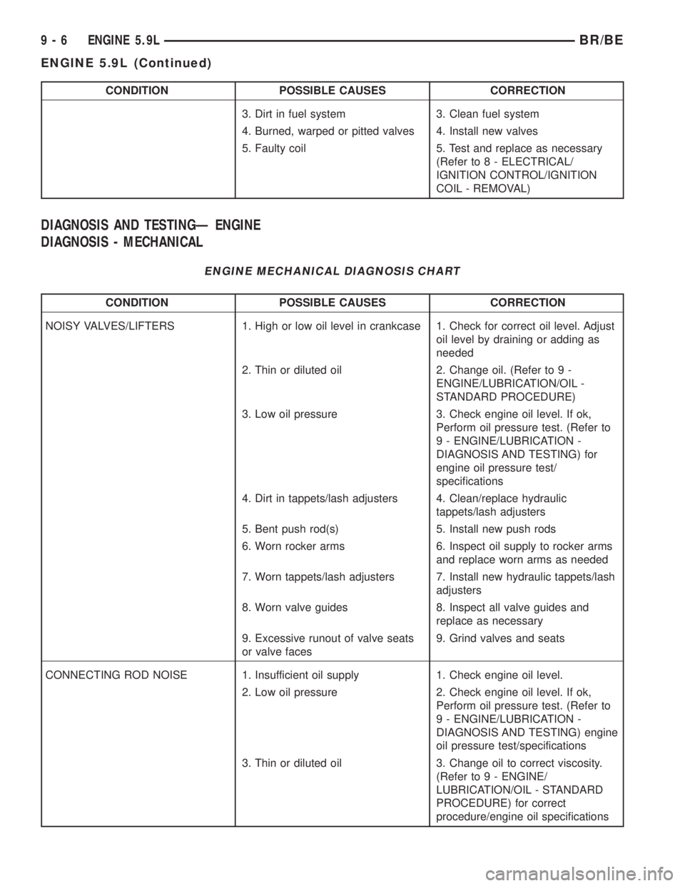
CONDITION POSSIBLE CAUSES CORRECTION
3. Dirt in fuel system 3. Clean fuel system
4. Burned, warped or pitted valves 4. Install new valves
5. Faulty coil 5. Test and replace as necessary
(Refer to 8 - ELECTRICAL/
IGNITION CONTROL/IGNITION
COIL - REMOVAL)
DIAGNOSIS AND TESTINGÐ ENGINE
DIAGNOSIS - MECHANICAL
ENGINE MECHANICAL DIAGNOSIS CHART
CONDITION POSSIBLE CAUSES CORRECTION
NOISY VALVES/LIFTERS 1. High or low oil level in crankcase 1. Check for correct oil level. Adjust
oil level by draining or adding as
needed
2. Thin or diluted oil 2. Change oil. (Refer to 9 -
ENGINE/LUBRICATION/OIL -
STANDARD PROCEDURE)
3. Low oil pressure 3. Check engine oil level. If ok,
Perform oil pressure test. (Refer to
9 - ENGINE/LUBRICATION -
DIAGNOSIS AND TESTING) for
engine oil pressure test/
specifications
4. Dirt in tappets/lash adjusters 4. Clean/replace hydraulic
tappets/lash adjusters
5. Bent push rod(s) 5. Install new push rods
6. Worn rocker arms 6. Inspect oil supply to rocker arms
and replace worn arms as needed
7. Worn tappets/lash adjusters 7. Install new hydraulic tappets/lash
adjusters
8. Worn valve guides 8. Inspect all valve guides and
replace as necessary
9. Excessive runout of valve seats
or valve faces9. Grind valves and seats
CONNECTING ROD NOISE 1. Insufficient oil supply 1. Check engine oil level.
2. Low oil pressure 2. Check engine oil level. If ok,
Perform oil pressure test. (Refer to
9 - ENGINE/LUBRICATION -
DIAGNOSIS AND TESTING) engine
oil pressure test/specifications
3. Thin or diluted oil 3. Change oil to correct viscosity.
(Refer to 9 - ENGINE/
LUBRICATION/OIL - STANDARD
PROCEDURE) for correct
procedure/engine oil specifications
9 - 6 ENGINE 5.9LBR/BE
ENGINE 5.9L (Continued)
Page 1082 of 2255
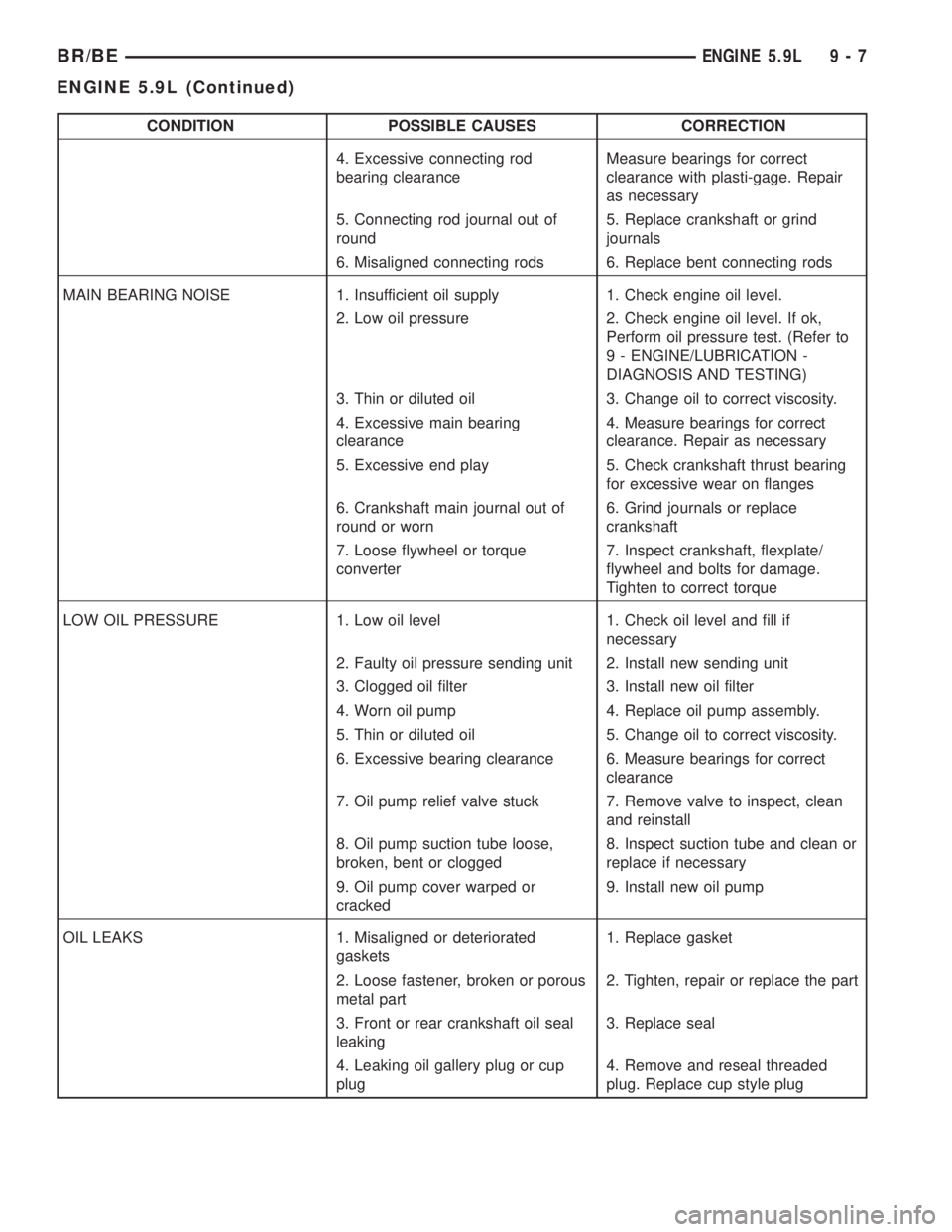
CONDITION POSSIBLE CAUSES CORRECTION
4. Excessive connecting rod
bearing clearanceMeasure bearings for correct
clearance with plasti-gage. Repair
as necessary
5. Connecting rod journal out of
round5. Replace crankshaft or grind
journals
6. Misaligned connecting rods 6. Replace bent connecting rods
MAIN BEARING NOISE 1. Insufficient oil supply 1. Check engine oil level.
2. Low oil pressure 2. Check engine oil level. If ok,
Perform oil pressure test. (Refer to
9 - ENGINE/LUBRICATION -
DIAGNOSIS AND TESTING)
3. Thin or diluted oil 3. Change oil to correct viscosity.
4. Excessive main bearing
clearance4. Measure bearings for correct
clearance. Repair as necessary
5. Excessive end play 5. Check crankshaft thrust bearing
for excessive wear on flanges
6. Crankshaft main journal out of
round or worn6. Grind journals or replace
crankshaft
7. Loose flywheel or torque
converter7. Inspect crankshaft, flexplate/
flywheel and bolts for damage.
Tighten to correct torque
LOW OIL PRESSURE 1. Low oil level 1. Check oil level and fill if
necessary
2. Faulty oil pressure sending unit 2. Install new sending unit
3. Clogged oil filter 3. Install new oil filter
4. Worn oil pump 4. Replace oil pump assembly.
5. Thin or diluted oil 5. Change oil to correct viscosity.
6. Excessive bearing clearance 6. Measure bearings for correct
clearance
7. Oil pump relief valve stuck 7. Remove valve to inspect, clean
and reinstall
8. Oil pump suction tube loose,
broken, bent or clogged8. Inspect suction tube and clean or
replace if necessary
9. Oil pump cover warped or
cracked9. Install new oil pump
OIL LEAKS 1. Misaligned or deteriorated
gaskets1. Replace gasket
2. Loose fastener, broken or porous
metal part2. Tighten, repair or replace the part
3. Front or rear crankshaft oil seal
leaking3. Replace seal
4. Leaking oil gallery plug or cup
plug4. Remove and reseal threaded
plug. Replace cup style plug
BR/BEENGINE 5.9L 9 - 7
ENGINE 5.9L (Continued)
Page 1083 of 2255
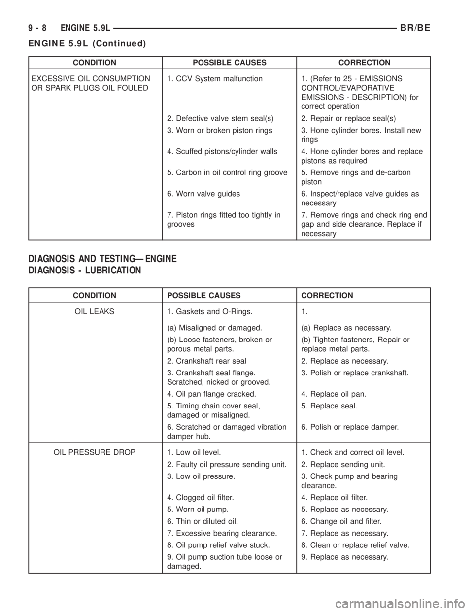
CONDITION POSSIBLE CAUSES CORRECTION
EXCESSIVE OIL CONSUMPTION
OR SPARK PLUGS OIL FOULED1. CCV System malfunction 1. (Refer to 25 - EMISSIONS
CONTROL/EVAPORATIVE
EMISSIONS - DESCRIPTION) for
correct operation
2. Defective valve stem seal(s) 2. Repair or replace seal(s)
3. Worn or broken piston rings 3. Hone cylinder bores. Install new
rings
4. Scuffed pistons/cylinder walls 4. Hone cylinder bores and replace
pistons as required
5. Carbon in oil control ring groove 5. Remove rings and de-carbon
piston
6. Worn valve guides 6. Inspect/replace valve guides as
necessary
7. Piston rings fitted too tightly in
grooves7. Remove rings and check ring end
gap and side clearance. Replace if
necessary
DIAGNOSIS AND TESTINGÐENGINE
DIAGNOSIS - LUBRICATION
CONDITION POSSIBLE CAUSES CORRECTION
OIL LEAKS 1. Gaskets and O-Rings. 1.
(a) Misaligned or damaged. (a) Replace as necessary.
(b) Loose fasteners, broken or
porous metal parts.(b) Tighten fasteners, Repair or
replace metal parts.
2. Crankshaft rear seal 2. Replace as necessary.
3. Crankshaft seal flange.
Scratched, nicked or grooved.3. Polish or replace crankshaft.
4. Oil pan flange cracked. 4. Replace oil pan.
5. Timing chain cover seal,
damaged or misaligned.5. Replace seal.
6. Scratched or damaged vibration
damper hub.6. Polish or replace damper.
OIL PRESSURE DROP 1. Low oil level. 1. Check and correct oil level.
2. Faulty oil pressure sending unit. 2. Replace sending unit.
3. Low oil pressure. 3. Check pump and bearing
clearance.
4. Clogged oil filter. 4. Replace oil filter.
5. Worn oil pump. 5. Replace as necessary.
6. Thin or diluted oil. 6. Change oil and filter.
7. Excessive bearing clearance. 7. Replace as necessary.
8. Oil pump relief valve stuck. 8. Clean or replace relief valve.
9. Oil pump suction tube loose or
damaged.9. Replace as necessary.
9 - 8 ENGINE 5.9LBR/BE
ENGINE 5.9L (Continued)
Page 1084 of 2255
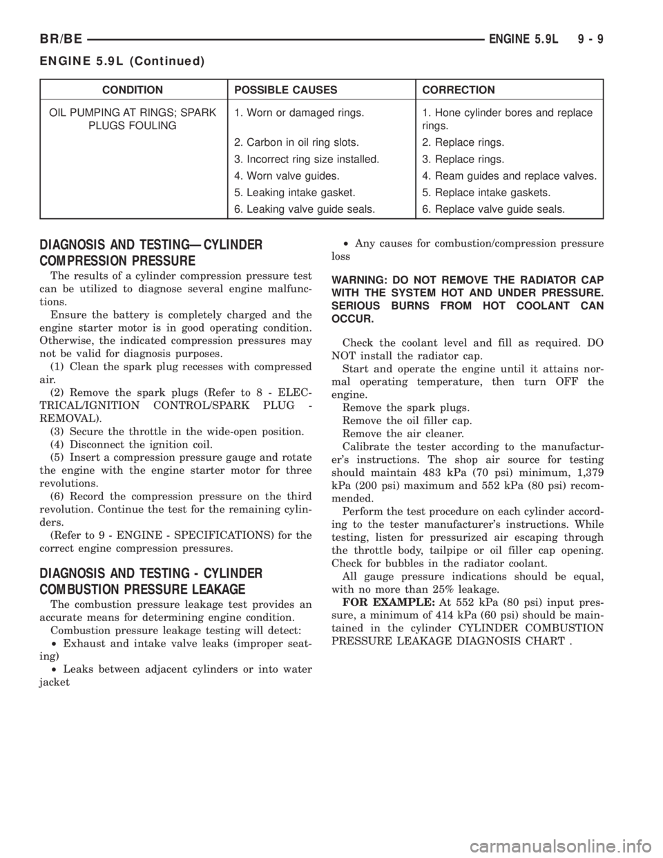
CONDITION POSSIBLE CAUSES CORRECTION
OIL PUMPING AT RINGS; SPARK
PLUGS FOULING1. Worn or damaged rings. 1. Hone cylinder bores and replace
rings.
2. Carbon in oil ring slots. 2. Replace rings.
3. Incorrect ring size installed. 3. Replace rings.
4. Worn valve guides. 4. Ream guides and replace valves.
5. Leaking intake gasket. 5. Replace intake gaskets.
6. Leaking valve guide seals. 6. Replace valve guide seals.
DIAGNOSIS AND TESTINGÐCYLINDER
COMPRESSION PRESSURE
The results of a cylinder compression pressure test
can be utilized to diagnose several engine malfunc-
tions.
Ensure the battery is completely charged and the
engine starter motor is in good operating condition.
Otherwise, the indicated compression pressures may
not be valid for diagnosis purposes.
(1) Clean the spark plug recesses with compressed
air.
(2) Remove the spark plugs (Refer to 8 - ELEC-
TRICAL/IGNITION CONTROL/SPARK PLUG -
REMOVAL).
(3) Secure the throttle in the wide-open position.
(4) Disconnect the ignition coil.
(5) Insert a compression pressure gauge and rotate
the engine with the engine starter motor for three
revolutions.
(6) Record the compression pressure on the third
revolution. Continue the test for the remaining cylin-
ders.
(Refer to 9 - ENGINE - SPECIFICATIONS) for the
correct engine compression pressures.
DIAGNOSIS AND TESTING - CYLINDER
COMBUSTION PRESSURE LEAKAGE
The combustion pressure leakage test provides an
accurate means for determining engine condition.
Combustion pressure leakage testing will detect:
²Exhaust and intake valve leaks (improper seat-
ing)
²Leaks between adjacent cylinders or into water
jacket²Any causes for combustion/compression pressure
loss
WARNING: DO NOT REMOVE THE RADIATOR CAP
WITH THE SYSTEM HOT AND UNDER PRESSURE.
SERIOUS BURNS FROM HOT COOLANT CAN
OCCUR.
Check the coolant level and fill as required. DO
NOT install the radiator cap.
Start and operate the engine until it attains nor-
mal operating temperature, then turn OFF the
engine.
Remove the spark plugs.
Remove the oil filler cap.
Remove the air cleaner.
Calibrate the tester according to the manufactur-
er's instructions. The shop air source for testing
should maintain 483 kPa (70 psi) minimum, 1,379
kPa (200 psi) maximum and 552 kPa (80 psi) recom-
mended.
Perform the test procedure on each cylinder accord-
ing to the tester manufacturer's instructions. While
testing, listen for pressurized air escaping through
the throttle body, tailpipe or oil filler cap opening.
Check for bubbles in the radiator coolant.
All gauge pressure indications should be equal,
with no more than 25% leakage.
FOR EXAMPLE:At 552 kPa (80 psi) input pres-
sure, a minimum of 414 kPa (60 psi) should be main-
tained in the cylinder CYLINDER COMBUSTION
PRESSURE LEAKAGE DIAGNOSIS CHART .
BR/BEENGINE 5.9L 9 - 9
ENGINE 5.9L (Continued)