2002 DODGE RAM oil level
[x] Cancel search: oil levelPage 1237 of 2255
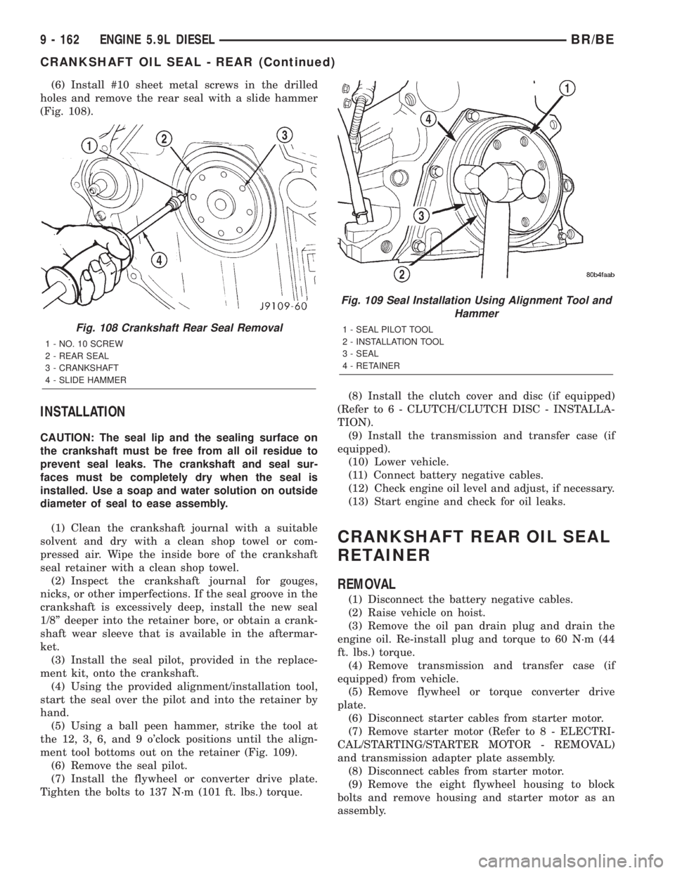
(6) Install #10 sheet metal screws in the drilled
holes and remove the rear seal with a slide hammer
(Fig. 108).
INSTALLATION
CAUTION: The seal lip and the sealing surface on
the crankshaft must be free from all oil residue to
prevent seal leaks. The crankshaft and seal sur-
faces must be completely dry when the seal is
installed. Use a soap and water solution on outside
diameter of seal to ease assembly.
(1) Clean the crankshaft journal with a suitable
solvent and dry with a clean shop towel or com-
pressed air. Wipe the inside bore of the crankshaft
seal retainer with a clean shop towel.
(2) Inspect the crankshaft journal for gouges,
nicks, or other imperfections. If the seal groove in the
crankshaft is excessively deep, install the new seal
1/8º deeper into the retainer bore, or obtain a crank-
shaft wear sleeve that is available in the aftermar-
ket.
(3) Install the seal pilot, provided in the replace-
ment kit, onto the crankshaft.
(4) Using the provided alignment/installation tool,
start the seal over the pilot and into the retainer by
hand.
(5) Using a ball peen hammer, strike the tool at
the 12, 3, 6, and 9 o'clock positions until the align-
ment tool bottoms out on the retainer (Fig. 109).
(6) Remove the seal pilot.
(7) Install the flywheel or converter drive plate.
Tighten the bolts to 137 N´m (101 ft. lbs.) torque.(8) Install the clutch cover and disc (if equipped)
(Refer to 6 - CLUTCH/CLUTCH DISC - INSTALLA-
TION).
(9) Install the transmission and transfer case (if
equipped).
(10) Lower vehicle.
(11) Connect battery negative cables.
(12) Check engine oil level and adjust, if necessary.
(13) Start engine and check for oil leaks.
CRANKSHAFT REAR OIL SEAL
RETAINER
REMOVAL
(1) Disconnect the battery negative cables.
(2) Raise vehicle on hoist.
(3) Remove the oil pan drain plug and drain the
engine oil. Re-install plug and torque to 60 N´m (44
ft. lbs.) torque.
(4) Remove transmission and transfer case (if
equipped) from vehicle.
(5) Remove flywheel or torque converter drive
plate.
(6) Disconnect starter cables from starter motor.
(7) Remove starter motor (Refer to 8 - ELECTRI-
CAL/STARTING/STARTER MOTOR - REMOVAL)
and transmission adapter plate assembly.
(8) Disconnect cables from starter motor.
(9) Remove the eight flywheel housing to block
bolts and remove housing and starter motor as an
assembly.
Fig. 108 Crankshaft Rear Seal Removal
1 - NO. 10 SCREW
2 - REAR SEAL
3 - CRANKSHAFT
4 - SLIDE HAMMER
Fig. 109 Seal Installation Using Alignment Tool and
Hammer
1 - SEAL PILOT TOOL
2 - INSTALLATION TOOL
3 - SEAL
4 - RETAINER
9 - 162 ENGINE 5.9L DIESELBR/BE
CRANKSHAFT OIL SEAL - REAR (Continued)
Page 1253 of 2255

DIAGNOSIS AND TESTINGÐENGINE OIL
PRESSURE
(1) Remove the engine oil pressure sensor and
install Oil Pressure Line and Gauge Tool C-3292 with
a suitable adapter.
(2) Start engine and warm to operating tempera-
ture.
(3) Record engine oil pressure and compare with
engine oil pressure chart.
CAUTION: If engine oil pressure is zero at idle, DO
NOT RUN THE ENGINE.
Engine Oil Pressure (MIN)
At Idle 103.4 kPa (15 psi)
At 2000 rpm 310.2 kPa (45 psi)
If minimum engine oil pressure is below these
ranges, (Refer to 9 - ENGINE - DIAGNOSIS AND
TESTING).
(4) Remove oil pressure gauge and install the oil
pressure sensor. Tighten the sensor to 16 N´m (144
in. lbs.) torque.
OIL
STANDARD PROCEDURE
STANDARD PROCEDURE - ENGINE OIL LEVEL
CAUTION: Do not overfill crankcase with engine oil,
oil foaming and oil pressure loss can result.
To ensure proper lubrication of an engine, the
engine oil must be maintained at an acceptable level.
The acceptable oil level is in the SAFE RANGE on
the engine oil dipstick (Fig. 150).
Unless the engine has exhibited loss of oil pres-
sure, run the engine for about five minutes before
checking oil level. Checking engine oil level of a cold
engine is not accurate.
(1) Position vehicle on level surface.(2) With engine OFF, allow approximately ten min-
utes for oil to settle to bottom of crankcase, remove
engine oil dipstick.
(3) Wipe dipstick clean.
(4) Replace dipstick and verify it is seated in the
tube.
(5) Remove dipstick, with handle held above the
tip, take oil level reading.
(6) Add oil only if level is below the SAFE RANGE
area on the dipstick.
(7) Replace dipstick
STANDARD PROCEDURE - ENGINE OIL
SERVICE
WARNING: HOT OIL CAN CAUSE PERSONAL
INJURY.
NOTE: Change engine oil and filter at intervals
specified in the owner's manual.
(1) Operate the engine until the water tempera-
ture reaches 60ÉC (140ÉF). Shut the engine off.
(2) Use a container that can hold at least 14 liters
(15 quarts) to hold the used oil. Remove the oil drain
plug and drain the used engine oil into the container.
1 - ROCKER ARM
2 - ROCKER SHAFT
3 - PEDESTAL
4 - FROM MAIN OIL RIFLE
5 - TO VALVE TRAIN
6 - MAIN OIL RIFLE
7 - FROM MAIN OIL RIFLE
8 - TO CAMSHAFT9 - TO PISTON COOLING NOZZLE
10 - FROM OIL COOLER
11 - CRANKSHAFT MAIN JOURNAL
12 - ROD JOURNAL
13 - TO ROD BEARING
14 - MAIN OIL RIFLE
Fig. 150 Oil Level Indicator (Dipstick)
1 - ADD OIL MARK
2 - O-RING
3 - SAFE RANGE
9 - 178 ENGINE 5.9L DIESELBR/BE
LUBRICATION (Continued)
Page 1254 of 2255
(3) Always check the condition of the used oil. This
can give you an indication of engine problems that
might exist.
²Thin, black oil indicates fuel dilution.
²Milky discoloration indicates coolant dilution.
(4) Clean the area around the oil filter head.
Remove the filter (Refer to 9 - ENGINE/LUBRICA-
TION/OIL FILTER - REMOVAL).
(5) Install new oil filter (Refer to 9 - ENGINE/LU-
BRICATION/OIL FILTER - INSTALLATION).
(6) Clean the drain plug and the sealing surface of
the pan. Check the condition of the threads and seal-
ing surface on the oil pan and drain plug.
(7) Install the drain plug. Tighten the plug to 50
N´m (37 ft. lbs.) torque.
(8) Use only High-Quality Multi-Viscosity lubricat-
ing oil in the Cummins Turbo Diesel engine. Choose
the correct oil for the operating conditions (Refer to
LUBRICATION & MAINTENANCE/FLUID TYPES -
DESCRIPTION).
(9) Fill the engine with the correct grade of new oil
(Refer to LUBRICATION & MAINTENANCE/FLUID
CAPACITIES - SPECIFICATIONS).
(10) Start the engine and operate it at idle for sev-
eral minutes. Check for leaks at the filter and drain
plug.
(11) Stop engine. Wait several minutes to allow the
oil to drain back to the pan and check the level
again.
USED ENGINE OIL DISPOSAL Care should be
exercised when disposing of used engine oil after
it has been drained from a vehicle's engine.
OIL COOLER & LINES
CLEANING AND INSPECTION
Clean the sealing surfaces.
Apply 483 kPa (70 psi) air pressure to the element
to check for leaks. If the element leaks, replace the
element.
OIL FILTER
REMOVAL
(1) Clean the area around the oil filter head.
Remove the filter using a 90-95 mm filter wrench.
(2) Clean the gasket surface of the filter head. The
filter canister O-Ring seal can stick on the filter
head. Make sure it is removed.
INSTALLATION
(1) Fill the oil filter element with clean oil before
installation. Use the same type oil that will be used
in the engine.
(2) Apply a light film of lubricating oil to the seal-
ing surface before installing the filter.
CAUTION: Mechanical over-tightening may distort
the threads or damage the filter element seal.
(3) Install the filter until it contacts the sealing
surface of the oil filter adapter. Tighten filter an
additional ó turn.
OIL PAN
REMOVAL
(1) Disconnect the battery negative cables.
(2) Raise vehicle on hoist.
(3) Remove transmission and transfer case (if
equipped).
(4) Remove flywheel.
(5) Disconnect starter cables from starter motor.
(6) Remove starter motor (Refer to 8 - ELECTRI-
CAL/STARTING/STARTER MOTOR - REMOVAL)
and transmission adapter plate assembly.
WARNING: HOT OIL CAN CAUSE PERSONAL
INJURY.
(7) Drain the engine oil (Refer to 9 - ENGINE/LU-
BRICATION/OIL - STANDARD PROCEDURE).
(8) Install the oil pan drain plug with a new seal-
ing washer and tighten to 60 N´m (44 ft. lbs.) torque.
(9) Remove oil pan bolts, break the pan to block
seal, and lower pan slightly and remove oil suction
tube fasteners.
(10) Remove oil pan and suction tube (Fig. 151).
CLEANING
Remove all gasket material from the oil pan and
cylinder block sealing surfaces. Extra effort may be
required around T-joint areas. Clean oil pan and
flush suction tube with a suitable solvent.
INSPECTION
Inspect the oil pan, suction tube, and tube braces
for cracks and damage. Replace any defective compo-
nent. Inspect the oil drain plug and drain hole
threads. Inspect the oil pan sealing surface for
straightness. Repair any minor imperfections with a
ball-peen hammer. Do not attempt to repair an oil
pan by welding.
BR/BEENGINE 5.9L DIESEL 9 - 179
OIL (Continued)
Page 1255 of 2255
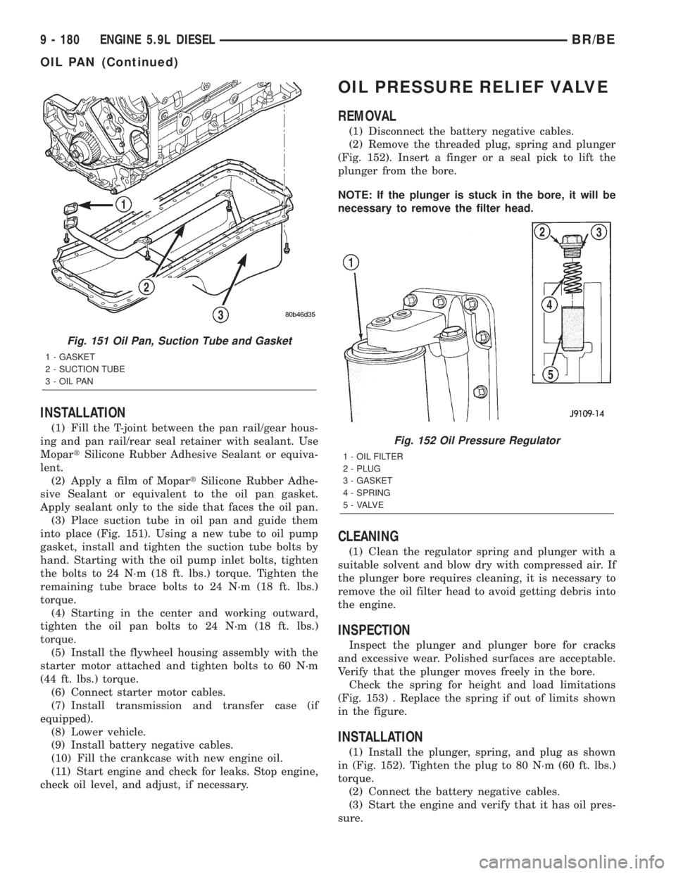
INSTALLATION
(1) Fill the T-joint between the pan rail/gear hous-
ing and pan rail/rear seal retainer with sealant. Use
MopartSilicone Rubber Adhesive Sealant or equiva-
lent.
(2) Apply a film of MopartSilicone Rubber Adhe-
sive Sealant or equivalent to the oil pan gasket.
Apply sealant only to the side that faces the oil pan.
(3) Place suction tube in oil pan and guide them
into place (Fig. 151). Using a new tube to oil pump
gasket, install and tighten the suction tube bolts by
hand. Starting with the oil pump inlet bolts, tighten
the bolts to 24 N´m (18 ft. lbs.) torque. Tighten the
remaining tube brace bolts to 24 N´m (18 ft. lbs.)
torque.
(4) Starting in the center and working outward,
tighten the oil pan bolts to 24 N´m (18 ft. lbs.)
torque.
(5) Install the flywheel housing assembly with the
starter motor attached and tighten bolts to 60 N´m
(44 ft. lbs.) torque.
(6) Connect starter motor cables.
(7) Install transmission and transfer case (if
equipped).
(8) Lower vehicle.
(9) Install battery negative cables.
(10) Fill the crankcase with new engine oil.
(11) Start engine and check for leaks. Stop engine,
check oil level, and adjust, if necessary.
OIL PRESSURE RELIEF VALVE
REMOVAL
(1) Disconnect the battery negative cables.
(2) Remove the threaded plug, spring and plunger
(Fig. 152). Insert a finger or a seal pick to lift the
plunger from the bore.
NOTE: If the plunger is stuck in the bore, it will be
necessary to remove the filter head.
CLEANING
(1) Clean the regulator spring and plunger with a
suitable solvent and blow dry with compressed air. If
the plunger bore requires cleaning, it is necessary to
remove the oil filter head to avoid getting debris into
the engine.
INSPECTION
Inspect the plunger and plunger bore for cracks
and excessive wear. Polished surfaces are acceptable.
Verify that the plunger moves freely in the bore.
Check the spring for height and load limitations
(Fig. 153) . Replace the spring if out of limits shown
in the figure.
INSTALLATION
(1) Install the plunger, spring, and plug as shown
in (Fig. 152). Tighten the plug to 80 N´m (60 ft. lbs.)
torque.
(2) Connect the battery negative cables.
(3) Start the engine and verify that it has oil pres-
sure.
Fig. 151 Oil Pan, Suction Tube and Gasket
1 - GASKET
2 - SUCTION TUBE
3 - OIL PAN
Fig. 152 Oil Pressure Regulator
1 - OIL FILTER
2 - PLUG
3 - GASKET
4 - SPRING
5 - VALVE
9 - 180 ENGINE 5.9L DIESELBR/BE
OIL PAN (Continued)
Page 1311 of 2255
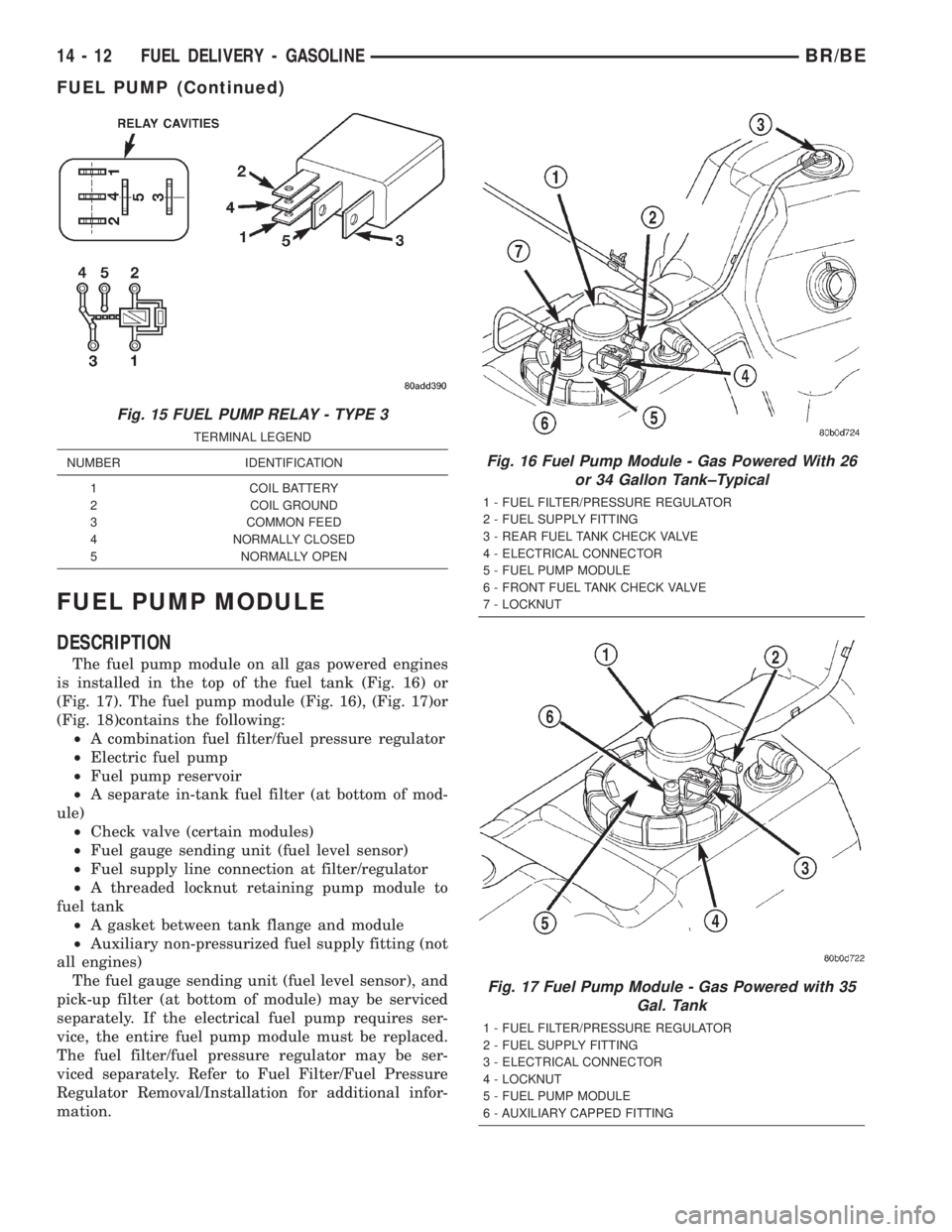
FUEL PUMP MODULE
DESCRIPTION
The fuel pump module on all gas powered engines
is installed in the top of the fuel tank (Fig. 16) or
(Fig. 17). The fuel pump module (Fig. 16), (Fig. 17)or
(Fig. 18)contains the following:
²A combination fuel filter/fuel pressure regulator
²Electric fuel pump
²Fuel pump reservoir
²A separate in-tank fuel filter (at bottom of mod-
ule)
²Check valve (certain modules)
²Fuel gauge sending unit (fuel level sensor)
²Fuel supply line connection at filter/regulator
²A threaded locknut retaining pump module to
fuel tank
²A gasket between tank flange and module
²Auxiliary non-pressurized fuel supply fitting (not
all engines)
The fuel gauge sending unit (fuel level sensor), and
pick-up filter (at bottom of module) may be serviced
separately. If the electrical fuel pump requires ser-
vice, the entire fuel pump module must be replaced.
The fuel filter/fuel pressure regulator may be ser-
viced separately. Refer to Fuel Filter/Fuel Pressure
Regulator Removal/Installation for additional infor-
mation.
Fig. 15 FUEL PUMP RELAY - TYPE 3
TERMINAL LEGEND
NUMBER IDENTIFICATION
1 COIL BATTERY
2 COIL GROUND
3 COMMON FEED
4 NORMALLY CLOSED
5 NORMALLY OPEN
Fig. 16 Fuel Pump Module - Gas Powered With 26
or 34 Gallon Tank±Typical
1 - FUEL FILTER/PRESSURE REGULATOR
2 - FUEL SUPPLY FITTING
3 - REAR FUEL TANK CHECK VALVE
4 - ELECTRICAL CONNECTOR
5 - FUEL PUMP MODULE
6 - FRONT FUEL TANK CHECK VALVE
7 - LOCKNUT
Fig. 17 Fuel Pump Module - Gas Powered with 35
Gal. Tank
1 - FUEL FILTER/PRESSURE REGULATOR
2 - FUEL SUPPLY FITTING
3 - ELECTRICAL CONNECTOR
4 - LOCKNUT
5 - FUEL PUMP MODULE
6 - AUXILIARY CAPPED FITTING
14 - 12 FUEL DELIVERY - GASOLINEBR/BE
FUEL PUMP (Continued)
Page 1381 of 2255
CAUTION: Be sure that the high-pressure fuel lines
are installed in the same order that they were
removed.
(1) Lubricate threads of injector line fittings with
clean engine oil.
(2) Loosen, but do not remove, all fuel line support
bracket bolts.
(3) Installrearinjection line bundle beginning
with cylinder head (fuel injector) connections, fol-
lowed by injection pump connections. Tighten all fit-
tings finger tight.
(4) Tighten fittings at fuel injector ends for cylin-
ders number 6 and 5 to 38 N´m (28 ft. lbs.) torque.
Do not tighten number 3 line at this time. It
will be tightened during bleeding procedure.
(5) Tighten 3 fittings at fuel injection pump ends
to 24 N´m (18 ft. lbs.) torque.
(6) Installfrontinjection line bundle beginning
with cylinder head (fuel injector) connections, fol-
lowed by injection pump connections. Tighten all fit-
tings finger tight.
(7) Tighten fitting at fuel injector end for cylinder
number 2 to 38 N´m (28 ft. lbs.) torque.Do not
tighten lines number 1 or 4 at this time. They
will be tightened during bleeding procedure.
(8) Tighten remaining 3 fittings at fuel injection
pump ends to 24 N´m (18 ft. lbs.) torque.
(9) Install fuel line support bracket bolts to intake
manifold and tighten to 24 N´m (18 ft. lbs.) torque.
CAUTION: Be sure fuel lines are not contacting
each other or any other component. Noise will
result.
(10) Install engine lifting bracket at rear of intake
manifold. Tighten 2 bolts to 77 N´m (57 ft. lbs.)
torque.
(11) Install cable bracket housing/cable assembly
and tighten 3 mounting bolts to 24 N´m (18 ft. lbs.)
torque.
(12) Clean any old gasket material below and
above intake manifold air heater element block. Also
clean mating areas at intake manifold and air intake
housing.
(13) Using new gaskets, position intake manifold
air heater element block to engine.
(14) Install air intake housing and position ground
cable. Install 4 mounting bolts and tighten to 24 N´m
(18 ft. lbs.) torque.
(15) Install air tube (intake manifold-to-charge air
cooler) (Fig. 49). Tighten clamps to 8 N´m (72 in. lbs.)
torque.
(16) Install engine oil dipstick tube support mount-
ing bolt and tighten to 24 N´m (18 ft. lbs.) torque.
(17) Install engine oil dipstick to engine.(18) Connect 2 electrical cables to cable mounting
studs.
(19) Connect electrical connector to bottom of
APPS by pushing connector upward until it snaps
into position.
(20) Connect wiring harness (clip) at bottom of
Accelerator Pedal Position Sensor (APPS) mounting
bracket (Fig. 48).
(21) Connect front wiring clip (Fig. 49) to cable
bracket housing.
(22) Install cable cover (Fig. 47).
(23) Connect both negative battery cables to both
batteries.
(24) Bleed air from fuel system. Do this at fuel
injector ends of lines. Use cylinders numbers 1, 3 and
4 for bleeding. (Refer to 14 - FUEL SYSTEM/FUEL
DELIVERY - STANDARD PROCEDURE). After
bleeding, tighten fittings to 38 N´m (28 ft. lbs.)
torque.
(25) Check lines/fittings for leaks.
FUEL TANK
DESCRIPTION - DIESEL FUEL TANK
The fuel tank is similar to the tank used with gas-
oline powered models. The tank is equipped with a
separate fuel return line and a different fuel tank
module for diesel powered models. A fuel tank
mounted, electric fuel pump is not used with diesel
powered models. Refer to Fuel Tank Module for addi-
tional information.
For removal and installation procedures, refer to
Fuel Tank - Gasoline Engines.
FUEL TANK MODULE
DESCRIPTION
An electric fuel pump isnot usedin the fuel tank
module for diesel powered engines. Fuel is supplied
by the engine mounted fuel transfer pump and the
fuel injection pump.
The fuel tank module is installed in the top of the
fuel tank (Fig. 56). The fuel tank module (Fig. 56)
contains the following components:
²Fuel reservoir
²A separate in-tank fuel filter
²Rollover valve
²Fuel gauge sending unit (fuel level sensor)
²Fuel supply line connection
²Fuel return line connection
²Auxiliary non-pressurized fuel supply fitting
OPERATION
Refer to Fuel Gauge Sending Unit.
14 - 82 FUEL DELIVERY - DIESELBR/BE
FUEL LINES (Continued)
Page 1442 of 2255
PUMP
TABLE OF CONTENTS
page page
PUMP
DESCRIPTION.........................33
OPERATION...........................33
DIAGNOSIS AND TESTING - PUMP LEAKAGE . 33
STANDARD PROCEDURE
STANDARD PROCEDURE - POWER
STEERING PUMP - INITIAL OPERATION....33
STANDARD PROCEDURE - FLUSHING
POWER STEERING SYSTEM............34
REMOVAL
REMOVAL - GASOLINE ENGINE..........35
REMOVAL - DIESEL ENGINE............36
INSTALLATION
INSTALLATION - GASOLINE ENGINE......37INSTALLATION - DIESEL ENGINE.........37
SPECIAL TOOLS
POWER STEERING PUMP..............38
PULLEY
REMOVAL.............................38
INSTALLATION.........................39
HOSES - PRESSURE
DESCRIPTION.........................39
OPERATION...........................39
HOSES - RETURN
DESCRIPTION.........................39
OPERATION...........................39
PUMP
DESCRIPTION
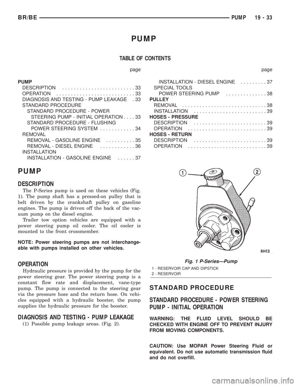
The P-Series pump is used on these vehicles (Fig.
1). The pump shaft has a pressed-on pulley that is
belt driven by the crankshaft pulley on gasoline
engines. The pump is driven off the back of the vac-
uum pump on the diesel engine.
Trailer tow option vehicles are equipped with a
power steering pump oil cooler. The oil cooler is
mounted to the front crossmember.
NOTE: Power steering pumps are not interchange-
able with pumps installed on other vehicles.
OPERATION
Hydraulic pressure is provided by the pump for the
power steering gear. The power steering pump is a
constant flow rate and displacement, vane-type
pump. The pump is connected to the steering gear
via the pressure hose and the return hose. On vehi-
cles equipped with a hydraulic booster, the pump
supplies the hydraulic pressure for the booster.
DIAGNOSIS AND TESTING - PUMP LEAKAGE
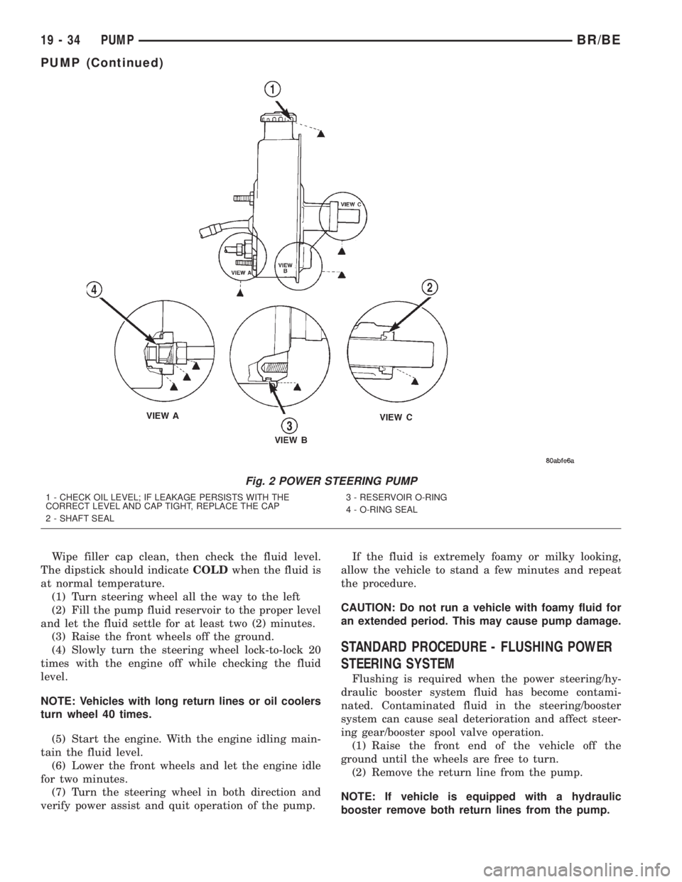
(1) Possible pump leakage areas. (Fig. 2).
STANDARD PROCEDURE
STANDARD PROCEDURE - POWER STEERING
PUMP - INITIAL OPERATION
WARNING: THE FLUID LEVEL SHOULD BE
CHECKED WITH ENGINE OFF TO PREVENT INJURY
FROM MOVING COMPONENTS.
CAUTION: Use MOPAR Power Steering Fluid or
equivalent. Do not use automatic transmission fluid
and do not overfill.
Fig. 1 P-SeriesÐPump
1 - RESERVOIR CAP AND DIPSTICK
2 - RESERVOIR
BR/BEPUMP 19 - 33
Page 1443 of 2255
Wipe filler cap clean, then check the fluid level.
The dipstick should indicateCOLDwhen the fluid is
at normal temperature.
(1) Turn steering wheel all the way to the left
(2) Fill the pump fluid reservoir to the proper level
and let the fluid settle for at least two (2) minutes.
(3) Raise the front wheels off the ground.
(4) Slowly turn the steering wheel lock-to-lock 20
times with the engine off while checking the fluid
level.
NOTE: Vehicles with long return lines or oil coolers
turn wheel 40 times.
(5) Start the engine. With the engine idling main-
tain the fluid level.
(6) Lower the front wheels and let the engine idle
for two minutes.
(7) Turn the steering wheel in both direction and
verify power assist and quit operation of the pump.If the fluid is extremely foamy or milky looking,
allow the vehicle to stand a few minutes and repeat
the procedure.
CAUTION: Do not run a vehicle with foamy fluid for
an extended period. This may cause pump damage.
STANDARD PROCEDURE - FLUSHING POWER
STEERING SYSTEM
Flushing is required when the power steering/hy-
draulic booster system fluid has become contami-
nated. Contaminated fluid in the steering/booster
system can cause seal deterioration and affect steer-
ing gear/booster spool valve operation.
(1) Raise the front end of the vehicle off the
ground until the wheels are free to turn.
(2) Remove the return line from the pump.
NOTE: If vehicle is equipped with a hydraulic
booster remove both return lines from the pump.
Fig. 2 POWER STEERING PUMP
1 - CHECK OIL LEVEL; IF LEAKAGE PERSISTS WITH THE
CORRECT LEVEL AND CAP TIGHT, REPLACE THE CAP
2 - SHAFT SEAL3 - RESERVOIR O-RING
4 - O-RING SEAL
19 - 34 PUMPBR/BE
PUMP (Continued)