2002 DODGE RAM oil level
[x] Cancel search: oil levelPage 1111 of 2255
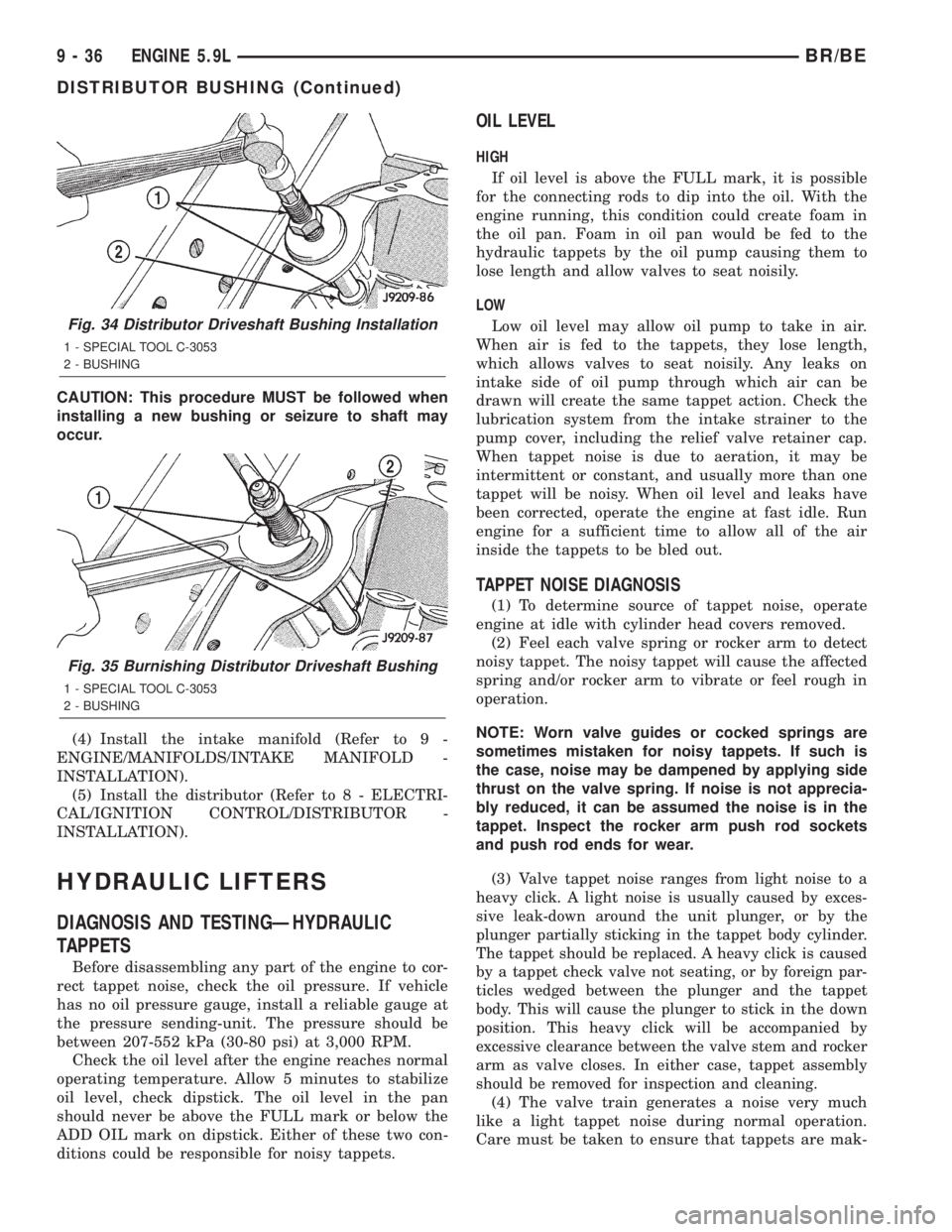
CAUTION: This procedure MUST be followed when
installing a new bushing or seizure to shaft may
occur.
(4) Install the intake manifold (Refer to 9 -
ENGINE/MANIFOLDS/INTAKE MANIFOLD -
INSTALLATION).
(5) Install the distributor (Refer to 8 - ELECTRI-
CAL/IGNITION CONTROL/DISTRIBUTOR -
INSTALLATION).
HYDRAULIC LIFTERS
DIAGNOSIS AND TESTINGÐHYDRAULIC
TAPPETS
Before disassembling any part of the engine to cor-
rect tappet noise, check the oil pressure. If vehicle
has no oil pressure gauge, install a reliable gauge at
the pressure sending-unit. The pressure should be
between 207-552 kPa (30-80 psi) at 3,000 RPM.
Check the oil level after the engine reaches normal
operating temperature. Allow 5 minutes to stabilize
oil level, check dipstick. The oil level in the pan
should never be above the FULL mark or below the
ADD OIL mark on dipstick. Either of these two con-
ditions could be responsible for noisy tappets.
OIL LEVEL
HIGH
If oil level is above the FULL mark, it is possible
for the connecting rods to dip into the oil. With the
engine running, this condition could create foam in
the oil pan. Foam in oil pan would be fed to the
hydraulic tappets by the oil pump causing them to
lose length and allow valves to seat noisily.
LOW
Low oil level may allow oil pump to take in air.
When air is fed to the tappets, they lose length,
which allows valves to seat noisily. Any leaks on
intake side of oil pump through which air can be
drawn will create the same tappet action. Check the
lubrication system from the intake strainer to the
pump cover, including the relief valve retainer cap.
When tappet noise is due to aeration, it may be
intermittent or constant, and usually more than one
tappet will be noisy. When oil level and leaks have
been corrected, operate the engine at fast idle. Run
engine for a sufficient time to allow all of the air
inside the tappets to be bled out.
TAPPET NOISE DIAGNOSIS
(1) To determine source of tappet noise, operate
engine at idle with cylinder head covers removed.
(2) Feel each valve spring or rocker arm to detect
noisy tappet. The noisy tappet will cause the affected
spring and/or rocker arm to vibrate or feel rough in
operation.
NOTE: Worn valve guides or cocked springs are
sometimes mistaken for noisy tappets. If such is
the case, noise may be dampened by applying side
thrust on the valve spring. If noise is not apprecia-
bly reduced, it can be assumed the noise is in the
tappet. Inspect the rocker arm push rod sockets
and push rod ends for wear.
(3)
Valve tappet noise ranges from light noise to a
heavy click. A light noise is usually caused by exces-
sive leak-down around the unit plunger, or by the
plunger partially sticking in the tappet body cylinder.
The tappet should be replaced. A heavy click is caused
by a tappet check valve not seating, or by foreign par-
ticles wedged between the plunger and the tappet
body. This will cause the plunger to stick in the down
position. This heavy click will be accompanied by
excessive clearance between the valve stem and rocker
arm as valve closes. In either case, tappet assembly
should be removed for inspection and cleaning.
(4) The valve train generates a noise very much
like a light tappet noise during normal operation.
Care must be taken to ensure that tappets are mak-
Fig. 34 Distributor Driveshaft Bushing Installation
1 - SPECIAL TOOL C-3053
2 - BUSHING
Fig. 35 Burnishing Distributor Driveshaft Bushing
1 - SPECIAL TOOL C-3053
2 - BUSHING
9 - 36 ENGINE 5.9LBR/BE
DISTRIBUTOR BUSHING (Continued)
Page 1120 of 2255
(4) If dye is not observed, drive the vehicle at var-
ious speeds for approximately 24km (15 miles), and
repeat previous step.
(5) If the oil leak source is not positively identified
at this time, proceed with the air leak detection test
method as follows:
(6) Disconnect the breather cap to air cleaner hose
at the breather cap end. Cap or plug breather cap
nipple.
(7) Remove the PCV valve from the cylinder head
cover. Cap or plug the PCV valve grommet.
(8) Attach an air hose with pressure gauge and
regulator to the dipstick tube.
CAUTION: Do not subject the engine assembly to
more than 20.6 kpa (3 PSI) of test pressure.
(9) Gradually apply air pressure from 1 psi to 2.5
psi maximum while applying soapy water at the sus-
pected source. Adjust the regulator to the suitable
test pressure that provide the best bubbles which
will pinpoint the leak source. If the oil leak is
detected and identified, repair per service manual
procedures.
(10) If the leakage occurs at the rear oil seal area,
refer to the section, Inspection for Rear Seal Area
Leak.
(11) If no leaks are detected, turn off the air sup-
ply and remove the air hose and all plugs and caps.
Install the PCV valve and breather cap hose. Proceed
to next step.
(12) Clean the oil off the suspect oil leak area
using a suitable solvent. Drive the vehicle at various
speeds approximately 24 km (15 miles). Inspect the
engine for signs of an oil leak by using a black light.
DIAGNOSIS AND TESTINGÐENGINE OIL
PRESSURE
(1) Remove oil pressure sending unit.
(2) Install Oil Pressure Line and Gauge Tool
C-3292. Start engine and record pressure. (Refer to 9
- ENGINE - SPECIFICATIONS).
OIL
STANDARD PROCEDURE - ENGINE OIL
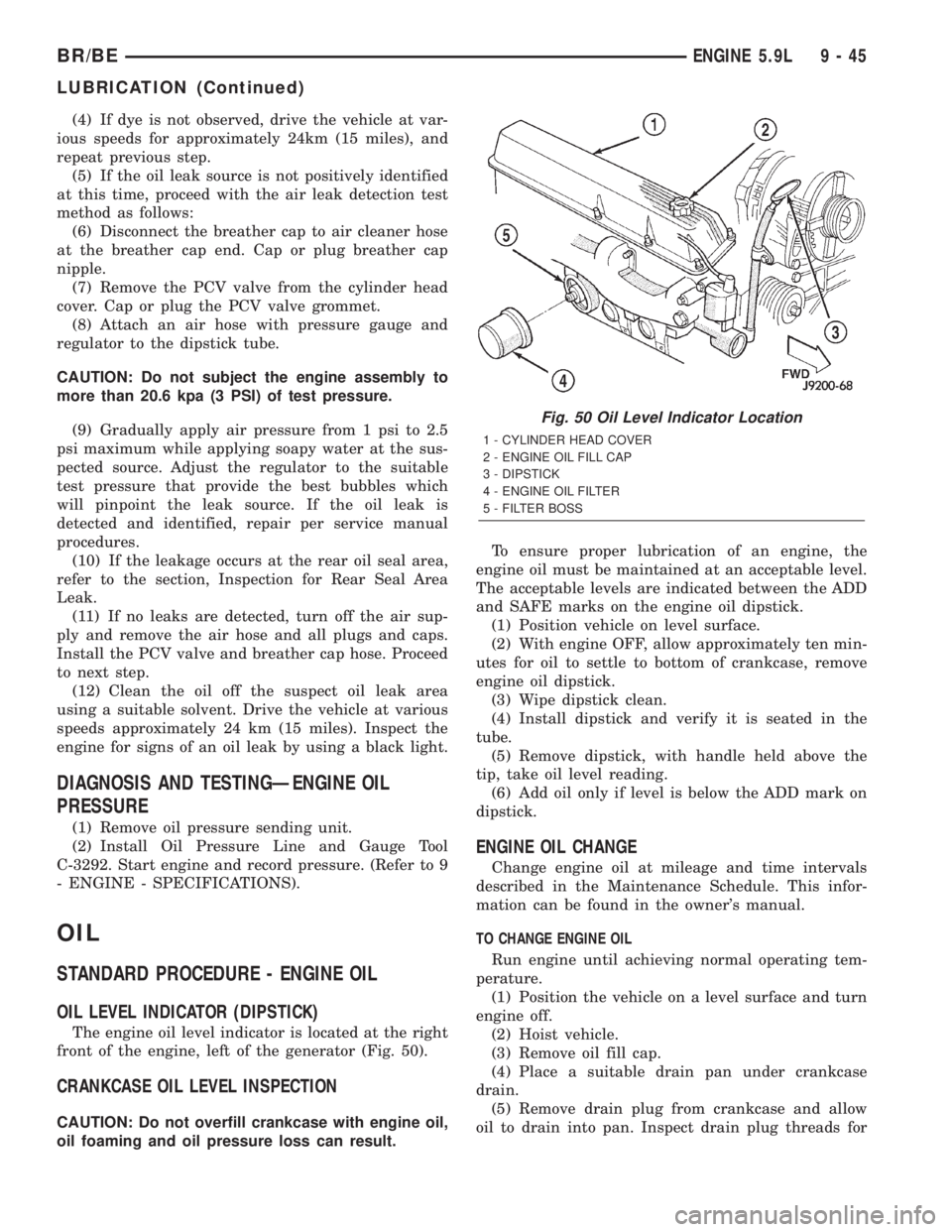
OIL LEVEL INDICATOR (DIPSTICK)
The engine oil level indicator is located at the right
front of the engine, left of the generator (Fig. 50).
CRANKCASE OIL LEVEL INSPECTION
CAUTION: Do not overfill crankcase with engine oil,
oil foaming and oil pressure loss can result.To ensure proper lubrication of an engine, the
engine oil must be maintained at an acceptable level.
The acceptable levels are indicated between the ADD
and SAFE marks on the engine oil dipstick.
(1) Position vehicle on level surface.
(2) With engine OFF, allow approximately ten min-
utes for oil to settle to bottom of crankcase, remove
engine oil dipstick.
(3) Wipe dipstick clean.
(4) Install dipstick and verify it is seated in the
tube.
(5) Remove dipstick, with handle held above the
tip, take oil level reading.
(6) Add oil only if level is below the ADD mark on
dipstick.
ENGINE OIL CHANGE
Change engine oil at mileage and time intervals
described in the Maintenance Schedule. This infor-
mation can be found in the owner's manual.
TO CHANGE ENGINE OIL
Run engine until achieving normal operating tem-
perature.
(1) Position the vehicle on a level surface and turn
engine off.
(2) Hoist vehicle.
(3) Remove oil fill cap.
(4) Place a suitable drain pan under crankcase
drain.
(5) Remove drain plug from crankcase and allow
oil to drain into pan. Inspect drain plug threads for
Fig. 50 Oil Level Indicator Location
1 - CYLINDER HEAD COVER
2 - ENGINE OIL FILL CAP
3 - DIPSTICK
4 - ENGINE OIL FILTER
5 - FILTER BOSS
BR/BEENGINE 5.9L 9 - 45
LUBRICATION (Continued)
Page 1121 of 2255
stretching or other damage. Replace drain plug and
gasket if damaged.
(6) Install drain plug in crankcase.
(7) Change oil filter (Refer to 9 - ENGINE/LUBRI-
CATION/OIL FILTER - REMOVAL).
(8) Lower vehicle and fill crankcase with specified
type (Refer to LUBRICATION & MAINTENANCE/
FLUID TYPES - DESCRIPTION) and amount of
engine oil (Refer to LUBRICATION & MAINTE-
NANCE - SPECIFICATIONS).
(9) Install oil fill cap.
(10) Start engine and inspect for leaks.
(11) Stop engine and inspect oil level.
OIL FILTER
REMOVAL
All engines are equipped with a high quality full-
flow, disposable type oil filter. DaimlerChrysler Cor-
poration recommends a Mopartor equivalent oil
filter be used.
(1) Position a drain pan under the oil filter.
(2) Using a suitable oil filter wrench loosen filter.
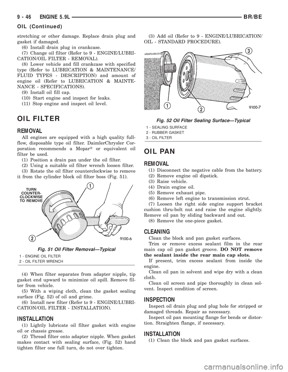
(3) Rotate the oil filter counterclockwise to remove
it from the cylinder block oil filter boss (Fig. 51).
(4) When filter separates from adapter nipple, tip
gasket end upward to minimize oil spill. Remove fil-
ter from vehicle.
(5) With a wiping cloth, clean the gasket sealing
surface (Fig. 52) of oil and grime.
(6) Install new filter (Refer to 9 - ENGINE/LUBRI-
CATION/OIL FILTER - INSTALLATION).
INSTALLATION
(1) Lightly lubricate oil filter gasket with engine
oil or chassis grease.
(2) Thread filter onto adapter nipple. When gasket
makes contact with sealing surface, (Fig. 52) hand
tighten filter one full turn, do not over tighten.(3) Add oil (Refer to 9 - ENGINE/LUBRICATION/
OIL - STANDARD PROCEDURE).
OIL PAN
REMOVAL
(1) Disconnect the negative cable from the battery.
(2) Remove engine oil dipstick.
(3) Raise vehicle.
(4) Drain engine oil.
(5) Remove exhaust pipe.
(6) Remove left engine to transmission strut.
(7) Loosen the right side engine support bracket
cushion thru-bolt nut and raise the engine slightly.
Remove oil pan by sliding backward and out.
(8) Remove the one-piece gasket.
CLEANING
Clean the block and pan gasket surfaces.
Trim or remove excess sealant film in the rear
main cap oil pan gasket groove.DO NOT remove
the sealant inside the rear main cap slots.
If present, trim excess sealant from inside the
engine.
Clean oil pan in solvent and wipe dry with a clean
cloth.
Clean oil screen and pipe thoroughly in clean sol-
vent. Inspect condition of screen.
INSPECTION
Inspect oil drain plug and plug hole for stripped or
damaged threads. Repair as necessary.
Inspect oil pan mounting flange for bends or distor-
tion. Straighten flange, if necessary.
INSTALLATION
(1) Clean the block and pan gasket surfaces.
Fig. 51 Oil Filter RemovalÐTypical
1 - ENGINE OIL FILTER
2 - OIL FILTER WRENCH
Fig. 52 Oil Filter Sealing SurfaceÐTypical
1 - SEALING SURFACE
2 - RUBBER GASKET
3 - OIL FILTER
9 - 46 ENGINE 5.9LBR/BE
OIL (Continued)
Page 1122 of 2255
(2) Trim or remove excess sealant film in the rear
main cap oil pan gasket groove.DO NOT remove
the sealant inside the rear main cap slots.
(3) If present, trim excess sealant from inside the
engine.
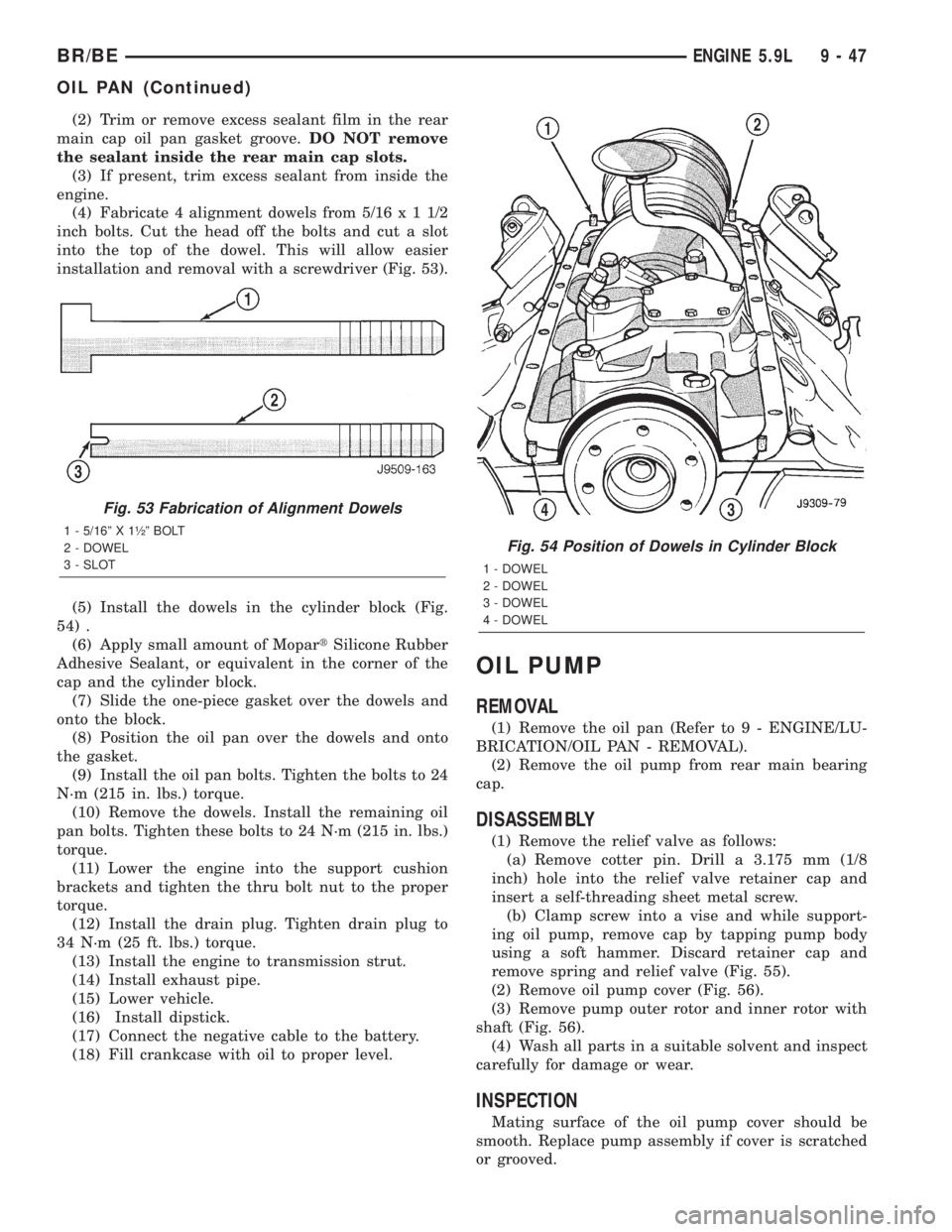
(4) Fabricate 4 alignment dowels from 5/16x11/2
inch bolts. Cut the head off the bolts and cut a slot
into the top of the dowel. This will allow easier
installation and removal with a screwdriver (Fig. 53).
(5) Install the dowels in the cylinder block (Fig.
54) .
(6) Apply small amount of MopartSilicone Rubber
Adhesive Sealant, or equivalent in the corner of the
cap and the cylinder block.
(7) Slide the one-piece gasket over the dowels and
onto the block.
(8) Position the oil pan over the dowels and onto
the gasket.
(9) Install the oil pan bolts. Tighten the bolts to 24
N´m (215 in. lbs.) torque.
(10) Remove the dowels. Install the remaining oil
pan bolts. Tighten these bolts to 24 N´m (215 in. lbs.)
torque.
(11) Lower the engine into the support cushion
brackets and tighten the thru bolt nut to the proper
torque.
(12) Install the drain plug. Tighten drain plug to
34 N´m (25 ft. lbs.) torque.
(13) Install the engine to transmission strut.
(14) Install exhaust pipe.
(15) Lower vehicle.
(16) Install dipstick.
(17) Connect the negative cable to the battery.
(18) Fill crankcase with oil to proper level.
OIL PUMP
REMOVAL
(1) Remove the oil pan (Refer to 9 - ENGINE/LU-
BRICATION/OIL PAN - REMOVAL).
(2) Remove the oil pump from rear main bearing
cap.
DISASSEMBLY
(1) Remove the relief valve as follows:
(a) Remove cotter pin. Drill a 3.175 mm (1/8
inch) hole into the relief valve retainer cap and
insert a self-threading sheet metal screw.
(b) Clamp screw into a vise and while support-
ing oil pump, remove cap by tapping pump body
using a soft hammer. Discard retainer cap and
remove spring and relief valve (Fig. 55).
(2) Remove oil pump cover (Fig. 56).
(3) Remove pump outer rotor and inner rotor with
shaft (Fig. 56).
(4) Wash all parts in a suitable solvent and inspect
carefully for damage or wear.
INSPECTION
Mating surface of the oil pump cover should be
smooth. Replace pump assembly if cover is scratched
or grooved.
Fig. 53 Fabrication of Alignment Dowels
1 - 5/16º X 1óº BOLT
2 - DOWEL
3 - SLOT
Fig. 54 Position of Dowels in Cylinder Block
1 - DOWEL
2 - DOWEL
3 - DOWEL
4 - DOWEL
BR/BEENGINE 5.9L 9 - 47
OIL PAN (Continued)
Page 1136 of 2255
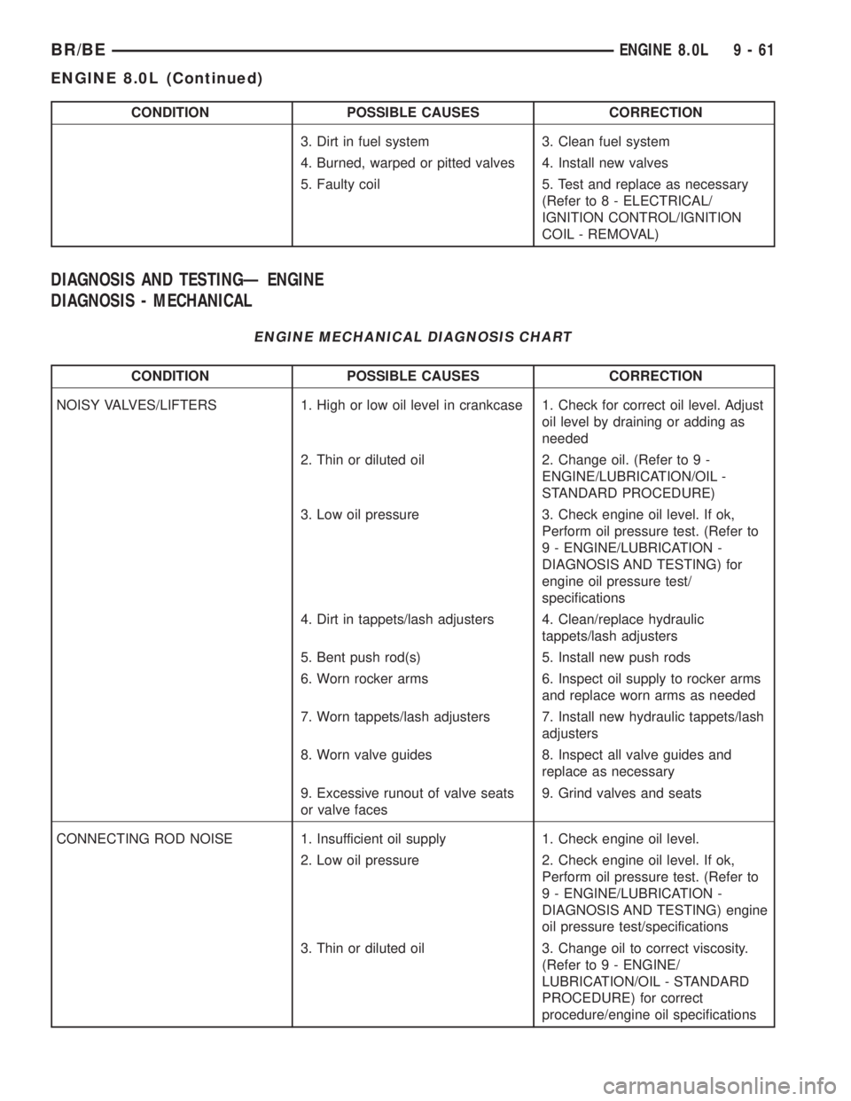
CONDITION POSSIBLE CAUSES CORRECTION
3. Dirt in fuel system 3. Clean fuel system
4. Burned, warped or pitted valves 4. Install new valves
5. Faulty coil 5. Test and replace as necessary
(Refer to 8 - ELECTRICAL/
IGNITION CONTROL/IGNITION
COIL - REMOVAL)
DIAGNOSIS AND TESTINGÐ ENGINE
DIAGNOSIS - MECHANICAL
ENGINE MECHANICAL DIAGNOSIS CHART
CONDITION POSSIBLE CAUSES CORRECTION
NOISY VALVES/LIFTERS 1. High or low oil level in crankcase 1. Check for correct oil level. Adjust
oil level by draining or adding as
needed
2. Thin or diluted oil 2. Change oil. (Refer to 9 -
ENGINE/LUBRICATION/OIL -
STANDARD PROCEDURE)
3. Low oil pressure 3. Check engine oil level. If ok,
Perform oil pressure test. (Refer to
9 - ENGINE/LUBRICATION -
DIAGNOSIS AND TESTING) for
engine oil pressure test/
specifications
4. Dirt in tappets/lash adjusters 4. Clean/replace hydraulic
tappets/lash adjusters
5. Bent push rod(s) 5. Install new push rods
6. Worn rocker arms 6. Inspect oil supply to rocker arms
and replace worn arms as needed
7. Worn tappets/lash adjusters 7. Install new hydraulic tappets/lash
adjusters
8. Worn valve guides 8. Inspect all valve guides and
replace as necessary
9. Excessive runout of valve seats
or valve faces9. Grind valves and seats
CONNECTING ROD NOISE 1. Insufficient oil supply 1. Check engine oil level.
2. Low oil pressure 2. Check engine oil level. If ok,
Perform oil pressure test. (Refer to
9 - ENGINE/LUBRICATION -
DIAGNOSIS AND TESTING) engine
oil pressure test/specifications
3. Thin or diluted oil 3. Change oil to correct viscosity.
(Refer to 9 - ENGINE/
LUBRICATION/OIL - STANDARD
PROCEDURE) for correct
procedure/engine oil specifications
BR/BEENGINE 8.0L 9 - 61
ENGINE 8.0L (Continued)
Page 1137 of 2255
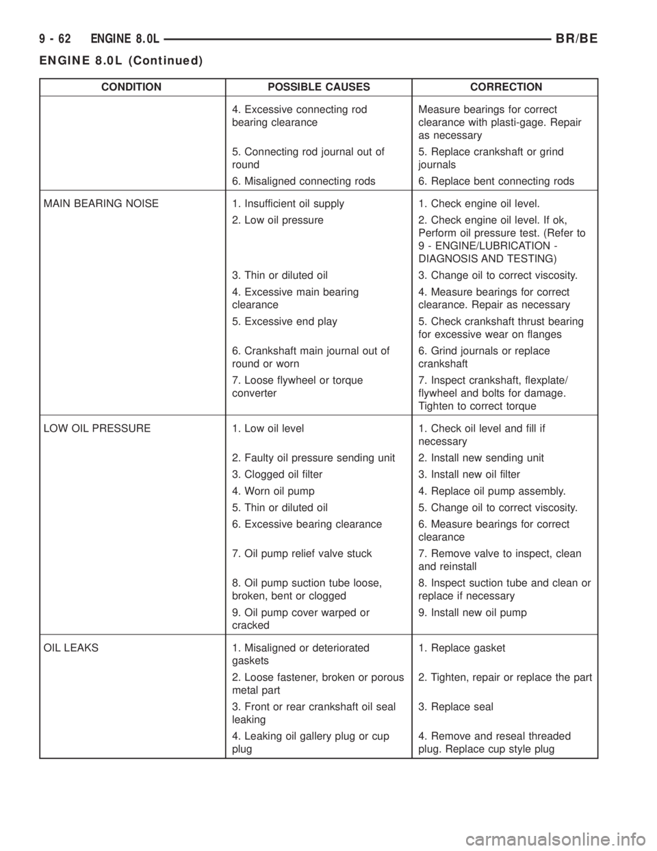
CONDITION POSSIBLE CAUSES CORRECTION
4. Excessive connecting rod
bearing clearanceMeasure bearings for correct
clearance with plasti-gage. Repair
as necessary
5. Connecting rod journal out of
round5. Replace crankshaft or grind
journals
6. Misaligned connecting rods 6. Replace bent connecting rods
MAIN BEARING NOISE 1. Insufficient oil supply 1. Check engine oil level.
2. Low oil pressure 2. Check engine oil level. If ok,
Perform oil pressure test. (Refer to
9 - ENGINE/LUBRICATION -
DIAGNOSIS AND TESTING)
3. Thin or diluted oil 3. Change oil to correct viscosity.
4. Excessive main bearing
clearance4. Measure bearings for correct
clearance. Repair as necessary
5. Excessive end play 5. Check crankshaft thrust bearing
for excessive wear on flanges
6. Crankshaft main journal out of
round or worn6. Grind journals or replace
crankshaft
7. Loose flywheel or torque
converter7. Inspect crankshaft, flexplate/
flywheel and bolts for damage.
Tighten to correct torque
LOW OIL PRESSURE 1. Low oil level 1. Check oil level and fill if
necessary
2. Faulty oil pressure sending unit 2. Install new sending unit
3. Clogged oil filter 3. Install new oil filter
4. Worn oil pump 4. Replace oil pump assembly.
5. Thin or diluted oil 5. Change oil to correct viscosity.
6. Excessive bearing clearance 6. Measure bearings for correct
clearance
7. Oil pump relief valve stuck 7. Remove valve to inspect, clean
and reinstall
8. Oil pump suction tube loose,
broken, bent or clogged8. Inspect suction tube and clean or
replace if necessary
9. Oil pump cover warped or
cracked9. Install new oil pump
OIL LEAKS 1. Misaligned or deteriorated
gaskets1. Replace gasket
2. Loose fastener, broken or porous
metal part2. Tighten, repair or replace the part
3. Front or rear crankshaft oil seal
leaking3. Replace seal
4. Leaking oil gallery plug or cup
plug4. Remove and reseal threaded
plug. Replace cup style plug
9 - 62 ENGINE 8.0LBR/BE
ENGINE 8.0L (Continued)
Page 1138 of 2255
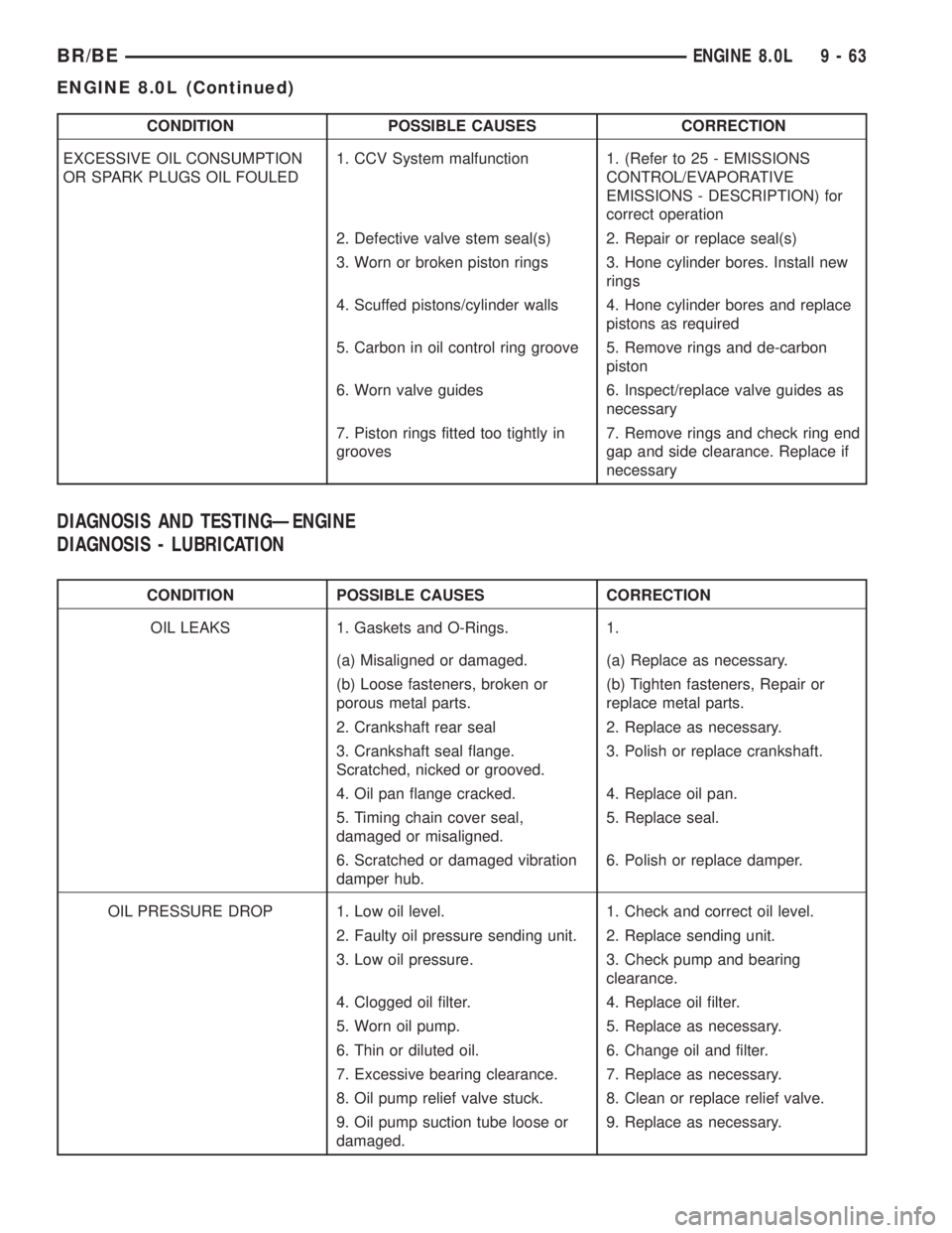
CONDITION POSSIBLE CAUSES CORRECTION
EXCESSIVE OIL CONSUMPTION
OR SPARK PLUGS OIL FOULED1. CCV System malfunction 1. (Refer to 25 - EMISSIONS
CONTROL/EVAPORATIVE
EMISSIONS - DESCRIPTION) for
correct operation
2. Defective valve stem seal(s) 2. Repair or replace seal(s)
3. Worn or broken piston rings 3. Hone cylinder bores. Install new
rings
4. Scuffed pistons/cylinder walls 4. Hone cylinder bores and replace
pistons as required
5. Carbon in oil control ring groove 5. Remove rings and de-carbon
piston
6. Worn valve guides 6. Inspect/replace valve guides as
necessary
7. Piston rings fitted too tightly in
grooves7. Remove rings and check ring end
gap and side clearance. Replace if
necessary
DIAGNOSIS AND TESTINGÐENGINE
DIAGNOSIS - LUBRICATION
CONDITION POSSIBLE CAUSES CORRECTION
OIL LEAKS 1. Gaskets and O-Rings. 1.
(a) Misaligned or damaged. (a) Replace as necessary.
(b) Loose fasteners, broken or
porous metal parts.(b) Tighten fasteners, Repair or
replace metal parts.
2. Crankshaft rear seal 2. Replace as necessary.
3. Crankshaft seal flange.
Scratched, nicked or grooved.3. Polish or replace crankshaft.
4. Oil pan flange cracked. 4. Replace oil pan.
5. Timing chain cover seal,
damaged or misaligned.5. Replace seal.
6. Scratched or damaged vibration
damper hub.6. Polish or replace damper.
OIL PRESSURE DROP 1. Low oil level. 1. Check and correct oil level.
2. Faulty oil pressure sending unit. 2. Replace sending unit.
3. Low oil pressure. 3. Check pump and bearing
clearance.
4. Clogged oil filter. 4. Replace oil filter.
5. Worn oil pump. 5. Replace as necessary.
6. Thin or diluted oil. 6. Change oil and filter.
7. Excessive bearing clearance. 7. Replace as necessary.
8. Oil pump relief valve stuck. 8. Clean or replace relief valve.
9. Oil pump suction tube loose or
damaged.9. Replace as necessary.
BR/BEENGINE 8.0L 9 - 63
ENGINE 8.0L (Continued)
Page 1139 of 2255
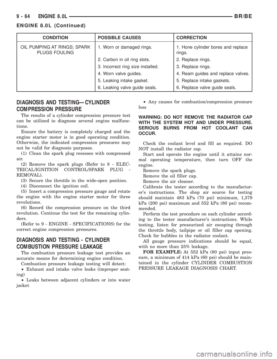
CONDITION POSSIBLE CAUSES CORRECTION
OIL PUMPING AT RINGS; SPARK
PLUGS FOULING1. Worn or damaged rings. 1. Hone cylinder bores and replace
rings.
2. Carbon in oil ring slots. 2. Replace rings.
3. Incorrect ring size installed. 3. Replace rings.
4. Worn valve guides. 4. Ream guides and replace valves.
5. Leaking intake gasket. 5. Replace intake gaskets.
6. Leaking valve guide seals. 6. Replace valve guide seals.
DIAGNOSIS AND TESTINGÐCYLINDER
COMPRESSION PRESSURE
The results of a cylinder compression pressure test
can be utilized to diagnose several engine malfunc-
tions.
Ensure the battery is completely charged and the
engine starter motor is in good operating condition.
Otherwise, the indicated compression pressures may
not be valid for diagnosis purposes.
(1) Clean the spark plug recesses with compressed
air.
(2) Remove the spark plugs (Refer to 8 - ELEC-
TRICAL/IGNITION CONTROL/SPARK PLUG -
REMOVAL).
(3) Secure the throttle in the wide-open position.
(4) Disconnect the ignition coil.
(5) Insert a compression pressure gauge and rotate
the engine with the engine starter motor for three
revolutions.
(6) Record the compression pressure on the third
revolution. Continue the test for the remaining cylin-
ders.
(Refer to 9 - ENGINE - SPECIFICATIONS) for the
correct engine compression pressures.
DIAGNOSIS AND TESTING - CYLINDER
COMBUSTION PRESSURE LEAKAGE
The combustion pressure leakage test provides an
accurate means for determining engine condition.
Combustion pressure leakage testing will detect:
²Exhaust and intake valve leaks (improper seat-
ing)
²Leaks between adjacent cylinders or into water
jacket²Any causes for combustion/compression pressure
loss
WARNING: DO NOT REMOVE THE RADIATOR CAP
WITH THE SYSTEM HOT AND UNDER PRESSURE.
SERIOUS BURNS FROM HOT COOLANT CAN
OCCUR.
Check the coolant level and fill as required. DO
NOT install the radiator cap.
Start and operate the engine until it attains nor-
mal operating temperature, then turn OFF the
engine.
Remove the spark plugs.
Remove the oil filler cap.
Remove the air cleaner.
Calibrate the tester according to the manufactur-
er's instructions. The shop air source for testing
should maintain 483 kPa (70 psi) minimum, 1,379
kPa (200 psi) maximum and 552 kPa (80 psi) recom-
mended.
Perform the test procedure on each cylinder accord-
ing to the tester manufacturer's instructions. While
testing, listen for pressurized air escaping through
the throttle body, tailpipe or oil filler cap opening.
Check for bubbles in the radiator coolant.
All gauge pressure indications should be equal,
with no more than 25% leakage.
FOR EXAMPLE:At 552 kPa (80 psi) input pres-
sure, a minimum of 414 kPa (60 psi) should be main-
tained in the cylinder CYLINDER COMBUSTION
PRESSURE LEAKAGE DIAGNOSIS CHART.
9 - 64 ENGINE 8.0LBR/BE
ENGINE 8.0L (Continued)