2002 DODGE RAM torque
[x] Cancel search: torquePage 1264 of 2255
(8) Install and tighten the gear housing bolts to 24
N´m (18 ft. lbs.) torque.
(9) Install and tighten the oil pan bolts to 24 N´m
(18 ft. lbs.) torque.
(10) Install the camshaft (Refer to 9 - ENGINE/
ENGINE BLOCK/CAMSHAFT & BEARINGS (IN
BLOCK) - INSTALLATION). Align the crankshaft,
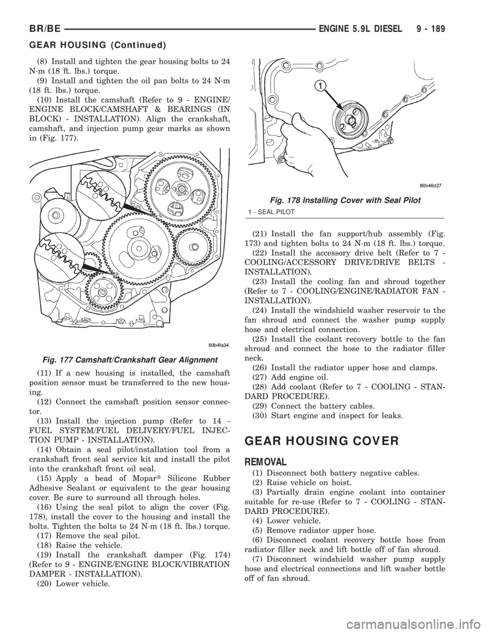
camshaft, and injection pump gear marks as shown
in (Fig. 177).
(11) If a new housing is installed, the camshaft
position sensor must be transferred to the new hous-
ing.
(12) Connect the camshaft position sensor connec-
tor.
(13) Install the injection pump (Refer to 14 -
FUEL SYSTEM/FUEL DELIVERY/FUEL INJEC-
TION PUMP - INSTALLATION).
(14) Obtain a seal pilot/installation tool from a
crankshaft front seal service kit and install the pilot
into the crankshaft front oil seal.
(15) Apply a bead of MopartSilicone Rubber
Adhesive Sealant or equivalent to the gear housing
cover. Be sure to surround all through holes.
(16) Using the seal pilot to align the cover (Fig.
178), install the cover to the housing and install the
bolts. Tighten the bolts to 24 N´m (18 ft. lbs.) torque.
(17) Remove the seal pilot.
(18) Raise the vehicle.
(19) Install the crankshaft damper (Fig. 174)
(Refer to 9 - ENGINE/ENGINE BLOCK/VIBRATION
DAMPER - INSTALLATION).
(20) Lower vehicle.(21) Install the fan support/hub assembly (Fig.
173) and tighten bolts to 24 N´m (18 ft. lbs.) torque.
(22) Install the accessory drive belt (Refer to 7 -
COOLING/ACCESSORY DRIVE/DRIVE BELTS -
INSTALLATION).
(23) Install the cooling fan and shroud together
(Refer to 7 - COOLING/ENGINE/RADIATOR FAN -
INSTALLATION).
(24) Install the windshield washer reservoir to the
fan shroud and connect the washer pump supply
hose and electrical connection.
(25) Install the coolant recovery bottle to the fan
shroud and connect the hose to the radiator filler
neck.
(26) Install the radiator upper hose and clamps.
(27) Add engine oil.
(28) Add coolant (Refer to 7 - COOLING - STAN-
DARD PROCEDURE).
(29) Connect the battery cables.
(30) Start engine and inspect for leaks.
GEAR HOUSING COVER
REMOVAL
(1) Disconnect both battery negative cables.
(2) Raise vehicle on hoist.
(3) Partially drain engine coolant into container
suitable for re-use (Refer to 7 - COOLING - STAN-
DARD PROCEDURE).
(4) Lower vehicle.
(5) Remove radiator upper hose.
(6) Disconnect coolant recovery bottle hose from
radiator filler neck and lift bottle off of fan shroud.
(7) Disconnect windshield washer pump supply
hose and electrical connections and lift washer bottle
off of fan shroud.
Fig. 177 Camshaft/Crankshaft Gear Alignment
Fig. 178 Installing Cover with Seal Pilot
1 - SEAL PILOT
BR/BEENGINE 5.9L DIESEL 9 - 189
GEAR HOUSING (Continued)
Page 1265 of 2255
(8) Remove viscous fan/drive assembly (Refer to 7 -
COOLING/ENGINE/RADIATOR FAN - REMOVAL).
(9) Remove the accessory drive belt (Refer to 7 -
COOLING/ACCESSORY DRIVE/DRIVE BELTS -
REMOVAL).
(10) Remove the cooling fan support/hub from the
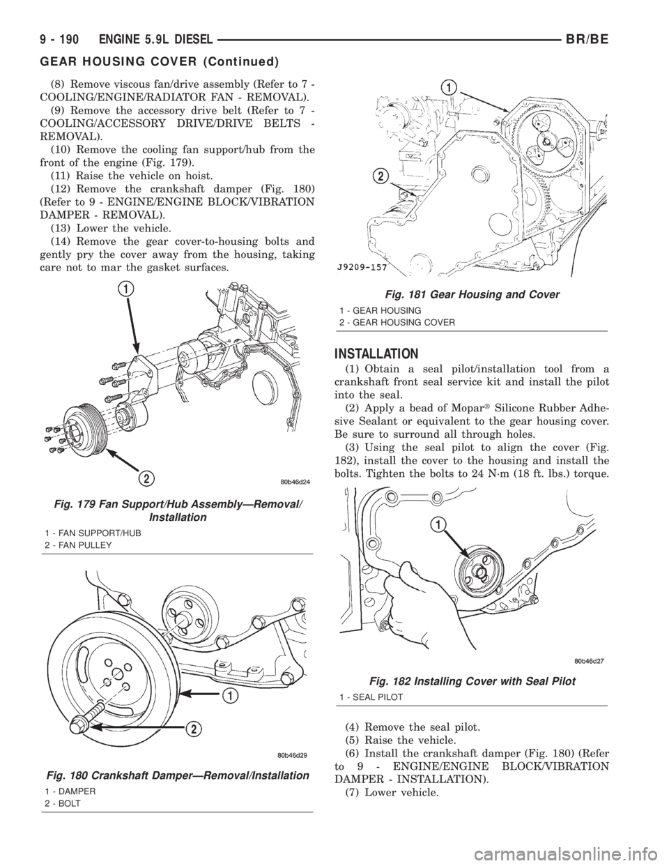
front of the engine (Fig. 179).
(11) Raise the vehicle on hoist.
(12) Remove the crankshaft damper (Fig. 180)
(Refer to 9 - ENGINE/ENGINE BLOCK/VIBRATION
DAMPER - REMOVAL).
(13) Lower the vehicle.
(14) Remove the gear cover-to-housing bolts and
gently pry the cover away from the housing, taking
care not to mar the gasket surfaces.
INSTALLATION
(1) Obtain a seal pilot/installation tool from a
crankshaft front seal service kit and install the pilot
into the seal.
(2) Apply a bead of MopartSilicone Rubber Adhe-
sive Sealant or equivalent to the gear housing cover.
Be sure to surround all through holes.
(3) Using the seal pilot to align the cover (Fig.
182), install the cover to the housing and install the
bolts. Tighten the bolts to 24 N´m (18 ft. lbs.) torque.
(4) Remove the seal pilot.
(5) Raise the vehicle.
(6) Install the crankshaft damper (Fig. 180) (Refer
to 9 - ENGINE/ENGINE BLOCK/VIBRATION
DAMPER - INSTALLATION).
(7) Lower vehicle.
Fig. 179 Fan Support/Hub AssemblyÐRemoval/
Installation
1 - FAN SUPPORT/HUB
2 - FAN PULLEY
Fig. 180 Crankshaft DamperÐRemoval/Installation
1 - DAMPER
2 - BOLT
Fig. 181 Gear Housing and Cover
1 - GEAR HOUSING
2 - GEAR HOUSING COVER
Fig. 182 Installing Cover with Seal Pilot
1 - SEAL PILOT
9 - 190 ENGINE 5.9L DIESELBR/BE
GEAR HOUSING COVER (Continued)
Page 1266 of 2255
(8) Install the fan support/hub assy. (Fig. 179) and
tighten bolts to 24 N´m (18 ft. lbs.) torque.
(9) Install the accessory drive belt (Refer to 7 -
COOLING/ACCESSORY DRIVE/DRIVE BELTS -
INSTALLATION).
(10) Install the cooling fan and shroud together
(Refer to 7 - COOLING/ENGINE/RADIATOR FAN -
INSTALLATION).
(11) Install the windshield washer reservoir to the
fan shroud and connect the washer pump supply
hose and electrical connection.(12) Install the coolant recovery bottle to the fan
shroud and connect the hose to the radiator filler
neck.
(13) Install the radiator upper hose and clamps.
(14) Add coolant (Refer to 7 - COOLING - STAN-
DARD PROCEDURE).
(15) Connect the battery cables.
(16) Start engine and inspect for leaks.
BR/BEENGINE 5.9L DIESEL 9 - 191
GEAR HOUSING COVER (Continued)
Page 1268 of 2255
EXHAUST SYSTEM
TABLE OF CONTENTS
page page
EXHAUST SYSTEM
DESCRIPTION
DESCRIPTION - 5.9/8.0L.................2
DESCRIPTIONÐ5.9L DIESEL.............3
DIAGNOSIS AND TESTING
DIAGNOSIS AND TESTING - GAS ENGINE . . . 4
DIAGNOSIS AND TESTING - DIESEL
ENGINE..............................4
SPECIFICATIONS
TORQUE.............................5
CATALYTIC CONVERTER - 3.9L/5.2L/5.9L
DESCRIPTION..........................5
OPERATION............................5
REMOVAL.............................5
INSPECTION...........................6
INSTALLATION..........................6
CATALYTIC CONVERTER - 5.9L HD/8.0L
DESCRIPTION..........................6
OPERATION............................6
REMOVAL.............................6
INSPECTION...........................6
INSTALLATION..........................7
EXHAUST PIPE - 3.9L/5.2L/5.9L
REMOVAL.............................7
INSPECTION...........................7
INSTALLATION..........................7
EXHAUST PIPE - 5.9L HD/8.0L
REMOVAL.............................7
INSPECTION...........................8
INSTALLATION..........................8
EXHAUST PIPE - 5.9L DIESEL
REMOVAL.............................9
INSPECTION...........................9
INSTALLATION..........................9
HEAT SHIELDS
DESCRIPTION.........................10
REMOVAL.............................10
INSTALLATION.........................10
MUFFLER - 3.9L/5.2L/5.9L/8.0L
REMOVAL.............................10INSTALLATION.........................10
MUFFLER - 5.9L DIESEL
REMOVAL.............................11
INSTALLATION.........................11
TAILPIPE - 3.9L/5.2L/5.9L
REMOVAL.............................11
INSPECTION..........................11
INSTALLATION.........................11
TAILPIPE - 5.9L HD/8.0L
REMOVAL.............................12
INSPECTION..........................12
INSTALLATION.........................12
TAILPIPE - 5.9L DIESEL
REMOVAL.............................12
INSPECTION..........................12
INSTALLATION.........................13
RESONATOR
REMOVAL.............................13
INSTALLATION.........................13
TURBOCHARGER SYSTEM
DIAGNOSIS AND TESTING -
TURBOCHARGER BOOST PRESSURE.....13
TURBOCHARGER
DESCRIPTION.........................14
OPERATION...........................14
REMOVAL.............................15
CLEANING............................16
INSPECTION..........................16
INSTALLATION.........................17
CHARGE AIR COOLER AND PLUMBING
DESCRIPTION.........................18
OPERATION...........................18
DIAGNOSIS AND TESTING - CHARGE AIR
COOLER SYSTEM - LEAKS..............18
REMOVAL.............................18
CLEANING............................19
INSPECTION..........................19
INSTALLATION.........................20
BR/BEEXHAUST SYSTEM 11 - 1
Page 1272 of 2255
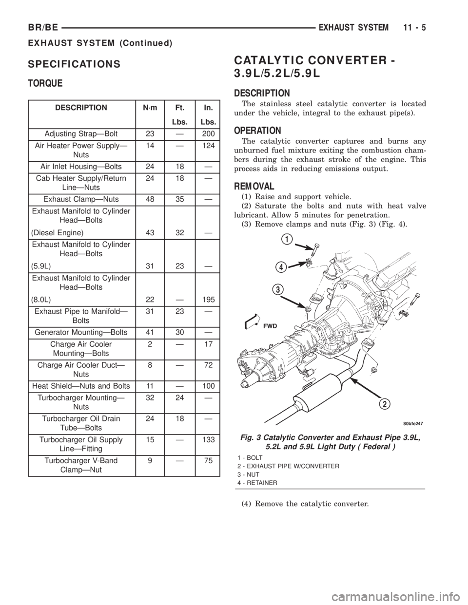
SPECIFICATIONS
TORQUE
DESCRIPTION N´m Ft. In.
Lbs. Lbs.
Adjusting StrapÐBolt 23 Ð 200
Air Heater Power SupplyÐ
Nuts14 Ð 124
Air Inlet HousingÐBolts 24 18 Ð
Cab Heater Supply/Return
LineÐNuts24 18 Ð
Exhaust ClampÐNuts 48 35 Ð
Exhaust Manifold to Cylinder
HeadÐBolts
(Diesel Engine) 43 32 Ð
Exhaust Manifold to Cylinder
HeadÐBolts
(5.9L) 31 23 Ð
Exhaust Manifold to Cylinder
HeadÐBolts
(8.0L) 22 Ð 195
Exhaust Pipe to ManifoldÐ
Bolts31 23 Ð
Generator MountingÐBolts 41 30 Ð
Charge Air Cooler
MountingÐBolts2Ð17
Charge Air Cooler DuctÐ
Nuts8Ð72
Heat ShieldÐNuts and Bolts 11 Ð 100
Turbocharger MountingÐ
Nuts32 24 Ð
Turbocharger Oil Drain
TubeÐBolts24 18 Ð
Turbocharger Oil Supply
LineÐFitting15 Ð 133
Turbocharger V-Band
ClampÐNut9Ð75
CATALYTIC CONVERTER -
3.9L/5.2L/5.9L
DESCRIPTION
The stainless steel catalytic converter is located
under the vehicle, integral to the exhaust pipe(s).
OPERATION
The catalytic converter captures and burns any
unburned fuel mixture exiting the combustion cham-
bers during the exhaust stroke of the engine. This
process aids in reducing emissions output.
REMOVAL
(1) Raise and support vehicle.
(2) Saturate the bolts and nuts with heat valve
lubricant. Allow 5 minutes for penetration.
(3) Remove clamps and nuts (Fig. 3) (Fig. 4).
(4) Remove the catalytic converter.
Fig. 3 Catalytic Converter and Exhaust Pipe 3.9L,
5.2L and 5.9L Light Duty ( Federal )
1 - BOLT
2 - EXHAUST PIPE W/CONVERTER
3 - NUT
4 - RETAINER
BR/BEEXHAUST SYSTEM 11 - 5
EXHAUST SYSTEM (Continued)
Page 1273 of 2255
INSPECTION
Look at the stainless steel body of the converter,
inspect for bulging or other distortion that could be a
result of overheating. If the converter has a heat
shield attached make sure it is not bent or loose.
If you suspect internal damage to the catalyst, tap-
ping the bottom of the catalyst with a rubber mallet
may indicate a damaged core.
INSTALLATION
(1) Assemble converter and clamps loosely in
place.
(2) Install the exhaust pipe onto exhaust mani-
folds, tighten 31 N´m (23 ft. lbs.).
(3) Tighten all clamp nuts to 48 N´m (35 ft. lbs.)
torque.
(4) Lower the vehicle.
(5) Start the engine and inspect for exhaust leaks
and exhaust system contact with the body panels. A
minimum of 25.4 mm (1.0 in.) is required between
exhaust system components and body/frame parts.
Adjust the alignment, if needed.
CATALYTIC CONVERTER - 5.9L
HD/8.0L
DESCRIPTION
The stainless steel catalytic converter is located
under the vehicle, attached to the exhaust pipe(s).
OPERATION
The catalytic converter captures and burns any
unburned fuel mixture exiting the combustion cham-
bers during the exhaust stroke of the engine. This
process aids in reducing emissions output.
REMOVAL
(1) Raise and support vehicle.
(2) Saturate the bolts and nuts with heat valve
lubricant. Allow 5 minutes for penetration.
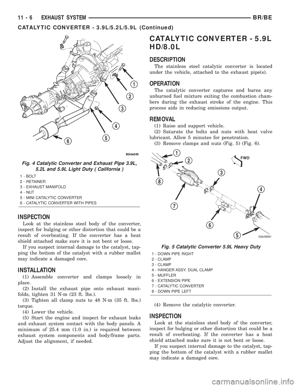
(3) Remove clamps and nuts (Fig. 5) (Fig. 6).
(4) Remove the catalytic converter.
INSPECTION
Look at the stainless steel body of the converter,
inspect for bulging or other distortion that could be a
result of overheating. If the converter has a heat
shield attached make sure it is not bent or loose.
If you suspect internal damage to the catalyst, tap-
ping the bottom of the catalyst with a rubber mallet
may indicate a damaged core.
Fig. 4 Catalytic Converter and Exhaust Pipe 3.9L,
5.2L and 5.9L Light Duty ( California )
1 - BOLT
2 - RETAINER
3 - EXHAUST MANIFOLD
4 - NUT
5 - MINI CATALYTIC CONVERTER
6 - CATALYTIC CONVERTER WITH PIPES
Fig. 5 Catalytic Converter 5.9L Heavy Duty
1 - DOWN PIPE RIGHT
2 - CLAMP
3 - CLAMP
4 - HANGER ASSY. DUAL CLAMP
5 - MUFFLER
6 - EXTENSION PIPE
7 - CATALYTIC CONVERTER
8 - DOWN PIPE LEFT
11 - 6 EXHAUST SYSTEMBR/BE
CATALYTIC CONVERTER - 3.9L/5.2L/5.9L (Continued)
Page 1274 of 2255

INSTALLATION
(1) Assemble converter and clamps loosely in
place.
(2) Tighten all clamp nuts to 48 N´m (35 ft. lbs.)
torque.
(3) Lower the vehicle.
(4) Start the engine and inspect for exhaust leaks
and exhaust system contact with the body panels. A
minimum of 25.4 mm (1.0 in.) is required between
exhaust system components and body/frame parts.
Adjust the alignment, if needed.
EXHAUST PIPE - 3.9L/5.2L/
5.9L
REMOVAL
(1) Raise and support the vehicle.
(2) Saturate the bolts and nuts with heat valve
lubricant. Allow 5 minutes for penetration.
(3) Remove exhaust pipe to manifold bolts, retain-
ers and nuts (Fig. 7).
(4) Remove the clamp nuts (Fig. 7).
(5) Remove the exhaust pipe.
INSPECTION
Discard rusted clamps, broken or worn supports
and attaching parts. Replace a component with orig-
inal equipment parts, or equivalent. This will assure
proper alignment with other parts in the system and
provide acceptable exhaust noise levels.
INSTALLATION
(1) Position the exhaust pipe for proper clearance
with the frame and underbody parts. A minimum
clearance of 25.4 mm (1.0 in.) is required.
(2) Position the exhaust pipe to manifold. Install
the bolts, retainers and nuts. Tighten the nuts to 31
N´m (23 ft. lbs.) torque.
(3) Tighten the clamp nuts to 48 N´m (35 ft. lbs.)
torque.
(4) Lower the vehicle.
(5) Start the engine and inspect for exhaust leaks
and exhaust system contact with the body panels.
Adjust the alignment, if needed.
EXHAUST PIPE - 5.9L HD/8.0L
REMOVAL
(1) Raise and support the vehicle.
(2) Saturate the bolts and nuts with heat valve
lubricant. Allow 5 minutes for penetration.
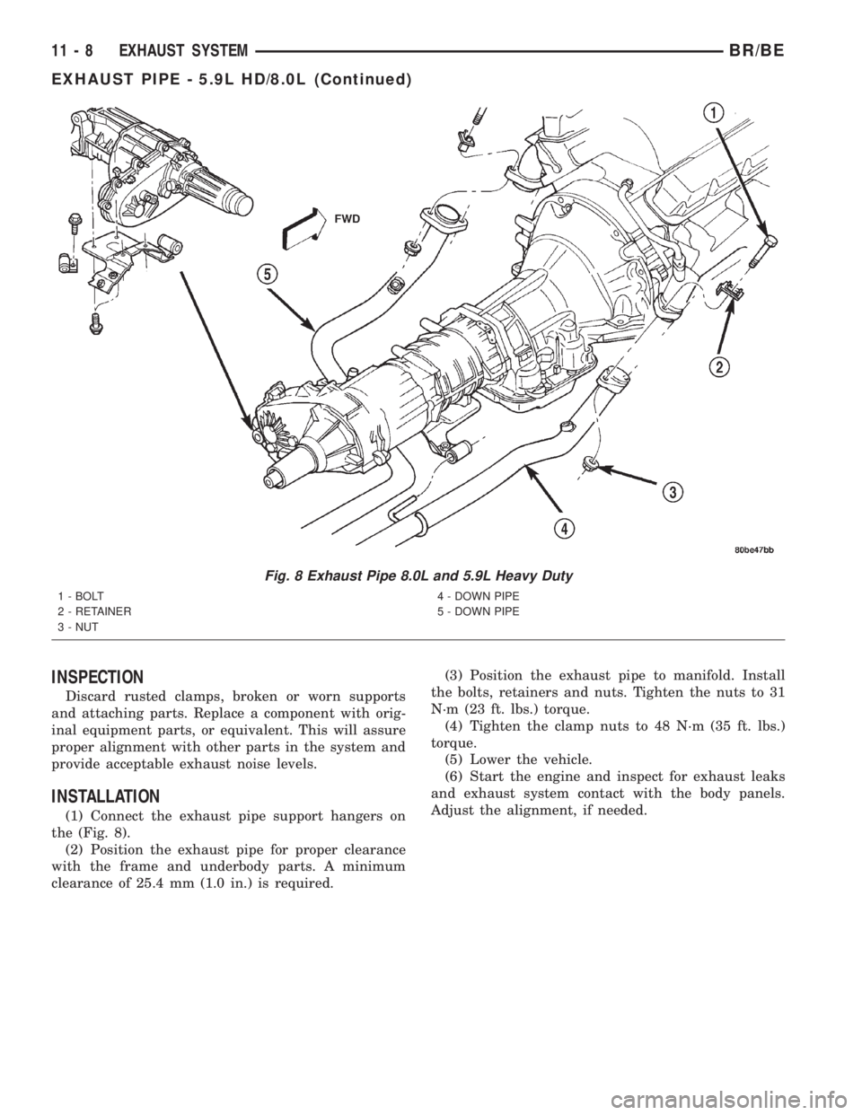
(3) Remove exhaust pipe to manifold bolts, retain-
ers and nuts (Fig. 8).
(4) Remove the clamp nuts (Fig. 9) (Fig. 10).
(5) Disconnect the exhaust pipe from the support
hangers on the 5.9L (Heavy Duty) and the 8.0L
engines (Fig. 8).
(6) Remove the exhaust pipe.
Fig. 6 Catalytic Converter 8.0L
1 - CLAMPS
2 - CATALYTIC CONVERTERS
3 - MUFFLER
4 - HANGER ASSY. DUAL CLAMP
5 - EXTENSION PIPES
6 - DOWN PIPEFig. 7 Exhaust Pipe 3.9L,5.2L, 5.9L Light Duty
1 - EXHAUST PIPE WITH CATALYTIC CONVERTER
2 - CLAMP
3 - MUFFLER
BR/BEEXHAUST SYSTEM 11 - 7
CATALYTIC CONVERTER - 5.9L HD/8.0L (Continued)
Page 1275 of 2255
INSPECTION
Discard rusted clamps, broken or worn supports
and attaching parts. Replace a component with orig-
inal equipment parts, or equivalent. This will assure
proper alignment with other parts in the system and
provide acceptable exhaust noise levels.
INSTALLATION
(1) Connect the exhaust pipe support hangers on
the (Fig. 8).
(2) Position the exhaust pipe for proper clearance
with the frame and underbody parts. A minimum
clearance of 25.4 mm (1.0 in.) is required.(3) Position the exhaust pipe to manifold. Install
the bolts, retainers and nuts. Tighten the nuts to 31
N´m (23 ft. lbs.) torque.
(4) Tighten the clamp nuts to 48 N´m (35 ft. lbs.)
torque.
(5) Lower the vehicle.
(6) Start the engine and inspect for exhaust leaks
and exhaust system contact with the body panels.
Adjust the alignment, if needed.
Fig. 8 Exhaust Pipe 8.0L and 5.9L Heavy Duty
1 - BOLT
2 - RETAINER
3 - NUT4 - DOWN PIPE
5 - DOWN PIPE
11 - 8 EXHAUST SYSTEMBR/BE
EXHAUST PIPE - 5.9L HD/8.0L (Continued)