2002 DODGE RAM torque
[x] Cancel search: torquePage 1236 of 2255
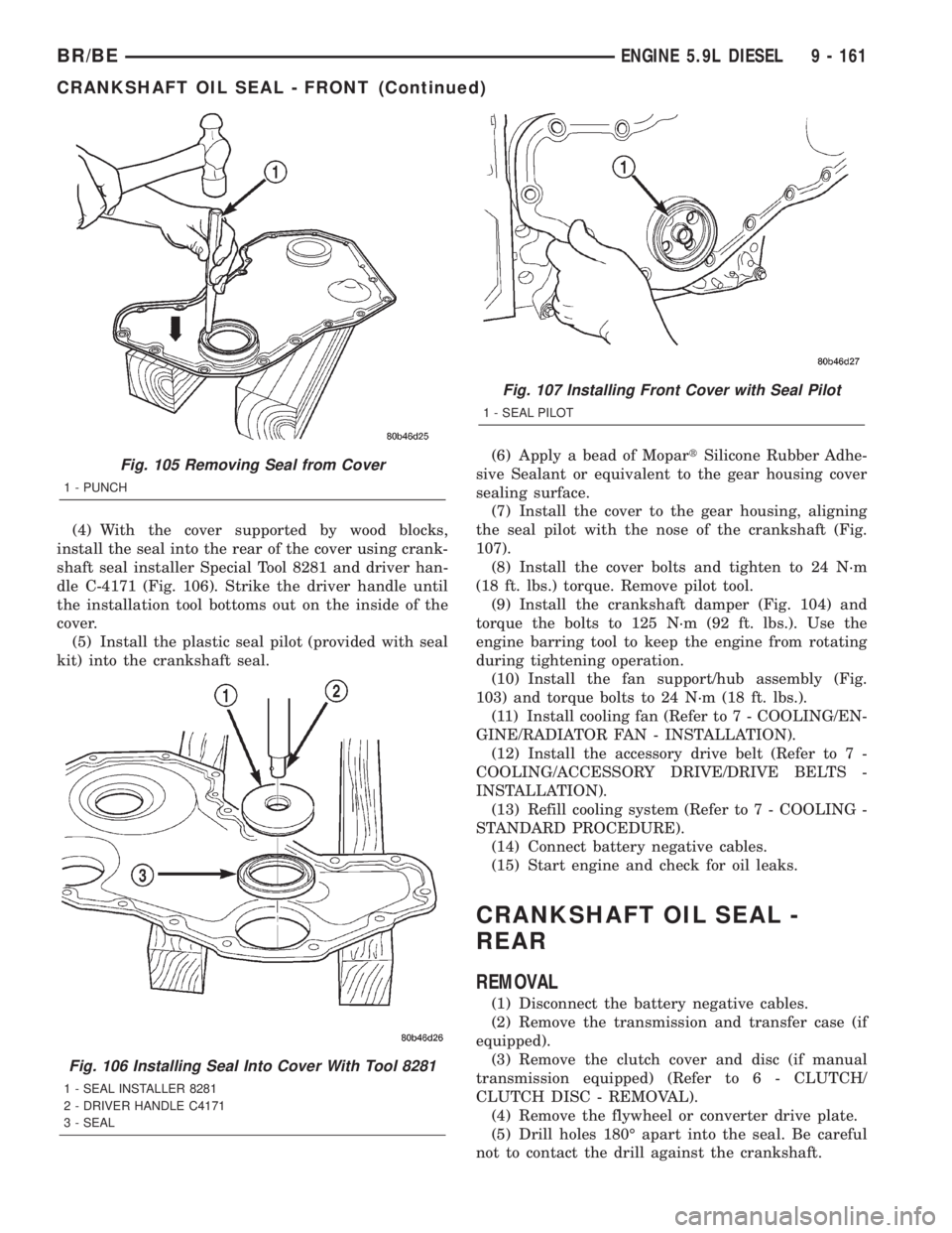
(4) With the cover supported by wood blocks,
install the seal into the rear of the cover using crank-
shaft seal installer Special Tool 8281 and driver han-
dle C-4171 (Fig. 106). Strike the driver handle until
the installation tool bottoms out on the inside of the
cover.
(5) Install the plastic seal pilot (provided with seal
kit) into the crankshaft seal.(6) Apply a bead of MopartSilicone Rubber Adhe-
sive Sealant or equivalent to the gear housing cover
sealing surface.
(7) Install the cover to the gear housing, aligning
the seal pilot with the nose of the crankshaft (Fig.
107).
(8) Install the cover bolts and tighten to 24 N´m
(18 ft. lbs.) torque. Remove pilot tool.
(9) Install the crankshaft damper (Fig. 104) and
torque the bolts to 125 N´m (92 ft. lbs.). Use the
engine barring tool to keep the engine from rotating
during tightening operation.
(10) Install the fan support/hub assembly (Fig.
103) and torque bolts to 24 N´m (18 ft. lbs.).
(11) Install cooling fan (Refer to 7 - COOLING/EN-
GINE/RADIATOR FAN - INSTALLATION).
(12) Install the accessory drive belt (Refer to 7 -
COOLING/ACCESSORY DRIVE/DRIVE BELTS -
INSTALLATION).
(13) Refill cooling system (Refer to 7 - COOLING -
STANDARD PROCEDURE).
(14) Connect battery negative cables.
(15) Start engine and check for oil leaks.
CRANKSHAFT OIL SEAL -
REAR
REMOVAL
(1) Disconnect the battery negative cables.
(2) Remove the transmission and transfer case (if
equipped).
(3) Remove the clutch cover and disc (if manual
transmission equipped) (Refer to 6 - CLUTCH/
CLUTCH DISC - REMOVAL).
(4) Remove the flywheel or converter drive plate.
(5) Drill holes 180É apart into the seal. Be careful
not to contact the drill against the crankshaft.
Fig. 105 Removing Seal from Cover
1 - PUNCH
Fig. 106 Installing Seal Into Cover With Tool 8281
1 - SEAL INSTALLER 8281
2 - DRIVER HANDLE C4171
3 - SEAL
Fig. 107 Installing Front Cover with Seal Pilot
1 - SEAL PILOT
BR/BEENGINE 5.9L DIESEL 9 - 161
CRANKSHAFT OIL SEAL - FRONT (Continued)
Page 1237 of 2255
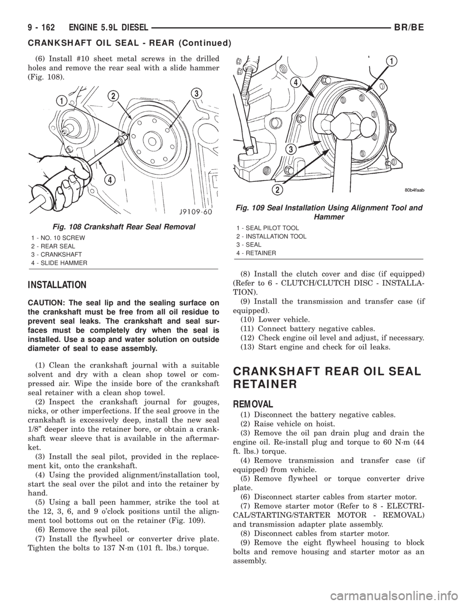
(6) Install #10 sheet metal screws in the drilled
holes and remove the rear seal with a slide hammer
(Fig. 108).
INSTALLATION
CAUTION: The seal lip and the sealing surface on
the crankshaft must be free from all oil residue to
prevent seal leaks. The crankshaft and seal sur-
faces must be completely dry when the seal is
installed. Use a soap and water solution on outside
diameter of seal to ease assembly.
(1) Clean the crankshaft journal with a suitable
solvent and dry with a clean shop towel or com-
pressed air. Wipe the inside bore of the crankshaft
seal retainer with a clean shop towel.
(2) Inspect the crankshaft journal for gouges,
nicks, or other imperfections. If the seal groove in the
crankshaft is excessively deep, install the new seal
1/8º deeper into the retainer bore, or obtain a crank-
shaft wear sleeve that is available in the aftermar-
ket.
(3) Install the seal pilot, provided in the replace-
ment kit, onto the crankshaft.
(4) Using the provided alignment/installation tool,
start the seal over the pilot and into the retainer by
hand.
(5) Using a ball peen hammer, strike the tool at
the 12, 3, 6, and 9 o'clock positions until the align-
ment tool bottoms out on the retainer (Fig. 109).
(6) Remove the seal pilot.
(7) Install the flywheel or converter drive plate.
Tighten the bolts to 137 N´m (101 ft. lbs.) torque.(8) Install the clutch cover and disc (if equipped)
(Refer to 6 - CLUTCH/CLUTCH DISC - INSTALLA-
TION).
(9) Install the transmission and transfer case (if
equipped).
(10) Lower vehicle.
(11) Connect battery negative cables.
(12) Check engine oil level and adjust, if necessary.
(13) Start engine and check for oil leaks.
CRANKSHAFT REAR OIL SEAL
RETAINER
REMOVAL
(1) Disconnect the battery negative cables.
(2) Raise vehicle on hoist.
(3) Remove the oil pan drain plug and drain the
engine oil. Re-install plug and torque to 60 N´m (44
ft. lbs.) torque.
(4) Remove transmission and transfer case (if
equipped) from vehicle.
(5) Remove flywheel or torque converter drive
plate.
(6) Disconnect starter cables from starter motor.
(7) Remove starter motor (Refer to 8 - ELECTRI-
CAL/STARTING/STARTER MOTOR - REMOVAL)
and transmission adapter plate assembly.
(8) Disconnect cables from starter motor.
(9) Remove the eight flywheel housing to block
bolts and remove housing and starter motor as an
assembly.
Fig. 108 Crankshaft Rear Seal Removal
1 - NO. 10 SCREW
2 - REAR SEAL
3 - CRANKSHAFT
4 - SLIDE HAMMER
Fig. 109 Seal Installation Using Alignment Tool and
Hammer
1 - SEAL PILOT TOOL
2 - INSTALLATION TOOL
3 - SEAL
4 - RETAINER
9 - 162 ENGINE 5.9L DIESELBR/BE
CRANKSHAFT OIL SEAL - REAR (Continued)
Page 1239 of 2255
(8) Install the oil pan, suction tube and gaskets
(Refer to 9 - ENGINE/LUBRICATION/OIL PAN -
INSTALLATION).
(9) Install the flywheel housing and bolts. Tighten
the bolts to 60 N´m (44 ft. lbs.) torque.
(10) Install the starter motor (Refer to 8 - ELEC-
TRICAL/STARTING/STARTER MOTOR - INSTAL-
LATION).
(11) Install the flywheel or converter drive plate.
Tighten bolts to 137 N´m (101 ft. lbs.)
(12) Install the transmission and transfer case (if
equipped).
(13) Lower vehicle.(14) Fill the crankcase with new engine oil.
(15) Connect the battery negative cables.
(16) Start engine and check for oil leaks.
SOLID LIFTERS/TAPPETS
REMOVAL
NOTE: This procedure requires use of Miller Tool
8502 Tappet Replacement Kit, or Cummins Tool Kit
#3822513.
(1) Remove camshaft (Refer to 9 - ENGINE/EN-
GINE BLOCK/CAMSHAFT & BEARINGS (IN
BLOCK) - REMOVAL).
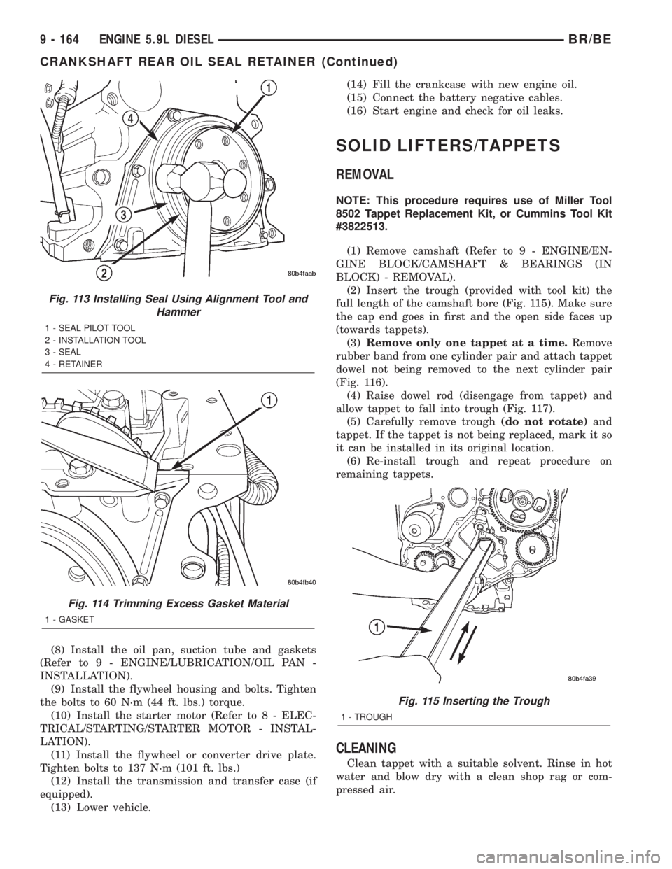
(2) Insert the trough (provided with tool kit) the
full length of the camshaft bore (Fig. 115). Make sure
the cap end goes in first and the open side faces up
(towards tappets).
(3)Remove only one tappet at a time.Remove
rubber band from one cylinder pair and attach tappet
dowel not being removed to the next cylinder pair
(Fig. 116).
(4) Raise dowel rod (disengage from tappet) and
allow tappet to fall into trough (Fig. 117).
(5) Carefully remove trough(do not rotate)and
tappet. If the tappet is not being replaced, mark it so
it can be installed in its original location.
(6) Re-install trough and repeat procedure on
remaining tappets.
CLEANING
Clean tappet with a suitable solvent. Rinse in hot
water and blow dry with a clean shop rag or com-
pressed air.
Fig. 113 Installing Seal Using Alignment Tool and
Hammer
1 - SEAL PILOT TOOL
2 - INSTALLATION TOOL
3 - SEAL
4 - RETAINER
Fig. 114 Trimming Excess Gasket Material
1 - GASKET
Fig. 115 Inserting the Trough
1 - TROUGH
9 - 164 ENGINE 5.9L DIESELBR/BE
CRANKSHAFT REAR OIL SEAL RETAINER (Continued)
Page 1242 of 2255
(1) Install any of the original connecting rod and
piston assemblies into the No.1 cylinder. DO NOT
install the piston rings.
(2) Install the upper bearing shell in the connect-
ing rod with the tang of the bearing in the slot of the
connecting rod. The connecting rod bearing shell
must be installed in the original connecting rod and
cap. Use clean lubricating oil to coat the inside diam-
eter of the connecting rod bearing shell.
(3) Install the bearing shell in the connecting rod
cap with the tang of the bearing in the slot to the
cap. Use clean lubricating oil to coat the inside diam-
eter of the bearing shell.
(4) The four digit number stamped on the connect-
ing rod and cap at the parting line must match andbe installed on the oil cooler side of the engine.
Install the connecting rod cap and cap screws.
Tighten the cap screws to 35 N´m (26 ft. lbs.) torque.
(5) Use a fine grit stone to remove any burrs from
the cylinder block head deck. Zero the dial indicator
to the cylinder block head deck.
(6) Move the dial indicator directly over the piston
pin to eliminate any side-to-side movement.
(7) Rotate the crankshaft to top dead center
(TDC). Rotate the crankshaft clockwise and counter-
clockwise to find the highest dial indicator reading.
Record the reading.
(8) Remove the piston and connecting rod assem-
bly from the No.1 cylinder and install the assembly
into the No.2 cylinder. Repeat the procedure for every
cylinder using the same piston and connecting rod
assembly.
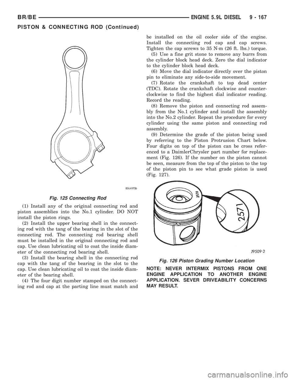
(9) Determine the grade of the piston being used
by referring to the Piston Protrusion Chart below.
Four digits on top of the piston can be cross refer-
enced to a DaimlerChrysler part number for replace-
ment (Fig. 126). If the number on the piston cannot
be seen, measure from the top of the piston to the top
of the piston pin to see what grade piston is used
(Fig. 127).
NOTE: NEVER INTERMIX PISTONS FROM ONE
ENGINE APPLICATION TO ANOTHER ENGINE
APPLICATION. SEVER DRIVEABILITY CONCERNS
MAY RESULT.
Fig. 125 Connecting Rod
Fig. 126 Piston Grading Number Location
BR/BEENGINE 5.9L DIESEL 9 - 167
PISTON & CONNECTING ROD (Continued)
Page 1246 of 2255
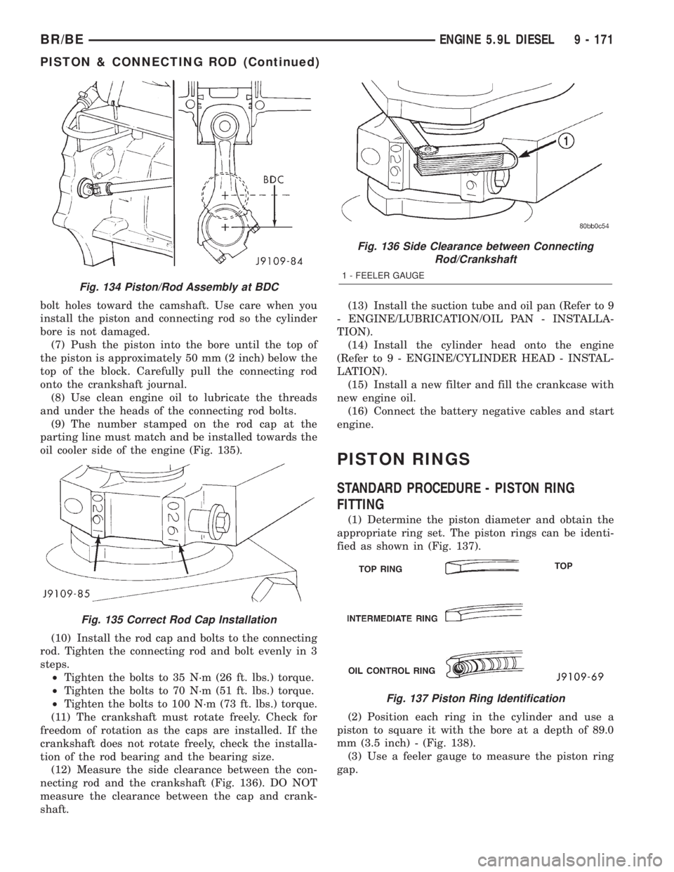
bolt holes toward the camshaft. Use care when you
install the piston and connecting rod so the cylinder
bore is not damaged.
(7) Push the piston into the bore until the top of
the piston is approximately 50 mm (2 inch) below the
top of the block. Carefully pull the connecting rod
onto the crankshaft journal.
(8) Use clean engine oil to lubricate the threads
and under the heads of the connecting rod bolts.
(9) The number stamped on the rod cap at the
parting line must match and be installed towards the
oil cooler side of the engine (Fig. 135).
(10) Install the rod cap and bolts to the connecting
rod. Tighten the connecting rod and bolt evenly in 3
steps.
²Tighten the bolts to 35 N´m (26 ft. lbs.) torque.
²Tighten the bolts to 70 N´m (51 ft. lbs.) torque.
²Tighten the bolts to 100 N´m (73 ft. lbs.) torque.
(11) The crankshaft must rotate freely. Check for
freedom of rotation as the caps are installed. If the
crankshaft does not rotate freely, check the installa-
tion of the rod bearing and the bearing size.
(12) Measure the side clearance between the con-
necting rod and the crankshaft (Fig. 136). DO NOT
measure the clearance between the cap and crank-
shaft.(13) Install the suction tube and oil pan (Refer to 9
- ENGINE/LUBRICATION/OIL PAN - INSTALLA-
TION).
(14) Install the cylinder head onto the engine
(Refer to 9 - ENGINE/CYLINDER HEAD - INSTAL-
LATION).
(15) Install a new filter and fill the crankcase with
new engine oil.
(16) Connect the battery negative cables and start
engine.
PISTON RINGS
STANDARD PROCEDURE - PISTON RING
FITTING
(1) Determine the piston diameter and obtain the
appropriate ring set. The piston rings can be identi-
fied as shown in (Fig. 137).
(2) Position each ring in the cylinder and use a
piston to square it with the bore at a depth of 89.0
mm (3.5 inch) - (Fig. 138).
(3) Use a feeler gauge to measure the piston ring
gap.
Fig. 134 Piston/Rod Assembly at BDC
Fig. 135 Correct Rod Cap Installation
Fig. 136 Side Clearance between Connecting
Rod/Crankshaft
1 - FEELER GAUGE
Fig. 137 Piston Ring Identification
BR/BEENGINE 5.9L DIESEL 9 - 171
PISTON & CONNECTING ROD (Continued)
Page 1248 of 2255
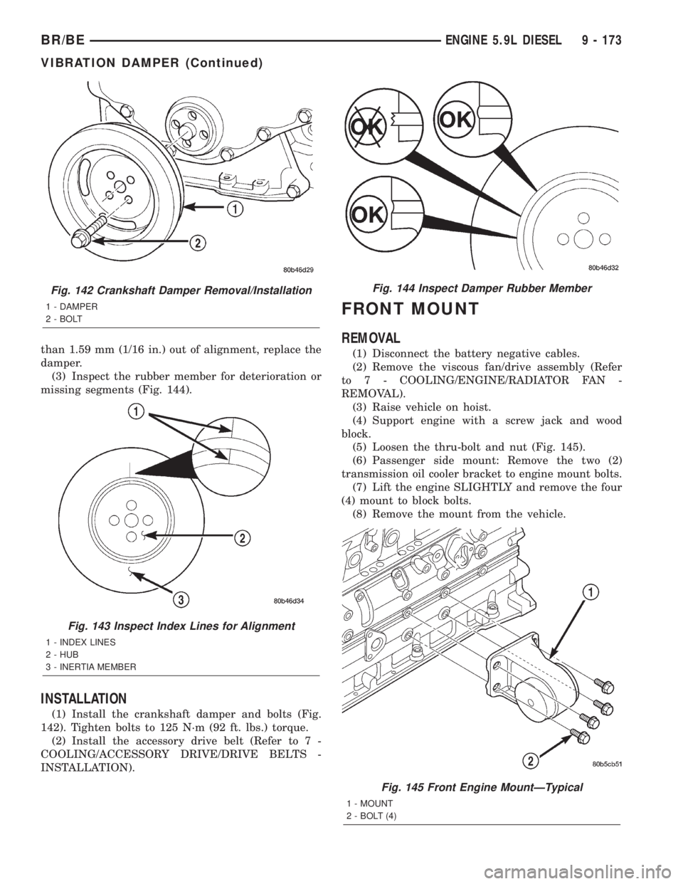
than 1.59 mm (1/16 in.) out of alignment, replace the
damper.
(3) Inspect the rubber member for deterioration or
missing segments (Fig. 144).
INSTALLATION
(1) Install the crankshaft damper and bolts (Fig.
142). Tighten bolts to 125 N´m (92 ft. lbs.) torque.
(2) Install the accessory drive belt (Refer to 7 -
COOLING/ACCESSORY DRIVE/DRIVE BELTS -
INSTALLATION).
FRONT MOUNT
REMOVAL
(1) Disconnect the battery negative cables.
(2) Remove the viscous fan/drive assembly (Refer
to 7 - COOLING/ENGINE/RADIATOR FAN -
REMOVAL).
(3) Raise vehicle on hoist.
(4) Support engine with a screw jack and wood
block.
(5) Loosen the thru-bolt and nut (Fig. 145).
(6) Passenger side mount: Remove the two (2)
transmission oil cooler bracket to engine mount bolts.
(7) Lift the engine SLIGHTLY and remove the four
(4) mount to block bolts.
(8) Remove the mount from the vehicle.
Fig. 142 Crankshaft Damper Removal/Installation
1 - DAMPER
2 - BOLT
Fig. 143 Inspect Index Lines for Alignment
1 - INDEX LINES
2 - HUB
3 - INERTIA MEMBER
Fig. 144 Inspect Damper Rubber Member
Fig. 145 Front Engine MountÐTypical
1 - MOUNT
2 - BOLT (4)
BR/BEENGINE 5.9L DIESEL 9 - 173
VIBRATION DAMPER (Continued)
Page 1249 of 2255
INSTALLATION
(1) With engine raised SLIGHTLY, position the
engine mount to the block. Install the bolts and
tighten to 149 N´m (110 ft. lbs.) torque.
(2) Install the thru-bolt into the engine mount.
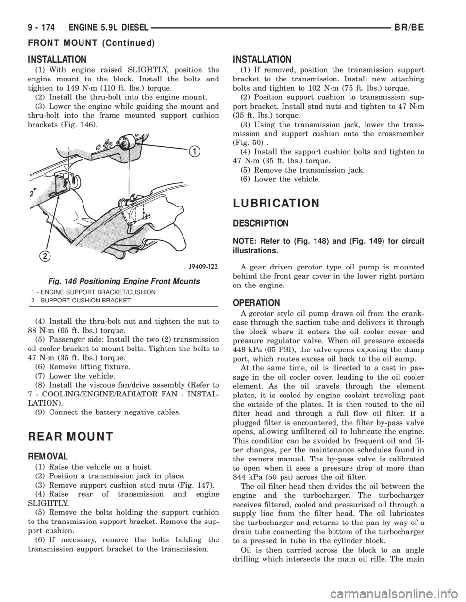
(3) Lower the engine while guiding the mount and
thru-bolt into the frame mounted support cushion
brackets (Fig. 146).
(4) Install the thru-bolt nut and tighten the nut to
88 N´m (65 ft. lbs.) torque.
(5) Passenger side: Install the two (2) transmission
oil cooler bracket to mount bolts. Tighten the bolts to
47 N´m (35 ft. lbs.) torque.
(6) Remove lifting fixture.
(7) Lower the vehicle.
(8) Install the viscous fan/drive assembly (Refer to
7 - COOLING/ENGINE/RADIATOR FAN - INSTAL-
LATION).
(9) Connect the battery negative cables.
REAR MOUNT
REMOVAL
(1) Raise the vehicle on a hoist.
(2) Position a transmission jack in place.
(3) Remove support cushion stud nuts (Fig. 147).
(4) Raise rear of transmission and engine
SLIGHTLY.
(5) Remove the bolts holding the support cushion
to the transmission support bracket. Remove the sup-
port cushion.
(6) If necessary, remove the bolts holding the
transmission support bracket to the transmission.
INSTALLATION
(1) If removed, position the transmission support
bracket to the transmission. Install new attaching
bolts and tighten to 102 N´m (75 ft. lbs.) torque.
(2) Position support cushion to transmission sup-
port bracket. Install stud nuts and tighten to 47 N´m
(35 ft. lbs.) torque.
(3) Using the transmission jack, lower the trans-
mission and support cushion onto the crossmember
(Fig. 50) .
(4) Install the support cushion bolts and tighten to
47 N´m (35 ft. lbs.) torque.
(5) Remove the transmission jack.
(6) Lower the vehicle.
LUBRICATION
DESCRIPTION
NOTE: Refer to (Fig. 148) and (Fig. 149) for circuit
illustrations.
A gear driven gerotor type oil pump is mounted
behind the front gear cover in the lower right portion
on the engine.
OPERATION
A gerotor style oil pump draws oil from the crank-
case through the suction tube and delivers it through
the block where it enters the oil cooler cover and
pressure regulator valve. When oil pressure exceeds
449 kPa (65 PSI), the valve opens exposing the dump
port, which routes excess oil back to the oil sump.
At the same time, oil is directed to a cast in pas-
sage in the oil cooler cover, leading to the oil cooler
element. As the oil travels through the element
plates, it is cooled by engine coolant traveling past
the outside of the plates. It is then routed to the oil
filter head and through a full flow oil filter. If a
plugged filter is encountered, the filter by-pass valve
opens, allowing unfiltered oil to lubricate the engine.
This condition can be avoided by frequent oil and fil-
ter changes, per the maintenance schedules found in
the owners manual. The by-pass valve is calibrated
to open when it sees a pressure drop of more than
344 kPa (50 psi) across the oil filter.
The oil filter head then divides the oil between the
engine and the turbocharger. The turbocharger
receives filtered, cooled and pressurized oil through a
supply line from the filter head. The oil lubricates
the turbocharger and returns to the pan by way of a
drain tube connecting the bottom of the turbocharger
to a pressed in tube in the cylinder block.
Oil is then carried across the block to an angle
drilling which intersects the main oil rifle. The main
Fig. 146 Positioning Engine Front Mounts
1 - ENGINE SUPPORT BRACKET/CUSHION
2 - SUPPORT CUSHION BRACKET
9 - 174 ENGINE 5.9L DIESELBR/BE
FRONT MOUNT (Continued)
Page 1253 of 2255

DIAGNOSIS AND TESTINGÐENGINE OIL
PRESSURE
(1) Remove the engine oil pressure sensor and
install Oil Pressure Line and Gauge Tool C-3292 with
a suitable adapter.
(2) Start engine and warm to operating tempera-
ture.
(3) Record engine oil pressure and compare with
engine oil pressure chart.
CAUTION: If engine oil pressure is zero at idle, DO
NOT RUN THE ENGINE.
Engine Oil Pressure (MIN)
At Idle 103.4 kPa (15 psi)
At 2000 rpm 310.2 kPa (45 psi)
If minimum engine oil pressure is below these
ranges, (Refer to 9 - ENGINE - DIAGNOSIS AND
TESTING).
(4) Remove oil pressure gauge and install the oil
pressure sensor. Tighten the sensor to 16 N´m (144
in. lbs.) torque.
OIL
STANDARD PROCEDURE
STANDARD PROCEDURE - ENGINE OIL LEVEL
CAUTION: Do not overfill crankcase with engine oil,
oil foaming and oil pressure loss can result.
To ensure proper lubrication of an engine, the
engine oil must be maintained at an acceptable level.
The acceptable oil level is in the SAFE RANGE on
the engine oil dipstick (Fig. 150).
Unless the engine has exhibited loss of oil pres-
sure, run the engine for about five minutes before
checking oil level. Checking engine oil level of a cold
engine is not accurate.
(1) Position vehicle on level surface.(2) With engine OFF, allow approximately ten min-
utes for oil to settle to bottom of crankcase, remove
engine oil dipstick.
(3) Wipe dipstick clean.
(4) Replace dipstick and verify it is seated in the
tube.
(5) Remove dipstick, with handle held above the
tip, take oil level reading.
(6) Add oil only if level is below the SAFE RANGE
area on the dipstick.
(7) Replace dipstick
STANDARD PROCEDURE - ENGINE OIL
SERVICE
WARNING: HOT OIL CAN CAUSE PERSONAL
INJURY.
NOTE: Change engine oil and filter at intervals
specified in the owner's manual.
(1) Operate the engine until the water tempera-
ture reaches 60ÉC (140ÉF). Shut the engine off.
(2) Use a container that can hold at least 14 liters
(15 quarts) to hold the used oil. Remove the oil drain
plug and drain the used engine oil into the container.
1 - ROCKER ARM
2 - ROCKER SHAFT
3 - PEDESTAL
4 - FROM MAIN OIL RIFLE
5 - TO VALVE TRAIN
6 - MAIN OIL RIFLE
7 - FROM MAIN OIL RIFLE
8 - TO CAMSHAFT9 - TO PISTON COOLING NOZZLE
10 - FROM OIL COOLER
11 - CRANKSHAFT MAIN JOURNAL
12 - ROD JOURNAL
13 - TO ROD BEARING
14 - MAIN OIL RIFLE
Fig. 150 Oil Level Indicator (Dipstick)
1 - ADD OIL MARK
2 - O-RING
3 - SAFE RANGE
9 - 178 ENGINE 5.9L DIESELBR/BE
LUBRICATION (Continued)