2002 DODGE RAM torque
[x] Cancel search: torquePage 1161 of 2255
INSTALLATION
INSTALLATIONÐCAMSHAFT BEARINGS
(1) Install new camshaft bearings using recom-
mended Tool 8544 Camshaft Bushing Remover
Installer, by sliding the new camshaft bearing shell
over proper adapter.
(2) Bearings must be carefully aligned to bring oil
holes into full register with oil passages from the
main bearing. If the camshaft bearing shell oil holes
are not in exact alignment, remove and install them
correctly. Install a new core hole plug at the rear of
camshaft.Be sure this plug does not leak.
INSTALLATIONÐCAMSHAFT
(1) Lubricate camshaft lobes and camshaft bearing
journals. Using a long bolt, insert the camshaft into
the cylinder block.
NOTE: Whenever an engine has been rebuilt, a new
camshaft and/or new tappets installed, add 1 pint of
MoparTCrankcase Conditioner, or equivalent. The
oil mixture should be left in engine for a minimum
of 805 km (500 miles). Drain at the next normal oil
change.
(2) Install camshaft thrust plate. Tighten the torx
bolts to 22 N´m (16 ft. lbs.) torque.
(3) Check camshaft end play. The end play should
be 0.051-0.152 mm (0.002-0.006 inch) with a new
thrust plate and up to 0.254 mm (0.010 inch) with a
used thrust plate. If not within these limits install a
new thrust plate.
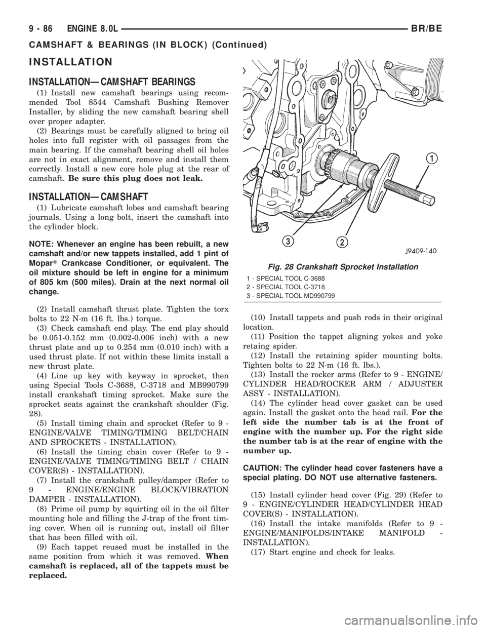
(4) Line up key with keyway in sprocket, then
using Special Tools C-3688, C-3718 and MB990799
install crankshaft timing sprocket. Make sure the
sprocket seats against the crankshaft shoulder (Fig.
28).
(5) Install timing chain and sprocket (Refer to 9 -
ENGINE/VALVE TIMING/TIMING BELT/CHAIN
AND SPROCKETS - INSTALLATION).
(6) Install the timing chain cover (Refer to 9 -
ENGINE/VALVE TIMING/TIMING BELT / CHAIN
COVER(S) - INSTALLATION).
(7) Install the crankshaft pulley/damper (Refer to
9 - ENGINE/ENGINE BLOCK/VIBRATION
DAMPER - INSTALLATION).
(8) Prime oil pump by squirting oil in the oil filter
mounting hole and filling the J-trap of the front tim-
ing cover. When oil is running out, install oil filter
that has been filled with oil.
(9) Each tappet reused must be installed in the
same position from which it was removed.When
camshaft is replaced, all of the tappets must be
replaced.(10) Install tappets and push rods in their original
location.
(11) Position the tappet aligning yokes and yoke
retaing spider.
(12) Install the retaining spider mounting bolts.
Tighten bolts to 22 N´m (16 ft. lbs.).
(13) Install the rocker arms (Refer to 9 - ENGINE/
CYLINDER HEAD/ROCKER ARM / ADJUSTER
ASSY - INSTALLATION).
(14) The cylinder head cover gasket can be used
again. Install the gasket onto the head rail.For the
left side the number tab is at the front of
engine with the number up. For the right side
the number tab is at the rear of engine with the
number up.
CAUTION: The cylinder head cover fasteners have a
special plating. DO NOT use alternative fasteners.
(15) Install cylinder head cover (Fig. 29) (Refer to
9 - ENGINE/CYLINDER HEAD/CYLINDER HEAD
COVER(S) - INSTALLATION).
(16) Install the intake manifolds (Refer to 9 -
ENGINE/MANIFOLDS/INTAKE MANIFOLD -
INSTALLATION).
(17) Start engine and check for leaks.
Fig. 28 Crankshaft Sprocket Installation
1 - SPECIAL TOOL C-3688
2 - SPECIAL TOOL C-3718
3 - SPECIAL TOOL MD990799
9 - 86 ENGINE 8.0LBR/BE
CAMSHAFT & BEARINGS (IN BLOCK) (Continued)
Page 1163 of 2255
(8) Remove the upper main bearings from the
block.
INSTALLATION
When a crankshaft is replaced, all main and con-
necting rod bearings should be replaced with new
bearings. Therefore, selective fitting of the bearings
is not required when a crankshaft and bearings are
replaced.
NOTE: Lubricate crankshaft main bearings with
clean engine oil.
(1) Position upper main bearings into block.
(2) Position the crankshaft into the cylinder block.
(3) Lubricate the main journals with clean engine
oil. Install upper main bearings, caps and bolts. Fol-
low the 2 step tightening sequence, starting with
main bearing cap 1.
(4) Lubricate the connecting rod bearings and jour-
nals with clean engine oil. Carefully install connect-
ing rods to the crankshaft.
(5) Using Special Tool 8359 Seal Installer install
new oil into oil seal retainer.
(6) Using Special Tool 6687 Guide, install the rear
seal retainer with a new gasket.
(7) Install the timing chain cover with a new gas-
ket and oil seal.
(8) Prime oil pump by squirt oil in the oil filter
mounting hole and filling the J-trap of the front tim-
ing cover. When oil is running out, install oil filter
that has been filled with oil.
(9) Apply a rearward axial load of 667 N (150
lbs-f) on crankshaft centerline, driving No.3 main cap
and thrust bearing against No.3 bulkhead. Repeat
procedure, driving crankshaft forward to align rear
flange of thrust bearings in a common plane. Front
face of No.1 main cap must not extend forward in
front of face of No.1 bulkhead.
(10) Install the oil pickup tube. Tighten the bolts
to 16 N´m (144 in. lbs.) torque.
(11) Install the oil pan.
CRANKSHAFT MAIN
BEARINGS
STANDARD PROCEDUREÐFITTING
CRANKSHAFT MAIN BEARINGS
Bearing caps are not interchangeable and should
be marked at removal to ensure correct assembly.
Upper and lower bearing halves are NOT inter-
changeable. All lower main bearing halves are inter-
changeable. Upper main bearing halves of No. 2, 4,
and 5 are interchangeable. Upper main bearinghalves of No. 1 and 6 are interchangeable, this also
applies to the lower bearing halves.
The No.3 main bearing is flanged to carry the
crankshaft thrust loads. This bearing is NOT inter-
changeable with any other bearing halves in the
engine. Bearing shells are available in standard and
the following undersizes: 0.25 mm (0.001 inch), 0.051
mm (0.002 inch), 0.076 mm (0.003 inch), 0.254 mm
(0.010 inch) and 0.305 mm (0.012 inch). Never install
an undersize bearing that will reduce clearance
below specifications.
REMOVAL
(1) Remove the oil pan and oil pump pick-up tube
(Refer to 9 - ENGINE/LUBRICATION/OIL PAN -
REMOVAL).
(2) Identify bearing caps before removal. Remove
bearing caps one at a time.
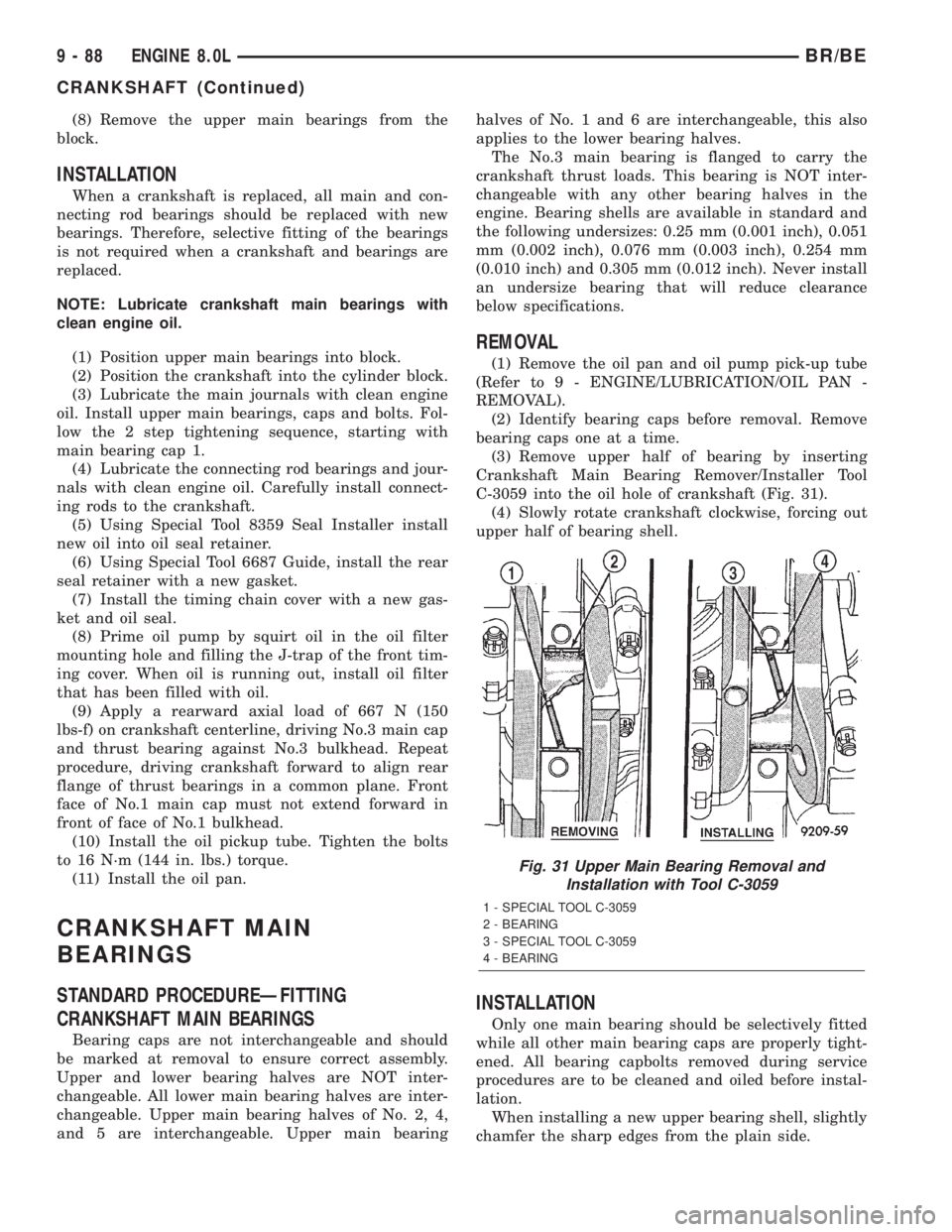
(3) Remove upper half of bearing by inserting
Crankshaft Main Bearing Remover/Installer Tool
C-3059 into the oil hole of crankshaft (Fig. 31).
(4) Slowly rotate crankshaft clockwise, forcing out
upper half of bearing shell.
INSTALLATION
Only one main bearing should be selectively fitted
while all other main bearing caps are properly tight-
ened. All bearing capbolts removed during service
procedures are to be cleaned and oiled before instal-
lation.
When installing a new upper bearing shell, slightly
chamfer the sharp edges from the plain side.
Fig. 31 Upper Main Bearing Removal and
Installation with Tool C-3059
1 - SPECIAL TOOL C-3059
2 - BEARING
3 - SPECIAL TOOL C-3059
4 - BEARING
9 - 88 ENGINE 8.0LBR/BE
CRANKSHAFT (Continued)
Page 1168 of 2255
37). Install the yoke retaining spider bolts and
tighten to 22 N´m (16 ft. lbs.) torque.
(4) Install the push rods in their original location.
(5) Install the rocker arms (Refer to 9 - ENGINE/
CYLINDER HEAD/ROCKER ARM / ADJUSTER
ASSY - INSTALLATION).
(6) Install lower and upper intake manifold (Refer
to 9 - ENGINE/MANIFOLDS/INTAKE MANIFOLD -
INSTALLATION).
(7) The cylinder head cover gasket can be used
again. Install the gasket onto the head rail.For the
left side the number tab is at the front of
engine with the number up. For the right side
the number tab is at the rear of engine with the
number up.
(8) Install cylinder head cover (Refer to 9 -
ENGINE/CYLINDER HEAD/CYLINDER HEAD
COVER(S) - INSTALLATION).
(9) Install the air cleaner.
CAUTION: To prevent damage to valve mechanism,
engine must not be run above fast idle until all
hydraulic tappets have filled with oil and have
become quiet.
(10) Connect the negative cable to the battery.
(11) Road test vehicle and check for leaks.
PISTON & CONNECTING ROD
DESCRIPTION
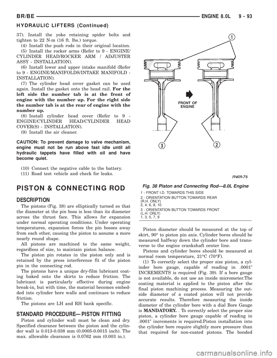
The pistons (Fig. 38) are elliptically turned so that
the diameter at the pin boss is less than its diameter
across the thrust face. This allows for expansion
under normal operating conditions. Under operating
temperatures, expansion forces the pin bosses away
from each other, causing the piston to assume a more
nearly round shape.
All pistons are machined to the same weight,
regardless of size, to maintain piston balance.
The piston pin rotates in the piston only and is
retained by the press interference fit of the piston
pin in the connecting rod.
The pistons have a unique dry-film lubricant coat-
ing baked onto the skirts to reduce friction. The
lubricant is particularly effective during engine
break-in, but with time, the material becomes embed-
ded into cylinder bore walls and continues to reduce
friction.
The pistons are LH and RH bank specific.
STANDARD PROCEDUREÐPISTON FITTING
Piston and cylinder wall must be clean and dry.
Specified clearance between the piston and the cylin-
der wall is 0.013-0.038 mm (0.0005-0.0015 inch). The
max. allowable clearance is 0.0762 mm (0.003 in.).Piston diameter should be measured at the top of
skirt, 90É to piston pin axis. Cylinder bores should be
measured halfway down the cylinder bore and trans-
verse to the engine crankshaft center line.
Pistons and cylinder bores should be measured at
normal room temperature, 21ÉC (70ÉF).
(1) To correctly select the proper size piston, a cyl-
inder bore gauge, capable of reading in .00019
INCREMENTS is required (Fig. 39). If a bore gauge
is not available, do not use an inside micrometer.The
coating material is applied to the piston after the
final piston machining process. Measuring the out-
side diameter of a coated piston will not provide
accurate results. Therefore measuring the inside
diameter of the cylinder bore with a dial Bore Gauge
isMANDATORY.. To correctly select the proper size
piston, a cylinder bore gauge capable of reading in
.00019increments is required.Piston installation into
the cylinder bore require slightly more pressure than
that required for non-coated pistons. The bonded
Fig. 38 Piston and Connecting RodÐ8.0L Engine
1 - FRONT I.D. TOWARDS THIS SIDE
2 - ORIENTATION BUTTON TOWARDS REAR
(R.H. ONLY)
2, 4, 6, 8, 10
3 - ORIENTATION BUTTON TOWARDS FRONT
(L.H. ONLY)
1, 3, 5, 7, 9
BR/BEENGINE 8.0L 9 - 93
HYDRAULIC LIFTERS (Continued)
Page 1170 of 2255
(10) Install rod caps. Install nuts on cleaned and
oiled rod bolts and tighten nuts to 61 N´m (45 ft. lbs.)
torque.
(11) Install the oil pump pick-up tube and oil pan
(Refer to 9 - ENGINE/LUBRICATION/OIL PAN -
INSTALLATION).
(12) Install the cylinder head (Refer to 9 -
ENGINE/CYLINDER HEAD - INSTALLATION) and
cylinder head cover (Refer to 9 - ENGINE/CYLIN-
DER HEAD/CYLINDER HEAD COVER(S) -
INSTALLATION).
(13) Install intake manifold (Refer to 9 - ENGINE/
MANIFOLDS/INTAKE MANIFOLD - INSTALLA-
TION).
(14) Install the engine into the vehicle (Refer to 9 -
ENGINE - INSTALLATION).
PISTON RINGS
STANDARD PROCEDUREÐFITTING PISTON
RINGS
(1) Measurement of end gaps:
(a) Measure piston ring gap 2 inches from bot-
tom of cylinder bore. An inverted piston can be
used to push the rings down to ensure positioning
rings squarely in the cylinder bore before measur-
ing.
(b) Insert feeler stock in the gap. Gap for com-
pression rings should be between 0.254-0.508 mm
(0.010-0.020 inch). The oil ring gap should be
0.381- 1.397 mm (0.015-0.055 inch).
(c) Rings with insufficient end gap may be prop-
erly filed to the correct dimension. Ends should bestoned smooth after filing with Arkansas White
Stone. Rings with excess gaps should not be used.
(2) Install rings and confirm ring side clearance:
(a) Install oil rings being careful not to nick or
scratch the piston. Install the oil control rings
according to instructions in the package. It is not
necessary to use a tool to install the upper and
lower rails. Insert oil rail spacer first, then side
rails.
(b) Install the second compression rings using
Installation Tool C-4184. The compression rings
must be installed with the identification mark face
up (toward top of piston) and chamfer facing down.
An identification mark on the ring is a drill point,
a stamped letter O, an oval depression or the word
TOP (Fig. 42) (Fig. 44).
(c) Using a ring installer, install the top com-
pression ring with the chamfer facing up (Fig. 44).
An identification mark on the ring is a drill point,
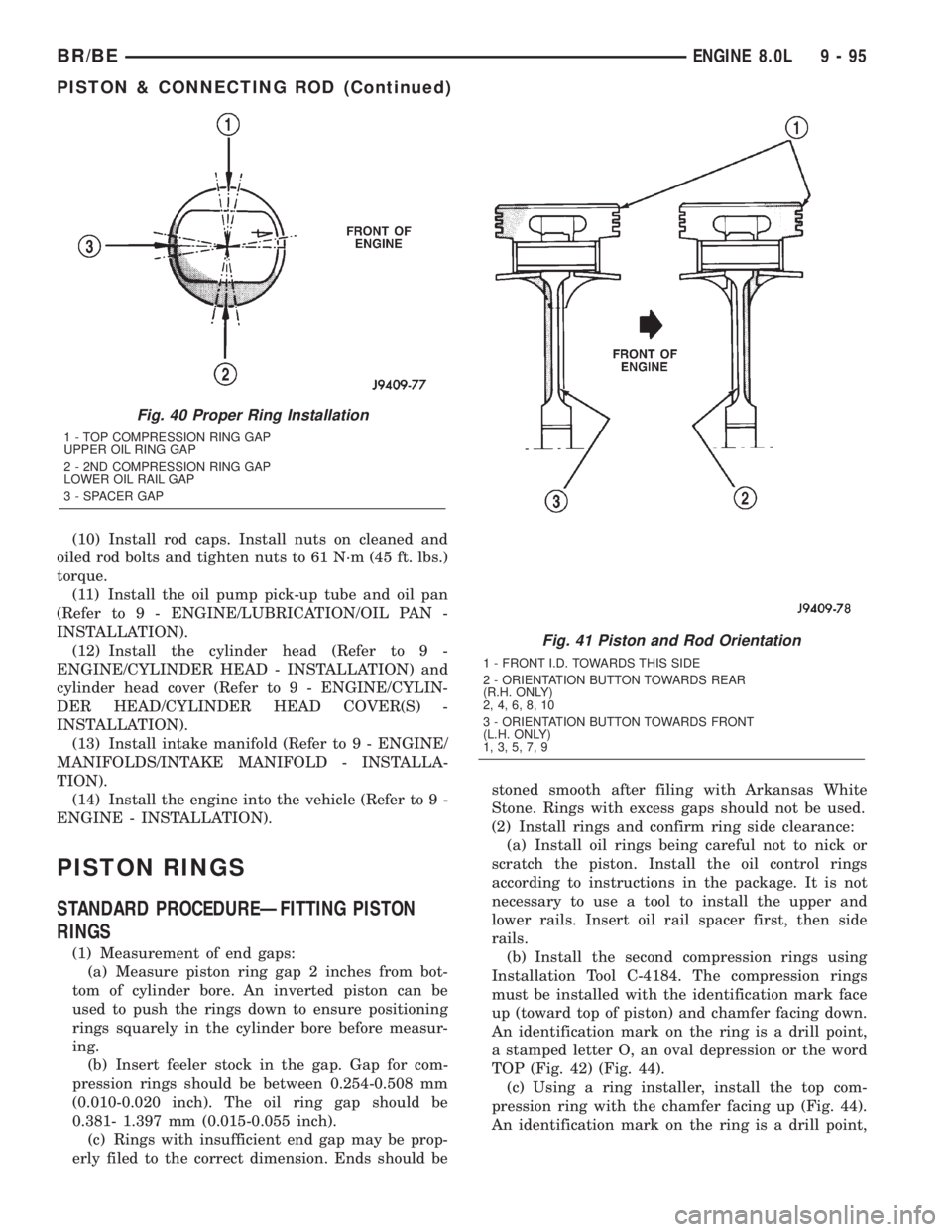
Fig. 40 Proper Ring Installation
1 - TOP COMPRESSION RING GAP
UPPER OIL RING GAP
2 - 2ND COMPRESSION RING GAP
LOWER OIL RAIL GAP
3 - SPACER GAP
Fig. 41 Piston and Rod Orientation
1 - FRONT I.D. TOWARDS THIS SIDE
2 - ORIENTATION BUTTON TOWARDS REAR
(R.H. ONLY)
2, 4, 6, 8, 10
3 - ORIENTATION BUTTON TOWARDS FRONT
(L.H. ONLY)
1, 3, 5, 7, 9
BR/BEENGINE 8.0L 9 - 95
PISTON & CONNECTING ROD (Continued)
Page 1172 of 2255
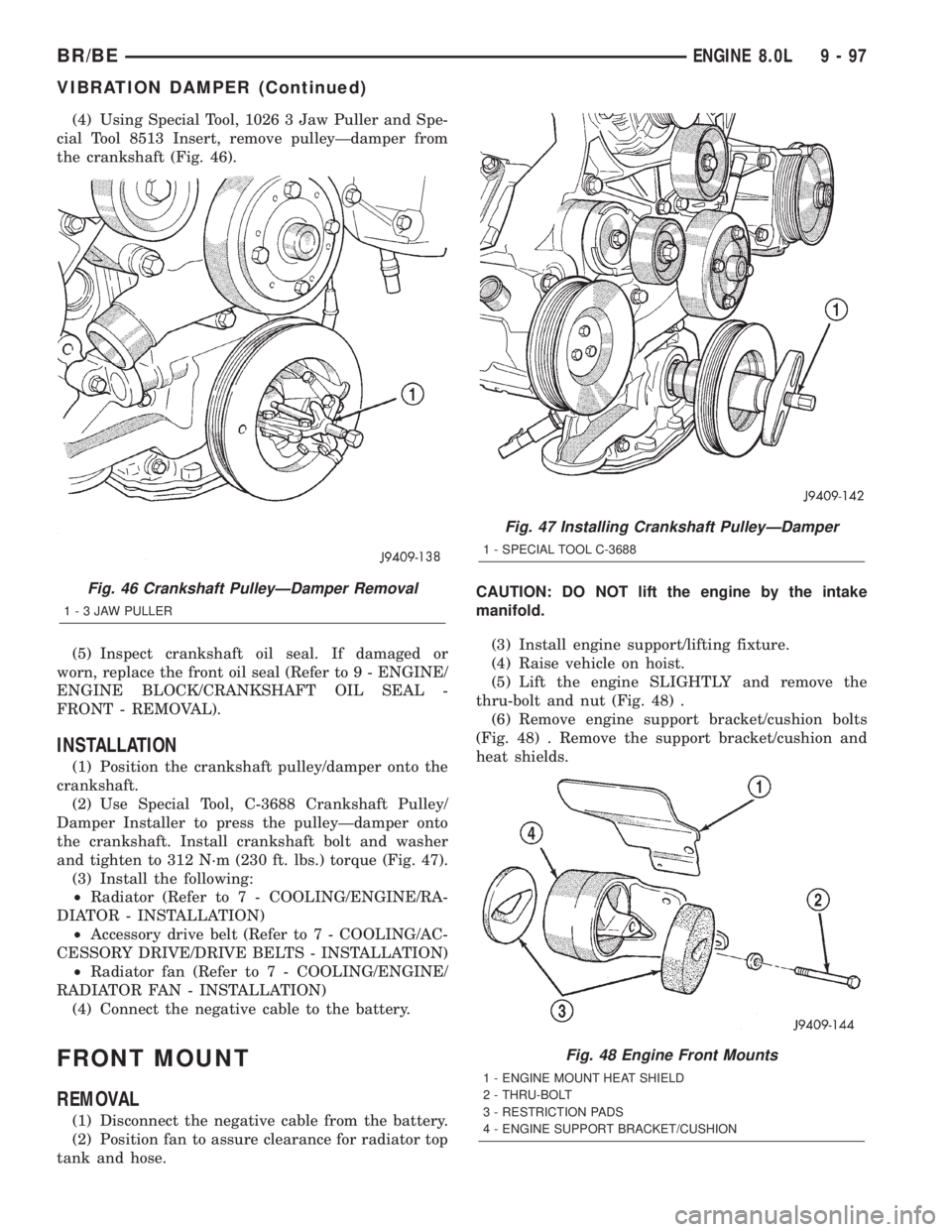
(4) Using Special Tool, 1026 3 Jaw Puller and Spe-
cial Tool 8513 Insert, remove pulleyÐdamper from
the crankshaft (Fig. 46).
(5) Inspect crankshaft oil seal. If damaged or
worn, replace the front oil seal (Refer to 9 - ENGINE/
ENGINE BLOCK/CRANKSHAFT OIL SEAL -
FRONT - REMOVAL).
INSTALLATION
(1) Position the crankshaft pulley/damper onto the
crankshaft.
(2) Use Special Tool, C-3688 Crankshaft Pulley/
Damper Installer to press the pulleyÐdamper onto
the crankshaft. Install crankshaft bolt and washer
and tighten to 312 N´m (230 ft. lbs.) torque (Fig. 47).
(3) Install the following:
²Radiator (Refer to 7 - COOLING/ENGINE/RA-
DIATOR - INSTALLATION)
²Accessory drive belt (Refer to 7 - COOLING/AC-
CESSORY DRIVE/DRIVE BELTS - INSTALLATION)
²Radiator fan (Refer to 7 - COOLING/ENGINE/
RADIATOR FAN - INSTALLATION)
(4) Connect the negative cable to the battery.
FRONT MOUNT
REMOVAL
(1) Disconnect the negative cable from the battery.
(2) Position fan to assure clearance for radiator top
tank and hose.CAUTION: DO NOT lift the engine by the intake
manifold.
(3) Install engine support/lifting fixture.
(4) Raise vehicle on hoist.
(5) Lift the engine SLIGHTLY and remove the
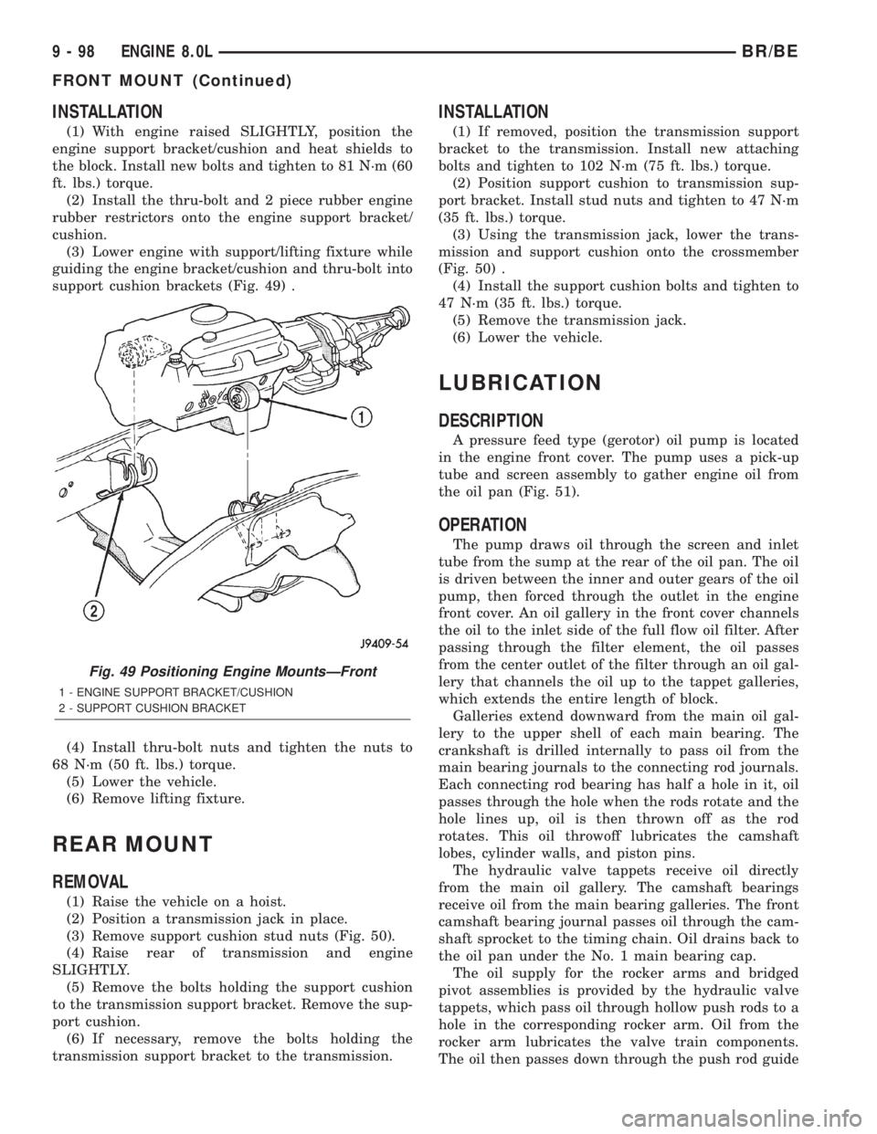
thru-bolt and nut (Fig. 48) .
(6) Remove engine support bracket/cushion bolts
(Fig. 48) . Remove the support bracket/cushion and
heat shields.
Fig. 46 Crankshaft PulleyÐDamper Removal
1-3JAWPULLER
Fig. 47 Installing Crankshaft PulleyÐDamper
1 - SPECIAL TOOL C-3688
Fig. 48 Engine Front Mounts
1 - ENGINE MOUNT HEAT SHIELD
2 - THRU-BOLT
3 - RESTRICTION PADS
4 - ENGINE SUPPORT BRACKET/CUSHION
BR/BEENGINE 8.0L 9 - 97
VIBRATION DAMPER (Continued)
Page 1173 of 2255
INSTALLATION
(1) With engine raised SLIGHTLY, position the
engine support bracket/cushion and heat shields to
the block. Install new bolts and tighten to 81 N´m (60
ft. lbs.) torque.
(2) Install the thru-bolt and 2 piece rubber engine
rubber restrictors onto the engine support bracket/
cushion.
(3) Lower engine with support/lifting fixture while
guiding the engine bracket/cushion and thru-bolt into
support cushion brackets (Fig. 49) .
(4) Install thru-bolt nuts and tighten the nuts to
68 N´m (50 ft. lbs.) torque.
(5) Lower the vehicle.
(6) Remove lifting fixture.
REAR MOUNT
REMOVAL
(1) Raise the vehicle on a hoist.
(2) Position a transmission jack in place.
(3) Remove support cushion stud nuts (Fig. 50).
(4) Raise rear of transmission and engine
SLIGHTLY.
(5) Remove the bolts holding the support cushion
to the transmission support bracket. Remove the sup-
port cushion.
(6) If necessary, remove the bolts holding the
transmission support bracket to the transmission.
INSTALLATION
(1) If removed, position the transmission support
bracket to the transmission. Install new attaching
bolts and tighten to 102 N´m (75 ft. lbs.) torque.
(2) Position support cushion to transmission sup-
port bracket. Install stud nuts and tighten to 47 N´m
(35 ft. lbs.) torque.
(3) Using the transmission jack, lower the trans-
mission and support cushion onto the crossmember
(Fig. 50) .
(4) Install the support cushion bolts and tighten to
47 N´m (35 ft. lbs.) torque.
(5) Remove the transmission jack.
(6) Lower the vehicle.
LUBRICATION
DESCRIPTION
A pressure feed type (gerotor) oil pump is located
in the engine front cover. The pump uses a pick-up
tube and screen assembly to gather engine oil from
the oil pan (Fig. 51).
OPERATION
The pump draws oil through the screen and inlet
tube from the sump at the rear of the oil pan. The oil
is driven between the inner and outer gears of the oil
pump, then forced through the outlet in the engine
front cover. An oil gallery in the front cover channels
the oil to the inlet side of the full flow oil filter. After
passing through the filter element, the oil passes
from the center outlet of the filter through an oil gal-
lery that channels the oil up to the tappet galleries,
which extends the entire length of block.
Galleries extend downward from the main oil gal-
lery to the upper shell of each main bearing. The
crankshaft is drilled internally to pass oil from the
main bearing journals to the connecting rod journals.
Each connecting rod bearing has half a hole in it, oil
passes through the hole when the rods rotate and the
hole lines up, oil is then thrown off as the rod
rotates. This oil throwoff lubricates the camshaft
lobes, cylinder walls, and piston pins.
The hydraulic valve tappets receive oil directly
from the main oil gallery. The camshaft bearings
receive oil from the main bearing galleries. The front
camshaft bearing journal passes oil through the cam-
shaft sprocket to the timing chain. Oil drains back to
the oil pan under the No. 1 main bearing cap.
The oil supply for the rocker arms and bridged
pivot assemblies is provided by the hydraulic valve
tappets, which pass oil through hollow push rods to a
hole in the corresponding rocker arm. Oil from the
rocker arm lubricates the valve train components.
The oil then passes down through the push rod guide
Fig. 49 Positioning Engine MountsÐFront
1 - ENGINE SUPPORT BRACKET/CUSHION
2 - SUPPORT CUSHION BRACKET
9 - 98 ENGINE 8.0LBR/BE
FRONT MOUNT (Continued)
Page 1178 of 2255
(3) Drain engine oil.
(4) Remove left engine to transmission strut.
(5) Remove oil pan mounting bolts, pan and one-
piece gasket. The engine may have to be raised
slightly on 2WD vehicles.
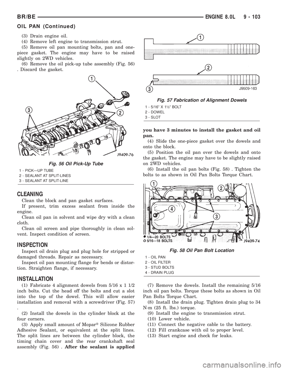
(6) Remove the oil pick-up tube assembly (Fig. 56)
. Discard the gasket.
CLEANING
Clean the block and pan gasket surfaces.
If present, trim excess sealant from inside the
engine.
Clean oil pan in solvent and wipe dry with a clean
cloth.
Clean oil screen and pipe thoroughly in clean sol-
vent. Inspect condition of screen.
INSPECTION
Inspect oil drain plug and plug hole for stripped or
damaged threads. Repair as necessary.
Inspect oil pan mounting flange for bends or distor-
tion. Straighten flange, if necessary.
INSTALLATION
(1) Fabricate 4 alignment dowels from 5/16x11/2
inch bolts. Cut the head off the bolts and cut a slot
into the top of the dowel. This will allow easier
installation and removal with a screwdriver (Fig. 57)
.
(2) Install the dowels in the cylinder block at the
four corners.
(3) Apply small amount of MopartSilicone Rubber
Adhesive Sealant, or equivalent at the split lines.
The split lines are between the cylinder block, the
timing chain cover and the rear crankshaft seal
assembly (Fig. 56) .After the sealant is appliedyou have 3 minutes to install the gasket and oil
pan.
(4) Slide the one-piece gasket over the dowels and
onto the block.
(5) Position the oil pan over the dowels and onto
the gasket. The engine may have to be slightly raised
on 2WD vehicles.
(6) Install the oil pan bolts (Fig. 58) . Tighten the
bolts to as shown in Oil Pan Bolts Torque Chart.
(7) Remove the dowels. Install the remaining 5/16
inch oil pan bolts. Torque these bolts as shown in Oil
Pan Bolts Torque Chart.
(8) Install the drain plug. Tighten drain plug to 34
N´m (25 ft. lbs.) torque.
(9) Install the engine to transmission strut.
(10) Lower vehicle.
(11) Connect the negative cable to the battery.
(12) Fill crankcase with oil to proper level.
(13) Start engine and check for leaks.
Fig. 56 Oil Pick-Up Tube
1 - PICKÐUP TUBE
2 - SEALANT AT SPLIT-LINES
3 - SEALANT AT SPLIT-LINE
Fig. 57 Fabrication of Alignment Dowels
1 - 5/16º X 1óº BOLT
2 - DOWEL
3 - SLOT
Fig. 58 Oil Pan Bolt Location
1 - OIL PAN
2 - OIL FILTER
3 - STUD BOLTS
4 - DRAIN PLUG
BR/BEENGINE 8.0L 9 - 103
OIL PAN (Continued)
Page 1181 of 2255
when compressed to 34 mm (1-11/32 inches). Replace
spring that fails to meet these specifications.
If oil pressure was low and pump is within specifi-
cations, inspect for worn engine bearings or other
reasons for oil pressure loss.
INSTALLATION
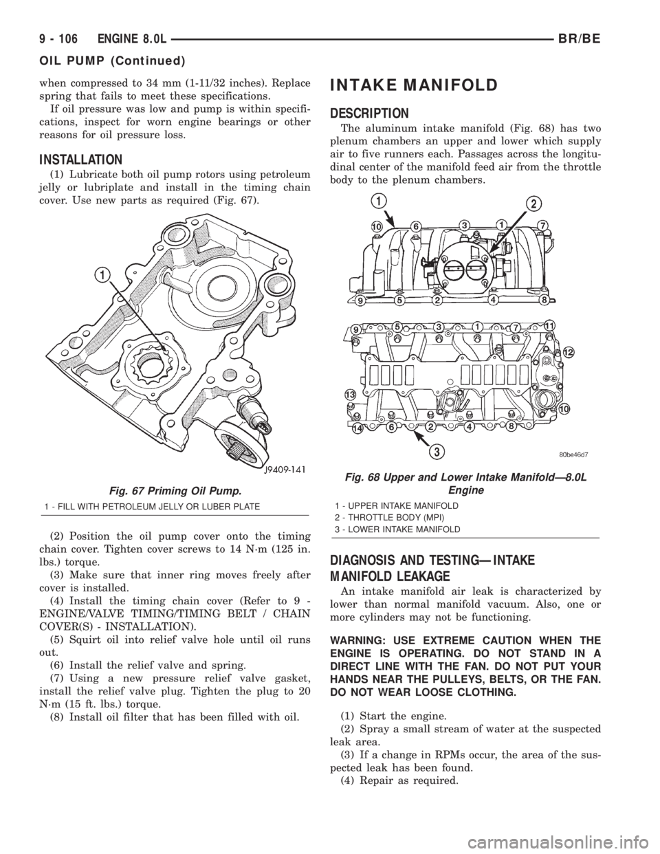
(1) Lubricate both oil pump rotors using petroleum
jelly or lubriplate and install in the timing chain
cover. Use new parts as required (Fig. 67).
(2) Position the oil pump cover onto the timing
chain cover. Tighten cover screws to 14 N´m (125 in.
lbs.) torque.
(3) Make sure that inner ring moves freely after
cover is installed.
(4) Install the timing chain cover (Refer to 9 -
ENGINE/VALVE TIMING/TIMING BELT / CHAIN
COVER(S) - INSTALLATION).
(5) Squirt oil into relief valve hole until oil runs
out.
(6) Install the relief valve and spring.
(7) Using a new pressure relief valve gasket,
install the relief valve plug. Tighten the plug to 20
N´m (15 ft. lbs.) torque.
(8) Install oil filter that has been filled with oil.
INTAKE MANIFOLD
DESCRIPTION
The aluminum intake manifold (Fig. 68) has two
plenum chambers an upper and lower which supply
air to five runners each. Passages across the longitu-
dinal center of the manifold feed air from the throttle
body to the plenum chambers.
DIAGNOSIS AND TESTINGÐINTAKE
MANIFOLD LEAKAGE
An intake manifold air leak is characterized by
lower than normal manifold vacuum. Also, one or
more cylinders may not be functioning.
WARNING: USE EXTREME CAUTION WHEN THE
ENGINE IS OPERATING. DO NOT STAND IN A
DIRECT LINE WITH THE FAN. DO NOT PUT YOUR
HANDS NEAR THE PULLEYS, BELTS, OR THE FAN.
DO NOT WEAR LOOSE CLOTHING.
(1) Start the engine.
(2) Spray a small stream of water at the suspected
leak area.
(3) If a change in RPMs occur, the area of the sus-
pected leak has been found.
(4) Repair as required.
Fig. 67 Priming Oil Pump.
1 - FILL WITH PETROLEUM JELLY OR LUBER PLATE
Fig. 68 Upper and Lower Intake ManifoldÐ8.0L
Engine
1 - UPPER INTAKE MANIFOLD
2 - THROTTLE BODY (MPI)
3 - LOWER INTAKE MANIFOLD
9 - 106 ENGINE 8.0LBR/BE
OIL PUMP (Continued)