2002 DODGE RAM torque
[x] Cancel search: torquePage 1213 of 2255
INSPECTION
The cylinder head cover gasket and isolators
are reusable.However, should cracks be present in
the rubber/silicone construction, the defective compo-
nents should be replaced.
INSTALLATION
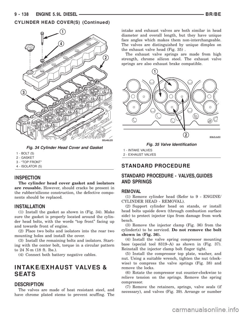
(1) Install the gasket as shown in (Fig. 34). Make
sure the gasket is properly located around the cylin-
der head bolts, with the words ªtop frontº facing up
and towards front of engine.
(2) Place two bolts and isolators into the rear two
mounting holes and install the cover.
(3) Install the remaining bolts and isolators. Start-
ing with the center bolt, torque in a circular pattern
to 24 N´m (18 ft. lbs.).
(4) Connect both battery negative cables.
INTAKE/EXHAUST VALVES &
SEATS
DESCRIPTION
The valves are made of heat resistant steel, and
have chrome plated stems to prevent scuffing. Theintake and exhaust valves are both similar in head
diameter and overall length, but they have unique
face angles which makes them non-interchangeable.
The valves are distinguished by unique dimples on
the exhaust valve head (Fig. 35) .
The exhaust valve springs are made from high
strength, chrome silicon steel. The exhaust valve
springs are also exhaust brake compatible.
STANDARD PROCEDURE
STANDARD PROCEDURE - VALVES,GUIDES
AND SPRINGS
REMOVAL
(1) Remove cylinder head (Refer to 9 - ENGINE/
CYLINDER HEAD - REMOVAL).
(2) Support cylinder head on stands, or install
head bolts upside down (through combustion surface
side) to protect injector tips from damage from work
bench.
(3) Remove the injector clamp (Fig. 36) from the
cylinder(s) to be serviced.Do not remove the bolt
shown in (Fig. 36).
(4) Install the valve spring compressor mounting
base (special tool 8319±A) as shown in (Fig. 37).
Reinstall the injector clamp bolt finger tight.
(5) Install the compressor top plate, washer, and
nut. Using a suitable wrench, tighten the nut (clock-
wise) to compress the valve springs (Fig. 38) and
remove the locks.
(6) Rotate the compressor nut counter-clockwise to
relieve tension on the springs. Remove the spring
compressor.
(7) Remove the retainers, springs, valve seals (if
necessary), and valves (Fig. 39). Arrange or number
Fig. 34 Cylinder Head Cover and Gasket
1 - BOLT (5)
2 - GASKET
3 - ªTOP FRONTº
4 - ISOLATOR (5)
Fig. 35 Valve Identification
1 - INTAKE VALVES
2 - EXHAUST VALVES
9 - 138 ENGINE 5.9L DIESELBR/BE
CYLINDER HEAD COVER(S) (Continued)
Page 1215 of 2255
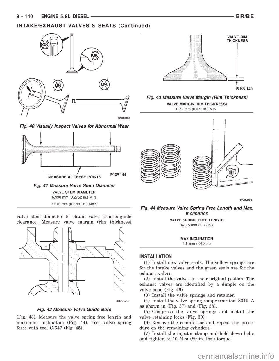
valve stem diameter to obtain valve stem-to-guide
clearance. Measure valve margin (rim thickness)
(Fig. 43). Measure the valve spring free length and
maximum inclination (Fig. 44). Test valve spring
force with tool C-647 (Fig. 45).
INSTALLATION
(1) Install new valve seals. The yellow springs are
for the intake valves and the green seals are for the
exhaust valves.
(2) Install the valves in their original postion. The
exhaust valves are identified by a dimple on the
valve head (Fig. 46).
(3) Install the valve springs and retainer.
(4) Install the valve spring compressor tool 8319±A
as shown in (Fig. 37) and (Fig. 38).
(5) Compress the valve springs and install the
valve retaining locks (Fig. 39).
(6) Remove the compressor and repeat the proce-
dure on the remaining cylinders.
(7) Install the injector clamp and hold down bolts
and tighten to 10 N´m (89 in. lbs.) torque.
Fig. 40 Visually Inspect Valves for Abnormal Wear
Fig. 41 Measure Valve Stem Diameter
VALVE STEM DIAMETER
6.990 mm (0.2752 in.) MIN
7.010 mm (0.2760 in.) MAX
Fig. 42 Measure Valve Guide Bore
Fig. 43 Measure Valve Margin (Rim Thickness)
VALVE MARGIN (RIM THICKNESS)
0.72 mm (0.031 in.) MIN.
Fig. 44 Measure Valve Spring Free Length and Max.
Inclination
VALVE SPRING FREE LENGTH
47.75 mm (1.88 in.)
MAX INCLINATION
1.5 mm (.059 in.)
9 - 140 ENGINE 5.9L DIESELBR/BE
INTAKE/EXHAUST VALVES & SEATS (Continued)
Page 1218 of 2255
(9) Install the cylinder head cover (Fig. 47) (Refer
to 9 - ENGINE/CYLINDER HEAD/CYLINDER
HEAD COVER(S) - INSTALLATION).
(10) Install the fuel pump gear access cover.
(11) Connect the battery negative cables.
REMOVAL
(1) Disconnect the battery negative cables.
(2) Remove the cylinder head cover (Fig. 52) (Refer
to 9 - ENGINE/CYLINDER HEAD/CYLINDER
HEAD COVER(S) - REMOVAL).
(3) Remove the rocker arms and crossheads (Fig.
53) from the cylinder(s) to be serviced. Mark each
component so they can be installed in their original
position.
(4) Remove the crankcase breather vapor canister
and breather housing (Fig. 55).
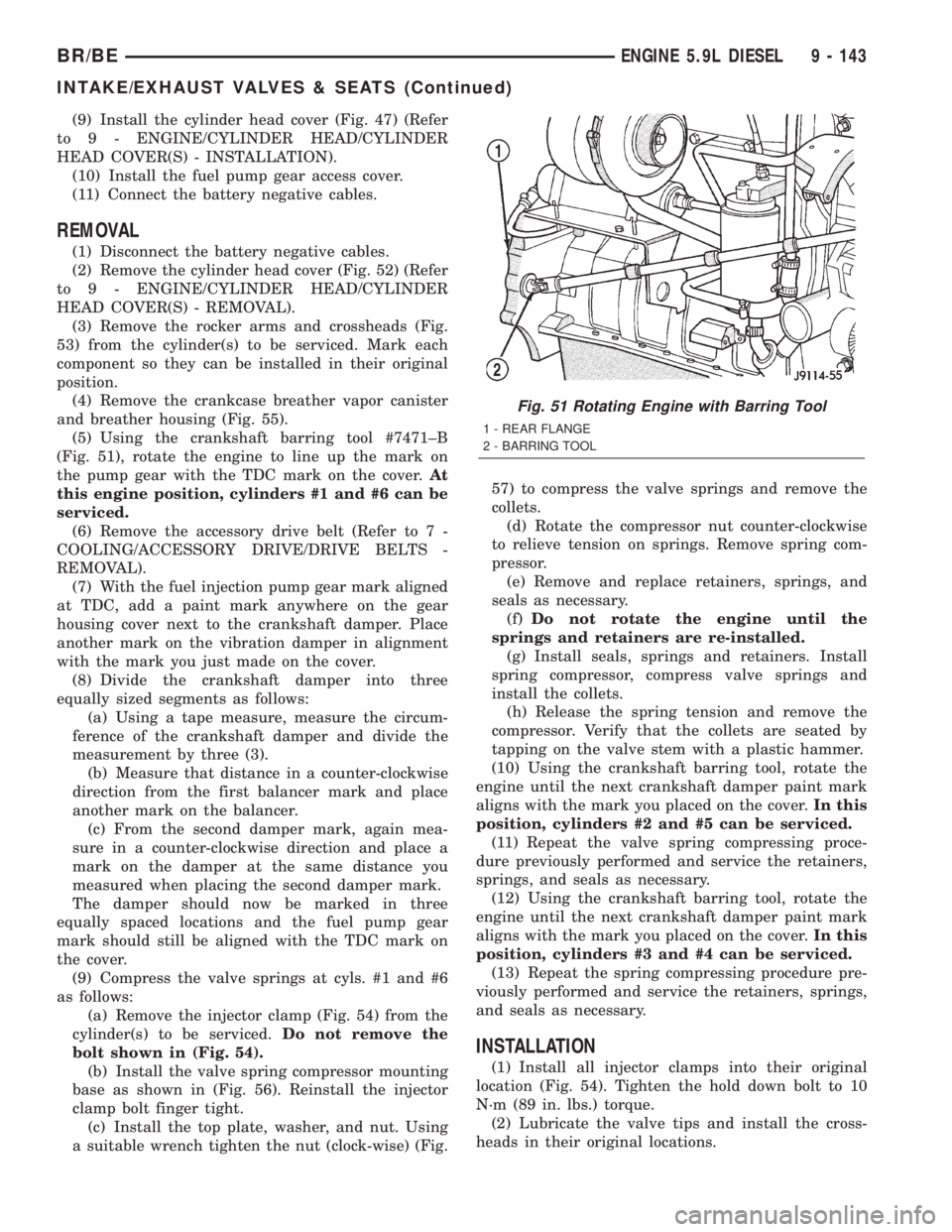
(5) Using the crankshaft barring tool #7471±B
(Fig. 51), rotate the engine to line up the mark on
the pump gear with the TDC mark on the cover.At
this engine position, cylinders #1 and #6 can be
serviced.
(6) Remove the accessory drive belt (Refer to 7 -
COOLING/ACCESSORY DRIVE/DRIVE BELTS -
REMOVAL).
(7) With the fuel injection pump gear mark aligned
at TDC, add a paint mark anywhere on the gear
housing cover next to the crankshaft damper. Place
another mark on the vibration damper in alignment
with the mark you just made on the cover.
(8) Divide the crankshaft damper into three
equally sized segments as follows:
(a) Using a tape measure, measure the circum-
ference of the crankshaft damper and divide the
measurement by three (3).
(b) Measure that distance in a counter-clockwise
direction from the first balancer mark and place
another mark on the balancer.
(c) From the second damper mark, again mea-
sure in a counter-clockwise direction and place a
mark on the damper at the same distance you
measured when placing the second damper mark.
The damper should now be marked in three
equally spaced locations and the fuel pump gear
mark should still be aligned with the TDC mark on
the cover.
(9) Compress the valve springs at cyls. #1 and #6
as follows:
(a) Remove the injector clamp (Fig. 54) from the
cylinder(s) to be serviced.Do not remove the
bolt shown in (Fig. 54).
(b) Install the valve spring compressor mounting
base as shown in (Fig. 56). Reinstall the injector
clamp bolt finger tight.
(c) Install the top plate, washer, and nut. Using
a suitable wrench tighten the nut (clock-wise) (Fig.57) to compress the valve springs and remove the
collets.
(d) Rotate the compressor nut counter-clockwise
to relieve tension on springs. Remove spring com-
pressor.
(e) Remove and replace retainers, springs, and
seals as necessary.
(f)Do not rotate the engine until the
springs and retainers are re-installed.
(g) Install seals, springs and retainers. Install
spring compressor, compress valve springs and
install the collets.
(h) Release the spring tension and remove the
compressor. Verify that the collets are seated by
tapping on the valve stem with a plastic hammer.
(10) Using the crankshaft barring tool, rotate the
engine until the next crankshaft damper paint mark
aligns with the mark you placed on the cover.In this
position, cylinders #2 and #5 can be serviced.
(11) Repeat the valve spring compressing proce-
dure previously performed and service the retainers,
springs, and seals as necessary.
(12) Using the crankshaft barring tool, rotate the
engine until the next crankshaft damper paint mark
aligns with the mark you placed on the cover.In this
position, cylinders #3 and #4 can be serviced.
(13) Repeat the spring compressing procedure pre-
viously performed and service the retainers, springs,
and seals as necessary.
INSTALLATION
(1) Install all injector clamps into their original
location (Fig. 54). Tighten the hold down bolt to 10
N´m (89 in. lbs.) torque.
(2) Lubricate the valve tips and install the cross-
heads in their original locations.
Fig. 51 Rotating Engine with Barring Tool
1 - REAR FLANGE
2 - BARRING TOOL
BR/BEENGINE 5.9L DIESEL 9 - 143
INTAKE/EXHAUST VALVES & SEATS (Continued)
Page 1220 of 2255
original locations (Fig. 53). Tighten bolts to 36 N´m
(27 ft. lbs.) torque.
(4)Verify valve lash adjustment (Refer to 9 -
ENGINE/CYLINDER HEAD/INTAKE/EXHAUST
VALVES & SEATS - STANDARD PROCEDURE).
(5) Install cylinder head cover and reusable gasket
(Fig. 52) (Refer to 9 - ENGINE/CYLINDER HEAD/
CYLINDER HEAD COVER(S) - INSTALLATION).
(6) Install the accessory drive belt (Refer to 7 -
COOLING/ACCESSORY DRIVE/DRIVE BELTS -
INSTALLATION).
(7) Connect battery negative cables.
ROCKER ARM / ADJUSTER
ASSY
DESCRIPTION
The 24±valve overhead system incorporates rocker
arms that are designed to allow fuel injector service
without removing the rocker arms and pedestals. The
unique intake and exhaust rocker arms have their
own rocker shafts and are lubricated by passages
intersecting the cylinder block main oil rifle. Cross-
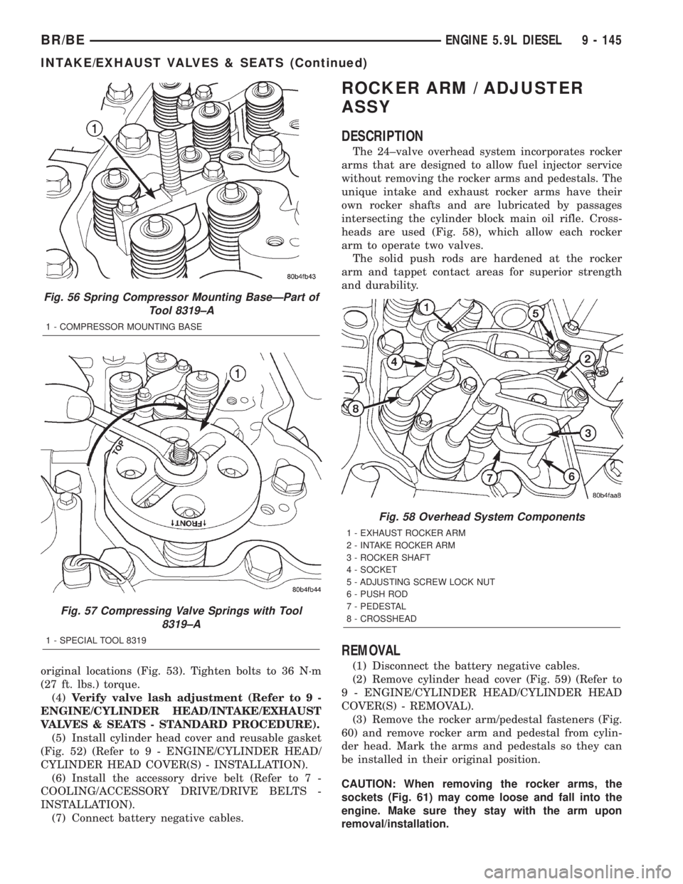
heads are used (Fig. 58), which allow each rocker
arm to operate two valves.
The solid push rods are hardened at the rocker
arm and tappet contact areas for superior strength
and durability.
REMOVAL
(1) Disconnect the battery negative cables.
(2) Remove cylinder head cover (Fig. 59) (Refer to
9 - ENGINE/CYLINDER HEAD/CYLINDER HEAD
COVER(S) - REMOVAL).
(3) Remove the rocker arm/pedestal fasteners (Fig.
60) and remove rocker arm and pedestal from cylin-
der head. Mark the arms and pedestals so they can
be installed in their original position.
CAUTION: When removing the rocker arms, the
sockets (Fig. 61) may come loose and fall into the
engine. Make sure they stay with the arm upon
removal/installation.
Fig. 56 Spring Compressor Mounting BaseÐPart of
Tool 8319±A
1 - COMPRESSOR MOUNTING BASE
Fig. 57 Compressing Valve Springs with Tool
8319±A
1 - SPECIAL TOOL 8319
Fig. 58 Overhead System Components
1 - EXHAUST ROCKER ARM
2 - INTAKE ROCKER ARM
3 - ROCKER SHAFT
4 - SOCKET
5 - ADJUSTING SCREW LOCK NUT
6 - PUSH ROD
7 - PEDESTAL
8 - CROSSHEAD
BR/BEENGINE 5.9L DIESEL 9 - 145
INTAKE/EXHAUST VALVES & SEATS (Continued)
Page 1223 of 2255
INSTALLATION
(1) If previously removed, install the push rods in
their original location (Fig. 62).Verify that they
are seated in the tappets.
(2) Lubricate the valve tips and install the cross-
heads in their original locations.
(3) Lubricate the crossheads and push rod sockets
and install the rocker arms and pedestals (Fig. 60) in
their original locations. Tighten bolts to 36 N´m (27
ft. lbs.) torque.
(4)Verify valve lash adjustment (Refer to 9 -
ENGINE/CYLINDER HEAD/INTAKE/EXHAUST
VALVES & SEATS - STANDARD PROCEDURE).
(5) Install cylinder head cover and reusable gasket
(Fig. 59) (Refer to 9 - ENGINE/CYLINDER HEAD/
CYLINDER HEAD COVER(S) - INSTALLATION).
(6) Connect battery negative cables.
ENGINE BLOCK
STANDARD PROCEDURE
STANDARD PROCEDURE - CYLINDER BLOCK
REFACING
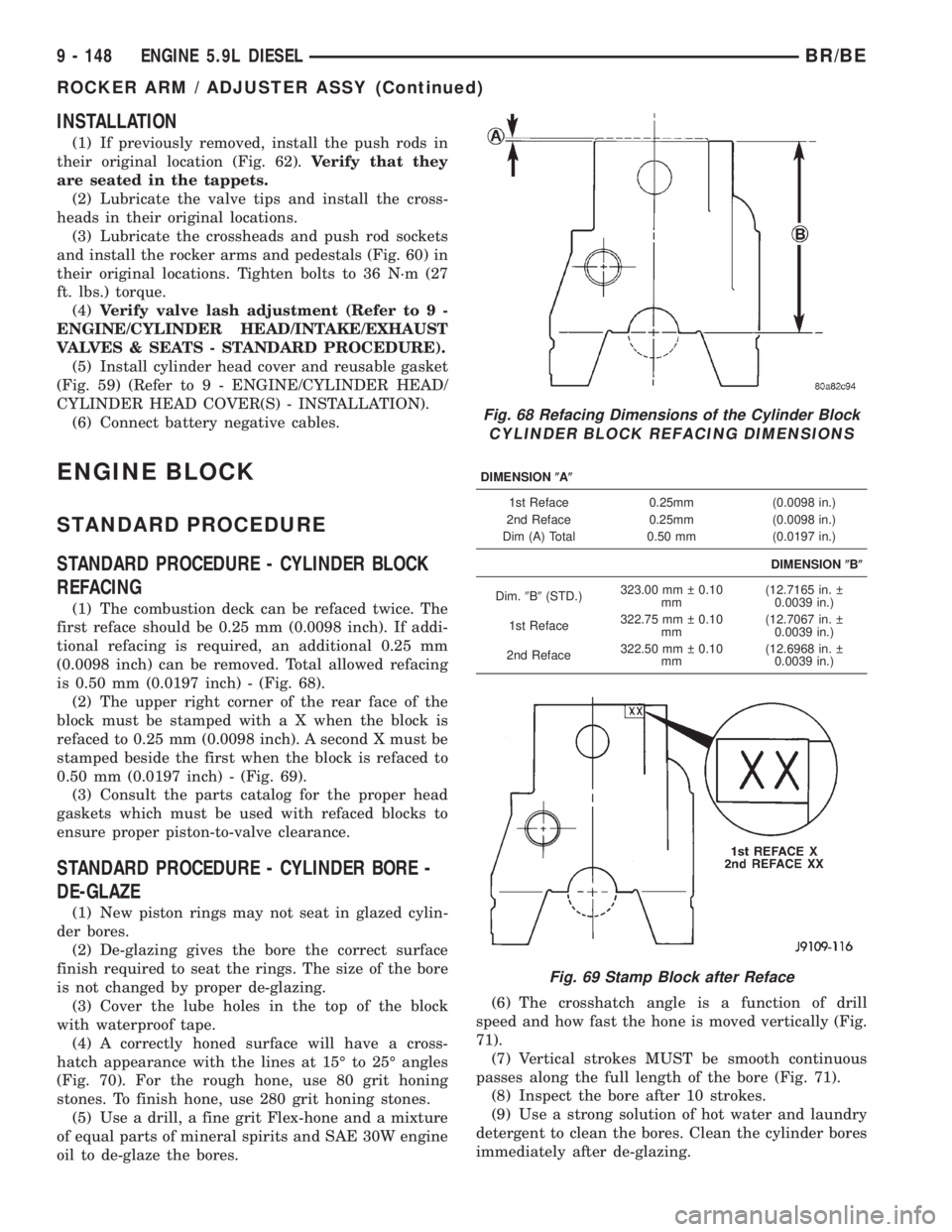
(1) The combustion deck can be refaced twice. The
first reface should be 0.25 mm (0.0098 inch). If addi-
tional refacing is required, an additional 0.25 mm
(0.0098 inch) can be removed. Total allowed refacing
is 0.50 mm (0.0197 inch) - (Fig. 68).
(2) The upper right corner of the rear face of the
block must be stamped with a X when the block is
refaced to 0.25 mm (0.0098 inch). A second X must be
stamped beside the first when the block is refaced to
0.50 mm (0.0197 inch) - (Fig. 69).
(3) Consult the parts catalog for the proper head
gaskets which must be used with refaced blocks to
ensure proper piston-to-valve clearance.
STANDARD PROCEDURE - CYLINDER BORE -
DE-GLAZE
(1) New piston rings may not seat in glazed cylin-
der bores.
(2) De-glazing gives the bore the correct surface
finish required to seat the rings. The size of the bore
is not changed by proper de-glazing.
(3) Cover the lube holes in the top of the block
with waterproof tape.
(4) A correctly honed surface will have a cross-
hatch appearance with the lines at 15É to 25É angles
(Fig. 70). For the rough hone, use 80 grit honing
stones. To finish hone, use 280 grit honing stones.
(5) Use a drill, a fine grit Flex-hone and a mixture
of equal parts of mineral spirits and SAE 30W engine
oil to de-glaze the bores.(6) The crosshatch angle is a function of drill
speed and how fast the hone is moved vertically (Fig.
71).
(7) Vertical strokes MUST be smooth continuous
passes along the full length of the bore (Fig. 71).
(8) Inspect the bore after 10 strokes.
(9) Use a strong solution of hot water and laundry
detergent to clean the bores. Clean the cylinder bores
immediately after de-glazing.
Fig. 68 Refacing Dimensions of the Cylinder Block
CYLINDER BLOCK REFACING DIMENSIONS
DIMENSION(A(
1st Reface 0.25mm (0.0098 in.)
2nd Reface 0.25mm (0.0098 in.)
Dim (A) Total 0.50 mm (0.0197 in.)
DIMENSION(B(
Dim.9B9(STD.)323.00 mm 0.10
mm(12.7165 in.
0.0039 in.)
1st Reface322.75 mm 0.10
mm(12.7067 in.
0.0039 in.)
2nd Reface322.50 mm 0.10
mm(12.6968 in.
0.0039 in.)
Fig. 69 Stamp Block after Reface
9 - 148 ENGINE 5.9L DIESELBR/BE
ROCKER ARM / ADJUSTER ASSY (Continued)
Page 1232 of 2255
Thrust Plate
Inspect the camshaft thrust plate for excessive
wear in the camshaft contact area. Measure thrust
plate thickness using the CAMSHAFT THRUST
PLATE THICKNESS CHART . Replace any thrust
plate that falls outside of these specifications:
CAMSHAFT THRUST PLATE THICKNESS CHART
9.34 mm (0.368 in.) MIN.
9.58 mm (0.377 in.) MAX.
INSTALLATION
INSTALLATIONÐCAMSHAFT BEARINGS
(1) Apply a coating of Loctitet640 Adhesive to the
backside of the new bushing. Avoid getting adhesive
in the oil hole.
(2) Use a universal cam bushing installation tool
and install the bushing so that it is even with the
front face of the cylinder block. The oil hole must be
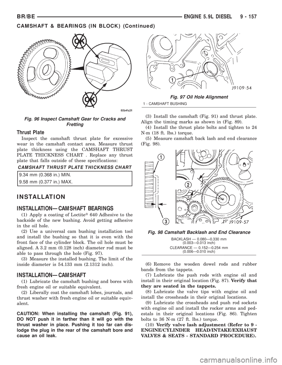
aligned. A 3.2 mm (0.128 inch) diameter rod must be
able to pass through the hole (Fig. 97).
(3) Measure the installed bushing. The limit of the
inside diameter is 54.133 mm (2.1312 inch).
INSTALLATIONÐCAMSHAFT
(1) Lubricate the camshaft bushing and bores with
fresh engine oil or suitable equivalent.
(2) Liberally coat the camshaft lobes, journals, and
thrust washer with fresh engine oil or suitable equiv-
alent.
CAUTION: When installing the camshaft (Fig. 91),
DO NOT push it in farther than it will go with the
thrust washer in place. Pushing it too far can dis-
lodge the plug in the rear of the camshaft bore and
cause an oil leak.(3) Install the camshaft (Fig. 91) and thrust plate.
Align the timing marks as shown in (Fig. 89).
(4) Install the thrust plate bolts and tighten to 24
N´m (18 ft. lbs.) torque.
(5) Measure camshaft back lash and end clearance
(Fig. 98).
(6) Remove the wooden dowel rods and rubber
bands from the tappets.
(7) Lubricate the push rods with engine oil and
install in their original location (Fig. 87).Verify that
they are seated in the tappets.
(8) Lubricate the valve tips with engine oil and
install the crossheads in their original locations.
(9) Lubricate the crossheads and push rod sockets
with engine oil and install the rocker arms and ped-
estals in their original locations (Fig. 86). Tighten
bolts to 36 N´m (27 ft. lbs.) torque.
(10)Verify valve lash adjustment (Refer to 9 -
ENGINE/CYLINDER HEAD/INTAKE/EXHAUST
VALVES & SEATS - STANDARD PROCEDURE).
Fig. 96 Inspect Camshaft Gear for Cracks and
Fretting
Fig. 97 Oil Hole Alignment
1 - CAMSHAFT BUSHING
Fig. 98 Camshaft Backlash and End Clearance
BACKLASH Ð 0.080Ð0.330 mm
(0.003Ð0.013 inch)
CLEARANCE Ð 0.152Ð0.254 mm
(0.006Ð0.010 inch)
BR/BEENGINE 5.9L DIESEL 9 - 157
CAMSHAFT & BEARINGS (IN BLOCK) (Continued)
Page 1233 of 2255
(11) Install the cylinder head cover and reusable
gasket (Fig. 85) (Refer to 9 - ENGINE/CYLINDER
HEAD/CYLINDER HEAD COVER(S) - INSTALLA-
TION).
(12) Install gear housing cover (Refer to 9 -
ENGINE/VALVE TIMING/GEAR HOUSING COVER
- INSTALLATION).
(13) Install the crankshaft damper (Fig. 83) (Refer
to 9 - ENGINE/ENGINE BLOCK/VIBRATION
DAMPER - INSTALLATION).
(14) Install the fan support/hub assembly (Fig. 82)
and tighten bolts to 24 N´m (18 ft. lbs.) torque.
(15) Install the crankcase breather housing (Refer
to 9 - ENGINE - INSTALLATION).
(16) Install the charge air cooler (with a/c con-
denser and auxiliary transmission oil cooler, if
equipped) and tighten the mounting bolts to 2 N´m
(17 in. lbs.) torque.
(17) Connect charge air cooler inlet and outlet
pipes. Tighten clamps to 10 N´m (100 in. lbs.) torque.
(18) Install the radiator upper support panel.
(19) Close radiator petcock and lower the radiator
into the engine compartment. Tighten the mounting
bolts to 11 N´m (95 in. lbs.) torque.
(20) Raise vehicle on hoist.
(21) Connect radiator lower hose and install
clamp.
(22) Connect transmission auxiliary oil cooler lines
(if equipped).
(23) Lower vehicle.
(24) Install the fan shroud and tighten the mount-
ing screws to 6 N´m (50 in. lbs.) torque.
(25) Install the viscous fan/drive assembly (Refer
to 7 - COOLING/ENGINE/RADIATOR FAN -
INSTALLATION).
(26) Install the coolant recovery and windshield
washer fluid reservoirs to the fan shroud.
(27) Connect the coolant recovery hose to the radi-
ator filler neck.
(28) Install the accessory drive belt (Refer to 7 -
COOLING/ACCESSORY DRIVE/DRIVE BELTS -
INSTALLATION).
(29) Install the front bumper assembly (Refer to 13
- FRAMES & BUMPERS/BUMPERS/FRONT
BUMPER - INSTALLATION).
(30) Add engine coolant (Refer to 7 - COOLING -
STANDARD PROCEDURE).
(31) Charge A/C system with refrigerant (if A/C
equipped) (Refer to 24 - HEATING & AIR CONDI-
TIONING/PLUMBING - STANDARD PROCEDURE).
(32) Connect the battery negative cables.
(33) Start engine and check for engine oil and cool-
ant leaks.CONNECTING ROD BEARINGS
STANDARD PROCEDUREÐCONNECTING ROD
BEARING AND CRANKSHAFT JOURNAL
CLEARANCE
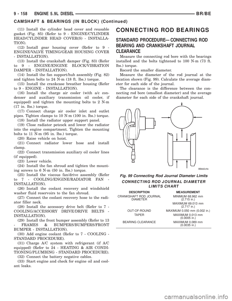
Measure the connecting rod bore with the bearings
installed and the bolts tightened to 100 N´m (73 ft.
lbs.) torque.
Record the smaller diameter.
Measure the diameter of the rod journal at the
location shown (Fig. 99). Calculate the average diam-
eter for each side of the journal.
The clearance is the difference between the con-
necting rod bore (smallest diameter) and the average
diameter for each side of the crankshaft journal.
Fig. 99 Connecting Rod Journal Diameter Limits
CONNECTING ROD JOURNAL DIAMETER
LIMITS CHART
DESCRIPTION MEASUREMENT
CRANKSHAFT ROD JOURNAL
DIAMETERMINIMUM 68.962 mm
(2.715 in.)
MAXIMUM 69.013 mm
(2.717 in.)
OUT-OF-ROUND MAXIMUM 0.050 mm (0.002 in.)
TAPER MAXIMUM 0.013 mm
(0.0005 in.)
BEARING CLEARANCE MAXIMUM 0.089 mm
(0.0035 in.)
9 - 158 ENGINE 5.9L DIESELBR/BE
CAMSHAFT & BEARINGS (IN BLOCK) (Continued)
Page 1234 of 2255
CONNECTING ROD JOURNAL DIAMETER
LIMITS CHART
DESCRIPTION MEASUREMENT
CRANKSHAFT ROD
JOURNAL DIAMETERMINIMUM 68.962 mm
(2.715 in.)
MAXIMUM 69.013 mm
(2.717 in.)
OUT-OF-ROUND MAXIMUM 0.050 mm
(0.002 in.)
TAPER MAXIMUM 0.013 mm
(0.0005 in.)
BEARING CLEARANCE MAXIMUM 0.089 mm
(0.0035 in.)
If the crankshaft is within limits, replace the bear-
ing. If the crankshaft is out of limits, grind the
crankshaft to the next smaller size and use oversize
rod bearings.
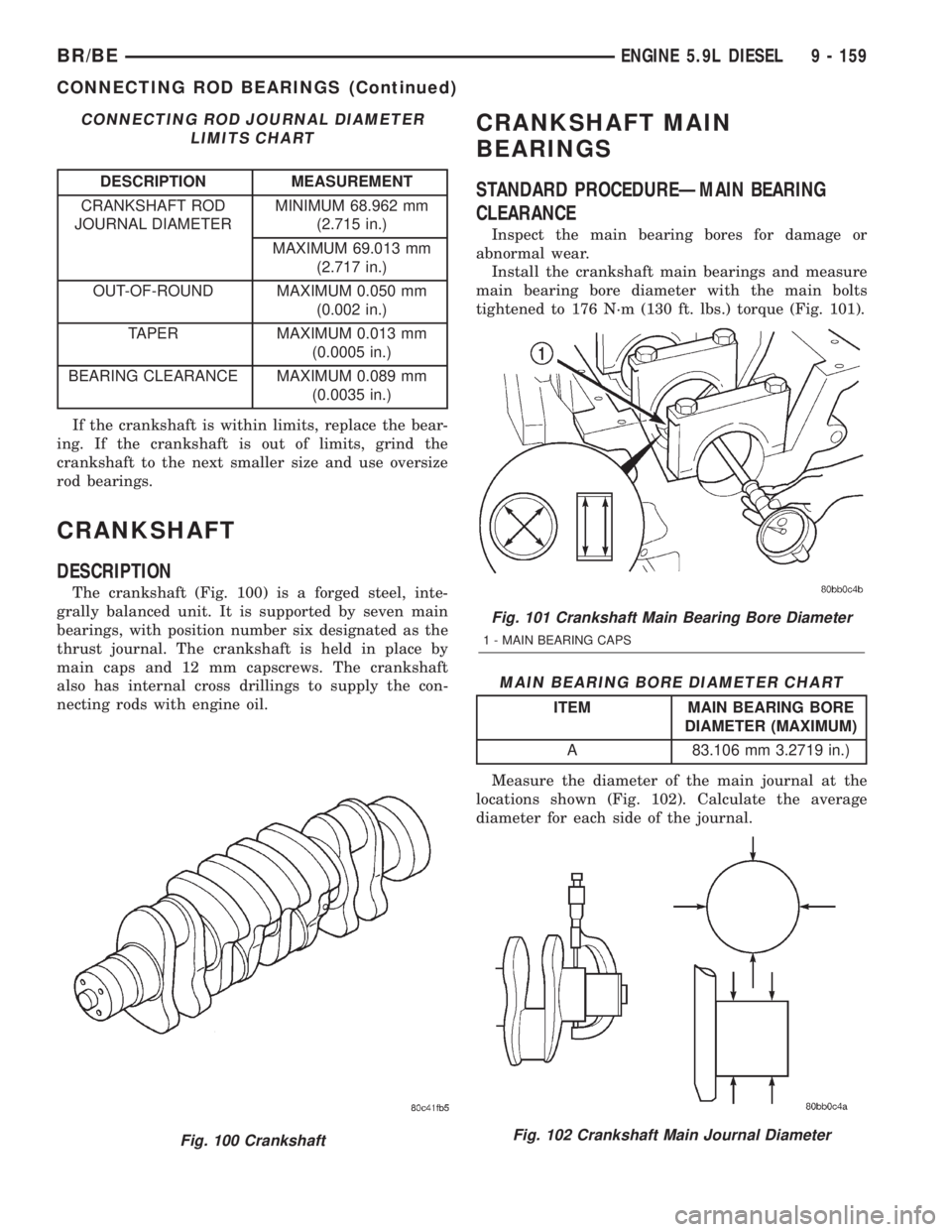
CRANKSHAFT
DESCRIPTION
The crankshaft (Fig. 100) is a forged steel, inte-
grally balanced unit. It is supported by seven main
bearings, with position number six designated as the
thrust journal. The crankshaft is held in place by
main caps and 12 mm capscrews. The crankshaft
also has internal cross drillings to supply the con-
necting rods with engine oil.
CRANKSHAFT MAIN
BEARINGS
STANDARD PROCEDUREÐMAIN BEARING
CLEARANCE
Inspect the main bearing bores for damage or
abnormal wear.
Install the crankshaft main bearings and measure
main bearing bore diameter with the main bolts
tightened to 176 N´m (130 ft. lbs.) torque (Fig. 101).
MAIN BEARING BORE DIAMETER CHART
ITEM MAIN BEARING BORE
DIAMETER (MAXIMUM)
A 83.106 mm 3.2719 in.)
Measure the diameter of the main journal at the
locations shown (Fig. 102). Calculate the average
diameter for each side of the journal.
Fig. 100 Crankshaft
Fig. 101 Crankshaft Main Bearing Bore Diameter
1 - MAIN BEARING CAPS
Fig. 102 Crankshaft Main Journal Diameter
BR/BEENGINE 5.9L DIESEL 9 - 159
CONNECTING ROD BEARINGS (Continued)